EP0686713B1 - Presser Finger - Google Patents
Presser Finger Download PDFInfo
- Publication number
- EP0686713B1 EP0686713B1 EP19940108955 EP94108955A EP0686713B1 EP 0686713 B1 EP0686713 B1 EP 0686713B1 EP 19940108955 EP19940108955 EP 19940108955 EP 94108955 A EP94108955 A EP 94108955A EP 0686713 B1 EP0686713 B1 EP 0686713B1
- Authority
- EP
- European Patent Office
- Prior art keywords
- opening
- roving
- guide groove
- presser
- blade
- Prior art date
- Legal status (The legal status is an assumption and is not a legal conclusion. Google has not performed a legal analysis and makes no representation as to the accuracy of the status listed.)
- Expired - Lifetime
Links
- 230000007704 transition Effects 0.000 claims description 10
- 238000009987 spinning Methods 0.000 claims description 2
- 239000000835 fiber Substances 0.000 description 8
- 206010020112 Hirsutism Diseases 0.000 description 3
- 238000010422 painting Methods 0.000 description 3
- 238000007493 shaping process Methods 0.000 description 3
- 238000004804 winding Methods 0.000 description 3
- 230000007423 decrease Effects 0.000 description 2
- 238000009825 accumulation Methods 0.000 description 1
- 230000015572 biosynthetic process Effects 0.000 description 1
- 238000007596 consolidation process Methods 0.000 description 1
- 238000004519 manufacturing process Methods 0.000 description 1
- 238000000034 method Methods 0.000 description 1
- 238000003825 pressing Methods 0.000 description 1
- 230000002265 prevention Effects 0.000 description 1
- 238000007788 roughening Methods 0.000 description 1
Images
Classifications
-
- D—TEXTILES; PAPER
- D01—NATURAL OR MAN-MADE THREADS OR FIBRES; SPINNING
- D01H—SPINNING OR TWISTING
- D01H7/00—Spinning or twisting arrangements
- D01H7/02—Spinning or twisting arrangements for imparting permanent twist
- D01H7/24—Flyer or like arrangements
- D01H7/26—Flyer constructions
- D01H7/30—Flyer constructions with guide channels formed in legs, e.g. slubbing flyers
- D01H7/32—Flyer constructions with guide channels formed in legs, e.g. slubbing flyers with pressing devices
Definitions
- the invention relates to a press finger for one Flyer wing for guiding a fuse to one Coil surface.
- the roving on the flyer is known to be done by a Flyer wing with integrated sliver guide tube and by rotating the wing with a real one Provide rotation for consolidation.
- the roving is opened at the exit of the sliver guide tube passed the press finger and led to the press finger sheet.
- the press finger is usually designed so that a contact pressure is generated to a high spool weight to reach.
- the press finger blade with a guide groove and a round feed-through for the roving.
- the guide groove described here is a in Thread running direction tapered, V-shaped groove, the lateral boundaries are tangents that are in the open into a circular opening.
- This design is intended to shape the fuse Braking of the thread course and painting of protruding ones Serve fibers on the spool.
- the disadvantage here is that the Fused by getting a twist and the weird one Course of the guide groove wall from the guide groove strives out and not while laying down on the spool inevitably remains in the groove. This has negative ones Effects on the formation of the fuse when laying down the bobbin causes a decrease in thread quality and leads to more frequent ruptures.
- the object of the invention is therefore that Optimizing the sliver barrel so that an optimal shaping of the Fuse and binding of edge fibers before the Filing takes place on the coil and minimizing the Hairiness is achieved.
- the pear-shaped opening in the press finger sheet is one Transverse opening, from two sides through a curvature is limited, with one being a larger one Curvature diameter and the other a smaller one Has curvature diameter.
- This is above and below Opening delimited by two divergent straight lines, each merge tangentially into the arcs. The smaller the both diameters point in the direction of the match.
- the center of this opening is preferably in one Distance either above or below the center line and in the longitudinal direction in about the first third of the Press finger blade be arranged in the direction of the roving.
- the match guide groove is preferably exactly in the middle of the Press finger blade introduced. This starts with one Depth that is approximately half the thickness of the press finger corresponds, from the opening and ending, in The direction of the roving steadily becomes flatter, shortly before the Press finger edge. The flanks of this fuse guide groove only converge slightly in the direction of the match, so that they don’t touch until they run out.
- the tapering in the direction of the match The opening is slightly off-center, opens out in this case the upper flank tangentially into the larger one Curvature and the opposite flank in the area the smaller curvature.
- the fuse slides additionally supported by the tapering of the opening in Match direction and the arrangement described at the beginning the groove flanks to the opening, on the upper larger one Curvature and the adjoining groove flank. Thereby, and that the upper flank of the groove is only slight The fuse is forced into the groove and pressed against the upper flank.
- This optimal Match run causes an optimal shaping of the match and at the same time incorporating the edge fibers before Put it on the spool.
- the hairiness of the fuse is significantly minimized and thus leads to the securing of a high Final yarn quality and the manufacture flawless Drainage conditions of the roving in the following Spinning passage.
- the sliver guide groove is an accumulation of fibers and an This transition is to prevent the fuse from roughening a slope that goes from the bottom edge of the opening to the opening and deepest part of the match groove leads. It is also possible to change the slope to the bottom of the match groove with an additional Radius. However, the transition can be done exactly as Transition radius to be formed.
- the variant with the The groove guide groove in the middle should be preferred.
- the pressure finger sheet lies with pressure the coil.
- the fuse in the fuse guide groove the areas above and below this Use the task to thread the wound thread on the spool smooth out.
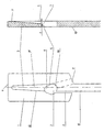
- the figure shows the design of a Press fingers for a right-handed fuse.
- the press finger of a flyer wing is known to exist from a press finger arm 10, which is only hinted at here is shown, and a press finger sheet 1.
- Das Press finger sheet 1 has an approximately rectangular shape, wherein however on the side on which the press finger arm 10 is attached, from the press finger arm 10 each Is worked obliquely.
- the thickness of one Press finger sheet 1 is about 3-5 mm.
- This opening 2 is of two Pages limited by a curvature 4, 14, the one a larger radius of curvature and the other has a smaller radius of curvature. Above and below is this opening 2 of two diverging straight lines limited, the tangential into the curvatures 4, 14th pass over. The smaller of the two curvatures 4 points in Match direction. The center of this opening 2 is at a distance slightly below the center line 15 and in Longitudinal direction about a third of the length of the Press finger sheet 1 arranged from the feed direction.
- a sliver guide groove is worked into this opening 2 3.
- This groove 3 extends in the middle of the Pressing finger blade 1 in the longitudinal direction, directly on the Opening 2 begins until a few mm before that Pressfinger blade end 6.
- the upper groove flank 5 lies tangent to the large radius of curvature and the lower one Groove edge 12 opens in the area of the smaller radius of curvature on.
- the flanks 5, 12 of the sliver guide groove 3 run from the opening 2 at the same angle in Match direction towards each other. This angle is however chosen so small that the flanks 5, 12 up to do not touch their leakage and a distance from each other.
- the depth t of the sliver guide groove 3 is at its lowest point, namely at the confluence with the opening 2 about half the thickness of the press finger sheet thickness. you The course in the direction of the roving is steadily flattening, so that they shortly before the press leaf edge 6 in the Pressfinger leaf upper edge 11 passes, the outlet is formed by a radius.
- the transition from the lower edge 13 of the press finger Opening 2 in the sliver guide groove 3 is a slope 7. Through this bevel 7 is a while the thread is running Prevention of fibers.
- the slope 7 is like this chosen that the fuse should wear through the opening 2 can slide into the sliver guide groove 3.
- the fuse is turned by rotating the flyer wing turned to the right and is due to the preserved Dralls strives to hike up.
- the oblique design of the transition 7 and the tangential to the large curvature 14 at a small angle the upper groove flank 5 lies the fuse of the winding process on the groove flank 5.
- the concern the fuse on this flank already supports before Winding up an optimal shaping of the fuse, edge fibers are integrated into the fuse and the hairiness of the Fuse is reduced significantly.
Landscapes
- Engineering & Computer Science (AREA)
- Mechanical Engineering (AREA)
- Textile Engineering (AREA)
- Spinning Or Twisting Of Yarns (AREA)
Description
Claims (7)
- Preßfinger für Flyerflügel an Spinnereimaschinen, bestehend aus einem Preßfingerarm (10) und einem Preßfingerblatt (1), wobei das Preßfingerblatt (1) eine Öffnung (2) und eine Luntenführungsnut (3) aufweist, wobei die Öffnung (2) zur Luntenführung unrund ist und sich in Luntenlaufrichtung verjüngt,
dadurch gekennzeichnet, daßdie Öffnung (2) im Preßfingerblatt (1) etwa birnenförmig ist,die schmalere Seite (4) der Öffnung (2) in Luntenlaufrichtung weist,die Luntenführungsnut (3) des Preßfingerblattes (1) in Luntenlaufrichtung hinter der Öffnung (2) von der Öffnung (2) bis vor das Preßfingerblattende (6) verläuft undder Übergang von der Öffnung (2) in die Luntenführungsnut (3) außermittig der Öffnung (2) erfolgt. - Preßfinger nach Anspruch 1,
dadurch gekennzeichnet, daß
der Übergang von der Öffnung (2) in die Luntenführungsnut (3) derart außermittig erfolgt, daß die Lunte durch die aufgenommene Drehung gegen eine Flanke (5) der Luntenführungsnut (3) läuft. - Preßfinger nach einem der vorhergehenden Ansprüche ,
dadurch gekennzeichnet, daß
die Luntenführungsnut (3) an dem der Öffnung (2) zugewandten Ende eine Tiefe (t) aufweist, die vorzugsweise der Hälfte der Preßfingerblattdicke entspricht und daß die Luntenführungsnut (3) in Luntenlaufrichtung derart schräg nach oben verläuft, daß sie vor dem Preßfingerblattende (6) endet. - Preßfinger nach einem der vorhergehenden Ansprüche,
dadurch gekennzeichnet, daß
die beiden Flanken (5, 12) der Luntenführungsnut (3) in Luntenlaufrichtung konvergierend verlaufen. - Preßfinger nach einem der vorhergehenden Ansprüche,
dadurch gekennzeichnet, daß
eine Flanke (5) der Luntenführungsnut (3) tangential in die der Zuführrichtung der Lunte zugewandte Krümmung der Öffnung (2) einmündet und die andere Flanke im Bereich der kleinen Krümmung (4) der Öffnung (2) einmündet. - Preßfinger nach einem der vorhergehenden Ansprüche,
dadurch gekennzeichnet, daß
der Übergang von der Preßfingerblattunterkante (13) der Öffnung (2) zu dem der Öffnung (2) zugewandten Luntenführungsnutboden (3) eine in Luntenflaufrichtung verlaufende Schräge (7) ist. - Preßfinger nach einem der Ansprüche 1 bis 5,
dadurch gekennzeichnet, daß
der Übergang von der Preßfingerblattunterkante (13) der Öffnung (2) zu dem der Öffnung (2) zugewandten Luntenführungsnutboden (3) ein Radius ist.
Priority Applications (2)
| Application Number | Priority Date | Filing Date | Title |
|---|---|---|---|
| EP19940108955 EP0686713B1 (de) | 1994-06-10 | 1994-06-10 | Presser Finger |
| DE59408118T DE59408118D1 (de) | 1994-06-10 | 1994-06-10 | Presser Finger |
Applications Claiming Priority (1)
| Application Number | Priority Date | Filing Date | Title |
|---|---|---|---|
| EP19940108955 EP0686713B1 (de) | 1994-06-10 | 1994-06-10 | Presser Finger |
Publications (2)
| Publication Number | Publication Date |
|---|---|
| EP0686713A1 EP0686713A1 (de) | 1995-12-13 |
| EP0686713B1 true EP0686713B1 (de) | 1999-04-14 |
Family
ID=8216008
Family Applications (1)
| Application Number | Title | Priority Date | Filing Date |
|---|---|---|---|
| EP19940108955 Expired - Lifetime EP0686713B1 (de) | 1994-06-10 | 1994-06-10 | Presser Finger |
Country Status (2)
| Country | Link |
|---|---|
| EP (1) | EP0686713B1 (de) |
| DE (1) | DE59408118D1 (de) |
Cited By (1)
| Publication number | Priority date | Publication date | Assignee | Title |
|---|---|---|---|---|
| EP2581476A2 (de) | 2011-10-13 | 2013-04-17 | Oerlikon Textile GmbH & Co. KG | Pressfinger für eine Vorspinnmaschine |
Families Citing this family (1)
| Publication number | Priority date | Publication date | Assignee | Title |
|---|---|---|---|---|
| CN102493041B (zh) * | 2011-12-08 | 2014-11-26 | 天津宏大纺织机械有限公司 | 防脱纱锭翼压掌 |
Family Cites Families (4)
| Publication number | Priority date | Publication date | Assignee | Title |
|---|---|---|---|---|
| US1426443A (en) * | 1920-08-26 | 1922-08-22 | Whitin Machine Works | Flier |
| US2046376A (en) * | 1935-10-29 | 1936-07-07 | Philip A Gwaltney | Flyer |
| GB669376A (en) * | 1949-07-21 | 1952-04-02 | William George Reynolds | Improved presser feet for textile flyers |
| DE3023241C2 (de) * | 1980-06-21 | 1983-12-08 | C. Eugen Maier Metallverarbeitung Gmbh, 7012 Fellbach | Preßfinger für einen Flyerflügel |
-
1994
- 1994-06-10 EP EP19940108955 patent/EP0686713B1/de not_active Expired - Lifetime
- 1994-06-10 DE DE59408118T patent/DE59408118D1/de not_active Expired - Fee Related
Cited By (4)
| Publication number | Priority date | Publication date | Assignee | Title |
|---|---|---|---|---|
| EP2581476A2 (de) | 2011-10-13 | 2013-04-17 | Oerlikon Textile GmbH & Co. KG | Pressfinger für eine Vorspinnmaschine |
| DE102011115850A1 (de) | 2011-10-13 | 2013-04-18 | Oerlikon Textile Gmbh & Co. Kg | Pressfinger für eine Vorspinnmaschine |
| EP2581476A3 (de) * | 2011-10-13 | 2015-04-08 | Saurer Germany GmbH & Co. KG | Pressfinger für eine Vorspinnmaschine |
| DE102011115850B4 (de) | 2011-10-13 | 2019-01-10 | Saurer Spinning Solutions Gmbh & Co. Kg | Pressfinger für eine Vorspinnmaschine |
Also Published As
| Publication number | Publication date |
|---|---|
| DE59408118D1 (de) | 1999-05-20 |
| EP0686713A1 (de) | 1995-12-13 |
Similar Documents
| Publication | Publication Date | Title |
|---|---|---|
| EP0532964B1 (de) | Drehteller für Faserbandablageeinrichtungen | |
| DE4224632B4 (de) | Vorrichtung zum Offenend-Spinnen | |
| DE3332498A1 (de) | Verbesserung an offenendspinnmaschinen | |
| DE2810843C2 (de) | Vorrichtung zum Offenend-Spinnen | |
| DE2649778C2 (de) | Vorrichtung zum Paraffinieren von Garn | |
| DE2312169B2 (de) | Faserliefer- und Auflösevorrichtung für eine Offenendspinneinheit | |
| EP0686713B1 (de) | Presser Finger | |
| DE202007011954U1 (de) | Streckwerk und Unterwalzen-Lagerschlitten | |
| DE3013995C2 (de) | Vorrichtung zur Herstellung von Effektgarn | |
| DE19614009C2 (de) | Vorrichtung zum Vereinzeln von Haken | |
| DE19906111A1 (de) | Faden-Abzugsdüse in einer Open-End-Spinnmaschine | |
| DE3006863C2 (de) | Vorrichtung zur Herstellung von Effektgarn | |
| EP0182241B1 (de) | Vorrichtung zum Friktionsspinnen | |
| DE19733614A1 (de) | Absaugeinrichtung am Streckwerk einer Spinnmaschine | |
| DE1660210A1 (de) | Vorrichtung zur Fadentrennung fuer Falschdraht-Kraeuselmaschinen | |
| DE2919916A1 (de) | Fadenzufuehreinrichtung fuer flachstrickmaschinen | |
| EP2581476B1 (de) | Pressfinger für eine Vorspinnmaschine | |
| DE3321228A1 (de) | Vorrichtung zum oe-friktionsspinnen | |
| DE3715811A1 (de) | Luntenfuehrungs-vorrichtung | |
| DE202007012066U1 (de) | Coregarn-Einrichtung und Spulenseparator | |
| DE3730064C1 (en) | Thread-deflecting roller for textile machines, especially twisting machines | |
| EP4474556A1 (de) | Fadenliefergerät | |
| DE9305070U1 (de) | Maschine zur Herstellung eines Rohrstutzens | |
| DE3741064C2 (de) | ||
| DE1685983C (de) | Fadenführer für die Erzeugung von Mouline-Zwirnen auf Ballonlos-Ringzwirnmaschinen |
Legal Events
| Date | Code | Title | Description |
|---|---|---|---|
| PUAI | Public reference made under article 153(3) epc to a published international application that has entered the european phase |
Free format text: ORIGINAL CODE: 0009012 |
|
| AK | Designated contracting states |
Kind code of ref document: A1 Designated state(s): CH DE ES IT LI |
|
| 17P | Request for examination filed |
Effective date: 19960612 |
|
| 17Q | First examination report despatched |
Effective date: 19971024 |
|
| GRAG | Despatch of communication of intention to grant |
Free format text: ORIGINAL CODE: EPIDOS AGRA |
|
| GRAG | Despatch of communication of intention to grant |
Free format text: ORIGINAL CODE: EPIDOS AGRA |
|
| GRAH | Despatch of communication of intention to grant a patent |
Free format text: ORIGINAL CODE: EPIDOS IGRA |
|
| GRAH | Despatch of communication of intention to grant a patent |
Free format text: ORIGINAL CODE: EPIDOS IGRA |
|
| GRAA | (expected) grant |
Free format text: ORIGINAL CODE: 0009210 |
|
| AK | Designated contracting states |
Kind code of ref document: B1 Designated state(s): CH DE ES IT LI |
|
| PG25 | Lapsed in a contracting state [announced via postgrant information from national office to epo] |
Ref country code: ES Free format text: THE PATENT HAS BEEN ANNULLED BY A DECISION OF A NATIONAL AUTHORITY Effective date: 19990414 |
|
| REG | Reference to a national code |
Ref country code: CH Ref legal event code: EP |
|
| REF | Corresponds to: |
Ref document number: 59408118 Country of ref document: DE Date of ref document: 19990520 |
|
| REG | Reference to a national code |
Ref country code: CH Ref legal event code: NV Representative=s name: MARIANNE SZILAGYI |
|
| PLBE | No opposition filed within time limit |
Free format text: ORIGINAL CODE: 0009261 |
|
| STAA | Information on the status of an ep patent application or granted ep patent |
Free format text: STATUS: NO OPPOSITION FILED WITHIN TIME LIMIT |
|
| 26N | No opposition filed | ||
| PGFP | Annual fee paid to national office [announced via postgrant information from national office to epo] |
Ref country code: CH Payment date: 20030625 Year of fee payment: 10 |
|
| PGFP | Annual fee paid to national office [announced via postgrant information from national office to epo] |
Ref country code: DE Payment date: 20030829 Year of fee payment: 10 |
|
| PG25 | Lapsed in a contracting state [announced via postgrant information from national office to epo] |
Ref country code: LI Free format text: LAPSE BECAUSE OF NON-PAYMENT OF DUE FEES Effective date: 20040630 Ref country code: CH Free format text: LAPSE BECAUSE OF NON-PAYMENT OF DUE FEES Effective date: 20040630 |
|
| PG25 | Lapsed in a contracting state [announced via postgrant information from national office to epo] |
Ref country code: DE Free format text: LAPSE BECAUSE OF NON-PAYMENT OF DUE FEES Effective date: 20050101 |
|
| REG | Reference to a national code |
Ref country code: CH Ref legal event code: PL |
|
| PG25 | Lapsed in a contracting state [announced via postgrant information from national office to epo] |
Ref country code: IT Free format text: LAPSE BECAUSE OF NON-PAYMENT OF DUE FEES;WARNING: LAPSES OF ITALIAN PATENTS WITH EFFECTIVE DATE BEFORE 2007 MAY HAVE OCCURRED AT ANY TIME BEFORE 2007. THE CORRECT EFFECTIVE DATE MAY BE DIFFERENT FROM THE ONE RECORDED. Effective date: 20050610 |