EP0687424A1 - Device for rolling elongated elements, particularly for producing tobacco items - Google Patents
Device for rolling elongated elements, particularly for producing tobacco items Download PDFInfo
- Publication number
- EP0687424A1 EP0687424A1 EP95108669A EP95108669A EP0687424A1 EP 0687424 A1 EP0687424 A1 EP 0687424A1 EP 95108669 A EP95108669 A EP 95108669A EP 95108669 A EP95108669 A EP 95108669A EP 0687424 A1 EP0687424 A1 EP 0687424A1
- Authority
- EP
- European Patent Office
- Prior art keywords
- speed
- axis
- rolling
- brake element
- rocker arm
- Prior art date
- Legal status (The legal status is an assumption and is not a legal conclusion. Google has not performed a legal analysis and makes no representation as to the accuracy of the status listed.)
- Granted
Links
Images



Classifications
-
- A—HUMAN NECESSITIES
- A24—TOBACCO; CIGARS; CIGARETTES; SIMULATED SMOKING DEVICES; SMOKERS' REQUISITES
- A24C—MACHINES FOR MAKING CIGARS OR CIGARETTES
- A24C5/00—Making cigarettes; Making tipping materials for, or attaching filters or mouthpieces to, cigars or cigarettes
- A24C5/47—Attaching filters or mouthpieces to cigars or cigarettes, e.g. inserting filters into cigarettes or their mouthpieces
- A24C5/471—Attaching filters or mouthpieces to cigars or cigarettes, e.g. inserting filters into cigarettes or their mouthpieces by means of a connecting band
Definitions
- the present invention relates to a device for rolling elongated elements, particularly for producing tobacco items.
- the present invention is particularly advantageous for producing filter-tipped cigarettes, to which the following description refers purely by way of example.
- filter-tipped cigarettes are rolled as part of laser perforating processes for producing ventilated cigarettes; or groups, each comprising two coaxial cigarette portions separated by a double filter, are rolled for connecting the cigarette portions to the double filter by means of an adhesive strip which is rolled about the filter and the adjacent ends of the cigarette portions.
- Known rolling devices for producing double filter-tipped cigarettes comprise a conveyor roller with a number of seats equally spaced about the outer surface of the roller and for receiving and retaining respective groups; and, normally, also a fixed plate facing an outer peripheral portion of the roller and defining with it a rolling channel of a width approximately equal to but no larger than the diameter of the cigarette portions and the double filter.
- the conveyor roller is rotated about its axis at constant speed to feed the groups and respective adhesive strips - connected in projecting manner to the groups - to the inlet of the channel at a first given speed, and to feed the groups along the channel at a second speed equal to half the first speed.
- the rolling channel inlet is normally provided with a rolling initiating device normally defined by a fixed tooth which, as described and illustrated, for example, in US Patent n. 3,527,234, extends partly inside the channel and, as the groups arrive, cooperates with them by friction to withdraw them from the respective seats on the conveyor roller and rotate them backwards about their respective axes.
- a rolling initiating device normally defined by a fixed tooth which, as described and illustrated, for example, in US Patent n. 3,527,234, extends partly inside the channel and, as the groups arrive, cooperates with them by friction to withdraw them from the respective seats on the conveyor roller and rotate them backwards about their respective axes.
- each group encounters the initiating tooth at full speed, and is subjected to extremely sharp (theoretically infinite) deceleration which, regardless of impact speed, can only be absorbed by elastic deformation of the group itself. Since, for output speeds over and above a given limit, impact is such as to result in irreparable damage to the group, the above fixed initiating tooth design obviously limits the output capacity of the filter assembly machine.
- US Patent n. 4,825,882 relates to a rolling device wherein the fixed initiating tooth described above is replaced by a succession of initiating teeth fitted to a roller and moving with it at a speed equal to half the traveling speed of the groups.
- a rolling device for elongated elements for producing tobacco items
- the device comprising powered conveyor means presenting a transportation surface with a number of seats for receiving respective elongated elements; a plate facing a portion of the transportation surface, and presenting a rolling bed defining a rolling channel with said transportation surface; and rolling initiating means located at the inlet of said rolling channel; characterized in that said initiating means comprise braking means for successively engaging and gradually reducing the speed of said elongated elements from a first speed at which said conveyor means travel, to a second speed at which the elongated elements travel along said channel.
- Number 1 in Figure 1 indicates a rolling device forming part of a filter assembly machine 1a, and for connecting, by means of respective gummed strips 2, the two cigarette portions (not shown) and the intermediate double filter (not shown) of a number of groups 3 fed successively to device 1 by a known feed roller (not shown).
- Device 1 comprises a roller 4 rotated clockwise (in Figure 1) about its axis 5 by known drive means (not shown), and at a constant surface speed V1 in relation to a frame 6 parallel to the Figure 1 and 2 planes; and a roller 7 mounted for rotation on frame 6, and rotating anticlockwise (in Figure 1) at substantially the same surface speed as roller 4, and about an axis 8 parallel to axis 5.
- Roller 7 is tangent to roller 4 at a transfer station 9 where groups 3 are transferred from respective suction seats 10 equally spaced about the peripheral surface 11 of roller 4, to respective suction seats 10a equally spaced about the peripheral surface of roller 7.
- each strip 2 A front portion (in the traveling direction of roller 4) of each strip 2 is located between respective group 3 and respective seat 10, and a rear portion of each strip 2 extends rearwards of respective group 3 and is maintained contacting the peripheral surface 11 of roller 4 by known suction means (not shown).
- Device 1 also comprises a fixed plate 12 facing a portion of surface 11 and defined, on the side facing surface 11, by a curved notched surface parallel to surface 11 and forming a rolling bed 13. Together with surface 11, rolling bed 13 defines a rolling channel 14, the width of which is approximately equal to but no larger than the diameter of groups 3, and is larger than the diameter of groups 3 if added to the depth of seat 10, so that a group 3 housed inside seat 10 could theoretically travel along the whole of channel 14 without coming into contact with rolling bed 13.
- Device 1 also comprises a rolling initiating unit 15 adjacent to inlet 16 of channel 14, and which provides, with substantially no impact, for gradually braking each group 3 upstream from inlet 16, easing it out of respective seat 10, and rolling it backwards about respective axis 3a and along surface 11, so as to partly wind gummed strip 2 about the double filter (not shown) and the ends of the two cigarette portions (not shown).
- a rolling initiating unit 15 adjacent to inlet 16 of channel 14, and which provides, with substantially no impact, for gradually braking each group 3 upstream from inlet 16, easing it out of respective seat 10, and rolling it backwards about respective axis 3a and along surface 11, so as to partly wind gummed strip 2 about the double filter (not shown) and the ends of the two cigarette portions (not shown).
- Device 15 comprises a drum type cam 17 presenting an inner sleeve 18 fitted, by means of a key 19, to a shaft 20 supported in angularly fixed manner on frame 6 and presenting an axis 21 parallel to axes 5 and 8.
- Cam 17 presents a profile 22 for a number of tappet rollers 23, each of which is maintained contacting profile 22 by a known guide device (not shown), and is mounted for rotation, by means of a respective pin 24 parallel to axis 21, on one end of a respective rocker arm 25 pivoting, by means of a respective pin 26 parallel to pins 24, on a drum 27 coaxial with axis 21.
- Drum 27 is fitted in known manner (not shown) to a drive shaft (not shown) in turn fitted through frame 6 and by which drum 27 is rotated anticlockwise (in Figure 1) about axis 21 at an angular speed equal to that of roller 4, and at a surface speed V2 lower than speed V1.
- Each rocker arm 25 comprises a first arm 28, a first end of which supports tappet roller 23, and the second end of which is fitted through with an end portion 29 of pin 26; and a second arm 30 extending radially outwards from the free end of portion 29, and forming an angle of less than 180° with arm 28.
- Arm 30 comprises a tooth, the free end of which is defined by a surface 31 parallel to pin 26 and sloping towards axis 21 from the tip 32 of the front lateral edge of arm 30 with reference to the rotation direction of drum 27.
- Profile 22 of cam 17 comprises a substantially spiral-shaped portion 33 extending over a roughly 330° arc AB - measured anticlockwise, i.e. in the rotation direction of drum 27 - about axis 21 and from a point A with a maximum radius "R", to a point B with a minimum radius "r”; and a concave portion 34 extending over a roughly 30° arc BA - measured in the rotation direction of drum 27 - and facing and substantially parallel to peripheral surface 11 of roller 4.
- Each rocker arm 25 therefore rotates about axis 21 together with drum 27, while at the same time oscillating about the rotation axis of 26 in relation to drum 27, so that, for each turn of drum 27, each tip 32 describes a closed path 35 at a surface speed V3 equal to the sum of two parts: a first part which is constant and substantially equal to the surface speed V2 of drum 27 about axis 21; and a second part V4 which is variable and depends on the rotation of rocker arm 25 about the axis of pin 26.
- speeds V4 and V2 are in the same direction as roller 23 rolls along portion 33, and are in opposite directions as roller 23 rolls along portion 34; and portions 33 and 34 are so formed that, when roller 23 is tangent to profile 22 at point B, speed V3 reaches a substantially maximum value equal to V1, and, as roller 23 rolls along a given portion of portion 34, speed V4 assumes the same but opposite value to speed V2 so that speed V3 is zero.
- each rocker arm 25 is indicated by a complex number consisting of number 25 and two letters, the first (A-G) indicating the view referred to, and the second (L-R) indicating the position (to the left or right) of the rocker arm 25 referred to in each view.
- rocker arm 25AR - is located at a point along path 35 upstream from two points C and D at which path 35 intersects the extension of the curved surface defining rolling bed 13.
- roller 23 of rocker arm 25AR rolls, without sliding, along the end portion of portion 33 of cam profile 22 preceding point B at which cam 17 presents a minimum radius "r"; and speed V4 of tip 32 of rocker arm 25AR is in the same direction as speed V2, so that speed V3 is greater than V2 but still less than V1, and rocker arm 25AR rotates anticlockwise (in Figure 2) about the axis of pin 26.
- the respective group 3 - only visible as of Figure 2d - travels in time with tip 32 towards point C at speed V1 and at an angular speed of zero in relation to its axis 3a.
- rocker arm 25 in question reaches the position of rocker arm 25AL, the roller 23 of which is tangent to cam profile 22 substantially at point B of minimum radius "r", and the tip 32 of which is located between points C and D and travels at a speed V3 which has risen to a maximum value substantially equal to V1.
- rocker arm 25 reaching the position of rocker arm 25AL it is joined by respective group 3 which contacts surface 31 at a speed tending asymptotically towards zero.
- the negative speed V4 of tip 32 equals, in absolute value, speed V2, so that tip 32 is positioned stationary in front of inlet 16 of rolling channel 14, and group 3, by now eased entirely out of respective seat 10, reaches its full rolling speed VR, rolls over tip 32 and deforms radially to roll over rocker arm 25 when this reaches the position of 25EL, and rolls with substantially no impact into rolling channel 14.
- group 3 contacts, along diametrically opposite lines, fixed tip 32 on the one side, and surface 11 traveling at speed V1 on the other, so that axis 3a of group 3 travels, as shown in Figure 3, at a speed equal to half speed V1. More specifically, due to elastic hysteresis, group 3 reaches its full rolling speed VR an instant before axis 3a reaches speed V1/2 at which axis 3a then proceeds along the whole of channel 14.
- rolling device 1 therefore provides, with no impact, for gradually slowing down each group 3 before it enters channel 14, and so minimizing the stress to which group 3 is subjected.
- Figure 4 shows a variation wherein arm 30 is replaced by an arm 37 comprising a substantially L-shaped portion in turn presenting a first portion 38 connected to pin 26 by a screw 39, and a second portion 40 extending outwards from the rear end of portion 38 in the rotation direction of drum 27 (Figure 1) and in turn presenting an inclined end surface 31 similar to that of arm 30.
- the outer surface of portion 38 and the front surface of portion 40 are fitted with a substantially rectangular plate 41, an outer edge of which is notched in the same way as rolling bed 13 and defines a surface 42 for receiving group 3 once it rolls over surface 31 of portion 40, and which is aligned (Figure 4c) with bed 13 before engaging groove 36, to enable group 3 to regain its shape before entering channel 14.
- both the Figure 3 graphs are to be considered shifted to the left, in that each group 3 reaches its full rolling speed VR and halves its traveling speed before entering channel 14.
Landscapes
- Manufacturing Of Cigar And Cigarette Tobacco (AREA)
- Cigarettes, Filters, And Manufacturing Of Filters (AREA)
Abstract
Description
- The present invention relates to a device for rolling elongated elements, particularly for producing tobacco items.
- The present invention is particularly advantageous for producing filter-tipped cigarettes, to which the following description refers purely by way of example.
- In the manufacture of tobacco items in general, and cigarettes in particular, the items are rolled about their axis for various reasons. For example, filter-tipped cigarettes are rolled as part of laser perforating processes for producing ventilated cigarettes; or groups, each comprising two coaxial cigarette portions separated by a double filter, are rolled for connecting the cigarette portions to the double filter by means of an adhesive strip which is rolled about the filter and the adjacent ends of the cigarette portions.
- For the sake of simplicity, specific reference will be made in the following description to the second of the above applications.
- Known rolling devices for producing double filter-tipped cigarettes comprise a conveyor roller with a number of seats equally spaced about the outer surface of the roller and for receiving and retaining respective groups; and, normally, also a fixed plate facing an outer peripheral portion of the roller and defining with it a rolling channel of a width approximately equal to but no larger than the diameter of the cigarette portions and the double filter. The conveyor roller is rotated about its axis at constant speed to feed the groups and respective adhesive strips - connected in projecting manner to the groups - to the inlet of the channel at a first given speed, and to feed the groups along the channel at a second speed equal to half the first speed.
- The rolling channel inlet is normally provided with a rolling initiating device normally defined by a fixed tooth which, as described and illustrated, for example, in US Patent n. 3,527,234, extends partly inside the channel and, as the groups arrive, cooperates with them by friction to withdraw them from the respective seats on the conveyor roller and rotate them backwards about their respective axes.
- On known rolling devices of the above type, each group encounters the initiating tooth at full speed, and is subjected to extremely sharp (theoretically infinite) deceleration which, regardless of impact speed, can only be absorbed by elastic deformation of the group itself. Since, for output speeds over and above a given limit, impact is such as to result in irreparable damage to the group, the above fixed initiating tooth design obviously limits the output capacity of the filter assembly machine.
- To at least partly overcome the above drawback, US Patent n. 4,825,882 relates to a rolling device wherein the fixed initiating tooth described above is replaced by a succession of initiating teeth fitted to a roller and moving with it at a speed equal to half the traveling speed of the groups.
- Though this provides for increasing the output speed of the filter assembly machine, it fails to eliminate the extremely sharp fall in the traveling speed of the groups entering the rolling channel.
- It is an object of the present invention to provide a rolling device for preventing the groups from being decelerated sharply on entering the rolling channel.
- According to the present invention, there is provided a rolling device for elongated elements, particularly for producing tobacco items; the device comprising powered conveyor means presenting a transportation surface with a number of seats for receiving respective elongated elements; a plate facing a portion of the transportation surface, and presenting a rolling bed defining a rolling channel with said transportation surface; and rolling initiating means located at the inlet of said rolling channel; characterized in that said initiating means comprise braking means for successively engaging and gradually reducing the speed of said elongated elements from a first speed at which said conveyor means travel, to a second speed at which the elongated elements travel along said channel.
- A number of non-limiting embodiments of the present invention will be described by way of example with reference to the accompanying drawings, in which:
- Figure 1 shows a partially sectioned, schematic front view, with parts removed for clarity, of a first preferred embodiment of the rolling device according to the present invention;
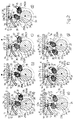
- Figure 2 shows a larger-scale view, with parts removed for clarity, of the Figure 1 device in seven different operating positions;
- Figure 3 shows two graphs illustrating two quantities relative to the motion of a product along the Figure 1 device;
- Figure 4 shows a larger-scale view, with parts removed for clarity, of part of a second preferred embodiment of the rolling device according to the present invention and in three different operating positions.
-
Number 1 in Figure 1 indicates a rolling device forming part of a filter assembly machine 1a, and for connecting, by means of respectivegummed strips 2, the two cigarette portions (not shown) and the intermediate double filter (not shown) of a number ofgroups 3 fed successively todevice 1 by a known feed roller (not shown). -
Device 1 comprises aroller 4 rotated clockwise (in Figure 1) about itsaxis 5 by known drive means (not shown), and at a constant surface speed V1 in relation to aframe 6 parallel to the Figure 1 and 2 planes; and aroller 7 mounted for rotation onframe 6, and rotating anticlockwise (in Figure 1) at substantially the same surface speed asroller 4, and about anaxis 8 parallel toaxis 5.Roller 7 is tangent toroller 4 at atransfer station 9 wheregroups 3 are transferred fromrespective suction seats 10 equally spaced about theperipheral surface 11 ofroller 4, torespective suction seats 10a equally spaced about the peripheral surface ofroller 7. A front portion (in the traveling direction of roller 4) of eachstrip 2 is located betweenrespective group 3 andrespective seat 10, and a rear portion of eachstrip 2 extends rearwards ofrespective group 3 and is maintained contacting theperipheral surface 11 ofroller 4 by known suction means (not shown). -
Device 1 also comprises afixed plate 12 facing a portion ofsurface 11 and defined, on theside facing surface 11, by a curved notched surface parallel tosurface 11 and forming arolling bed 13. Together withsurface 11,rolling bed 13 defines arolling channel 14, the width of which is approximately equal to but no larger than the diameter ofgroups 3, and is larger than the diameter ofgroups 3 if added to the depth ofseat 10, so that agroup 3 housed insideseat 10 could theoretically travel along the whole ofchannel 14 without coming into contact withrolling bed 13. -
Device 1 also comprises arolling initiating unit 15 adjacent toinlet 16 ofchannel 14, and which provides, with substantially no impact, for gradually braking eachgroup 3 upstream frominlet 16, easing it out ofrespective seat 10, and rolling it backwards aboutrespective axis 3a and alongsurface 11, so as to partly wind gummedstrip 2 about the double filter (not shown) and the ends of the two cigarette portions (not shown). -
Device 15 comprises adrum type cam 17 presenting aninner sleeve 18 fitted, by means of akey 19, to ashaft 20 supported in angularly fixed manner onframe 6 and presenting anaxis 21 parallel toaxes profile 22 for a number oftappet rollers 23, each of which is maintainedcontacting profile 22 by a known guide device (not shown), and is mounted for rotation, by means of arespective pin 24 parallel toaxis 21, on one end of arespective rocker arm 25 pivoting, by means of arespective pin 26 parallel topins 24, on adrum 27 coaxial withaxis 21.Drum 27 is fitted in known manner (not shown) to a drive shaft (not shown) in turn fitted throughframe 6 and by whichdrum 27 is rotated anticlockwise (in Figure 1) aboutaxis 21 at an angular speed equal to that ofroller 4, and at a surface speed V2 lower than speed V1. - Each
rocker arm 25 comprises afirst arm 28, a first end of which supportstappet roller 23, and the second end of which is fitted through with anend portion 29 ofpin 26; and a second arm 30 extending radially outwards from the free end ofportion 29, and forming an angle of less than 180° witharm 28. Arm 30 comprises a tooth, the free end of which is defined by asurface 31 parallel topin 26 and sloping towardsaxis 21 from thetip 32 of the front lateral edge of arm 30 with reference to the rotation direction ofdrum 27. -
Profile 22 ofcam 17 comprises a substantially spiral-shaped portion 33 extending over a roughly 330° arc AB - measured anticlockwise, i.e. in the rotation direction of drum 27 - aboutaxis 21 and from a point A with a maximum radius "R", to a point B with a minimum radius "r"; and aconcave portion 34 extending over a roughly 30° arc BA - measured in the rotation direction of drum 27 - and facing and substantially parallel toperipheral surface 11 ofroller 4. By virtue of the shape ofportions rocker arm 25, as it travels anticlockwise (in Figure 1) alongprofile 22 at substantially the same angular speed asdrum 27 and by rotatingdrum 27 aboutaxis 21, rotates anticlockwise by a given arc about the axis ofpin 26 as it travels alongportion 33, and rotates clockwise by the same arc about the axis ofpin 26 as it travels alongportion 34. - Each
rocker arm 25 therefore rotates aboutaxis 21 together withdrum 27, while at the same time oscillating about the rotation axis of 26 in relation todrum 27, so that, for each turn ofdrum 27, eachtip 32 describes a closedpath 35 at a surface speed V3 equal to the sum of two parts: a first part which is constant and substantially equal to the surface speed V2 ofdrum 27 aboutaxis 21; and a second part V4 which is variable and depends on the rotation ofrocker arm 25 about the axis ofpin 26. More specifically, speeds V4 and V2 are in the same direction asroller 23 rolls alongportion 33, and are in opposite directions asroller 23 rolls alongportion 34; andportions roller 23 is tangent to profile 22 at point B, speed V3 reaches a substantially maximum value equal to V1, and, asroller 23 rolls along a given portion ofportion 34, speed V4 assumes the same but opposite value to speed V2 so that speed V3 is zero. - Operation of
rolling device 1 will now be described with reference to Figure 2 which shows a pair ofadjacent rocker arms 25 in seven different positions, one for each of the seven views in Figure 2 indicating fourteen characteristic positions of eachrocker arm 25 aboutaxis 21. For the sake of simplicity, eachrocker arm 25 is indicated by a complex number consisting ofnumber 25 and two letters, the first (A-G) indicating the view referred to, and the second (L-R) indicating the position (to the left or right) of therocker arm 25 referred to in each view. - Also, operation of
rolling device 1 will be described with reference to onerocker arm 25 and onegroup 3, as of the instant in whichtip 32 of the rocker arm 25 - in this case, rocker arm 25AR - is located at a point alongpath 35 upstream from two points C and D at whichpath 35 intersects the extension of the curved surface definingrolling bed 13. -
Roller 23 of rocker arm 25AR rolls, without sliding, along the end portion ofportion 33 ofcam profile 22 preceding point B at whichcam 17 presents a minimum radius "r"; and speed V4 oftip 32 of rocker arm 25AR is in the same direction as speed V2, so that speed V3 is greater than V2 but still less than V1, and rocker arm 25AR rotates anticlockwise (in Figure 2) about the axis ofpin 26. At the same time, the respective group 3 - only visible as of Figure 2d - travels in time withtip 32 towards point C at speed V1 and at an angular speed of zero in relation to itsaxis 3a. - This situation continues until the
rocker arm 25 in question reaches the position of rocker arm 25AL, theroller 23 of which is tangent to camprofile 22 substantially at point B of minimum radius "r", and thetip 32 of which is located between points C and D and travels at a speed V3 which has risen to a maximum value substantially equal to V1. Uponrocker arm 25 reaching the position of rocker arm 25AL, it is joined byrespective group 3 which contacts surface 31 at a speed tending asymptotically towards zero. - At this point, speed V4 is inverted,
rocker arm 25 begins rotating clockwise about the axis ofpin 26, and speed V3 oftip 32 begins to fall so that arm 30 slows downrespective group 3 which, whenrocker arm 25 reaches the position of rocker arm 25BL, is eased out ofrespective seat 10, begins rolling backwards alongsurface 11, and is deformed elastically onsurface 31. - At the next instant, and more specifically upon
rocker arm 25 reaching the position of rocker arm 25CL, the negative speed V4 oftip 32 equals, in absolute value, speed V2, so thattip 32 is positioned stationary in front ofinlet 16 ofrolling channel 14, andgroup 3, by now eased entirely out ofrespective seat 10, reaches its full rolling speed VR, rolls overtip 32 and deforms radially to roll overrocker arm 25 when this reaches the position of 25EL, and rolls with substantially no impact intorolling channel 14. Sincetip 32 of rocker arm 25EL is substantially stationary,group 3 contacts, along diametrically opposite lines,fixed tip 32 on the one side, andsurface 11 traveling at speed V1 on the other, so thataxis 3a ofgroup 3 travels, as shown in Figure 3, at a speed equal to half speed V1. More specifically, due to elastic hysteresis,group 3 reaches its full rolling speed VR an instant beforeaxis 3a reaches speed V1/2 at whichaxis 3a then proceeds along the whole ofchannel 14. - From the foregoing description, and as shown in Figure 3,
rolling device 1 therefore provides, with no impact, for gradually slowing down eachgroup 3 before it enterschannel 14, and so minimizing the stress to whichgroup 3 is subjected. - It should be pointed out, however, that, due to said elastic hysteresis and as shown in Figures 2e and 2f,
groups 3 only regain their outer shape after enteringchannel 14 and being released byrespective rocker arms 25 which, downstream from the position of rocker arm 25EL, engage agroove 36 formed laterally alongplate 12. A remote possibility therefore exists that eachgroup 3, at the start ofchannel 14 and as it regains its shape, may undergo a sufficiently sharp variation in surface speed as to damage it. - To eliminate this possibility, Figure 4 shows a variation wherein arm 30 is replaced by an
arm 37 comprising a substantially L-shaped portion in turn presenting afirst portion 38 connected topin 26 by ascrew 39, and asecond portion 40 extending outwards from the rear end ofportion 38 in the rotation direction of drum 27 (Figure 1) and in turn presenting aninclined end surface 31 similar to that of arm 30. The outer surface ofportion 38 and the front surface ofportion 40 are fitted with a substantiallyrectangular plate 41, an outer edge of which is notched in the same way as rollingbed 13 and defines asurface 42 for receivinggroup 3 once it rolls oversurface 31 ofportion 40, and which is aligned (Figure 4c) withbed 13 before engaginggroove 36, to enablegroup 3 to regain its shape before enteringchannel 14. - In the case of the Figure 4 variation, both the Figure 3 graphs are to be considered shifted to the left, in that each
group 3 reaches its full rolling speed VR and halves its traveling speed before enteringchannel 14.
Claims (9)
- A rolling device for elongated elements (3), particularly for producing tobacco items; the device comprising powered conveyor means (4; 7) presenting a transportation surface (11) with a number of seats (10) for receiving respective elongated elements (3); a plate (12) facing a portion of the transportation surface (11), and presenting a rolling bed (13) defining a rolling channel (14) with said transportation surface (11); and rolling initiating means (15) located at the inlet (16) of said rolling channel (16); characterized in that said initiating means (15) comprise braking means (25) for successively engaging and gradually reducing the speed of said elongated elements (3) from a first speed (V1) at which said conveyor means (4) travel, to a second speed (V1/2) at which the elongated elements (3) travel along said channel (14).
- A device as claimed in Claim 1, characterized in that said braking means (25) comprise at least a brake element (30; 37) traveling cyclically along a path (35), a given portion (CD) of which upstream from said inlet (16) interferes with a respective said elongated element (3); activating means (27) and control means (17) being provided for varying the speed of said brake element (30; 37) between a maximum value and a minimum value defining a speed range comprising a value equal to said first speed (V1) and a zero value.
- A device as claimed in Claim 2, characterized in that said path (35) is substantially circular.
- A device as claimed in Claim 3, characterized in that said conveyor means (4) comprise a powered roller (4) rotating about a first axis (5) and presenting a number of peripheral suction seats (10) parallel to said first axis (5); said path (35) extending about a second axis (21) parallel to the first axis (5).
- A device as claimed in Claim 4, characterized in that said activating means (27) comprise a powered drum (27) rotating about said second axis (21); said brake element (30; 37) being connected to said drum (27) so as to rotate with it about said second axis (21); said roller (4) rotating said seats (10) about the first axis (5) at a first linear speed (V1); and said drum (27) rotating in the opposite direction to said roller (4), and rotating said brake element (30; 37) about the second axis (21) at a second linear speed (V2) lower than the first speed (V1).
- A device as claimed in Claim 5, characterized in that said brake element (30; 37) forms part of a rocker arm (25) fitted to said drum (27) so as to rotate in relation to the drum (27) about a third axis (26) parallel to the second axis (21); said control means (17) comprising a fixed cam (17) connected to said rocker arm (25) and for controlling the position of the brake element (30; 37) about said third axis (26).
- A device as claimed in Claim 6, characterized in that said cam presents a profile (22) in turn comprising a first portion (33) cooperating with said rocker arm (25) so that the speed (V4) of said brake element (30; 37) about said third axis (26) is in the same direction as said second speed (V2), and a second portion (34) cooperating with said rocker arm (25) so that the speed (V4) of said brake element (30; 37) about said third axis (26) is in the opposite direction to said second speed (V2); the brake element (30; 37) traveling, in use, along said given portion (CD) of interference when said rocker arm (25) cooperates with said second portion (34) of said profile (22).
- A device as claimed in Claim 7, characterized in that said brake element is defined by an arm (30; 37) of said rocker arm (25), and comprises a tooth (30; 40) presenting a surface (31) which is positioned contacting a respective said elongated element (3) along said given portion (CD) of interference.
- A device as claimed in Claim 8, characterized in that said arm (37) also comprises a rolling surface (42) to the front of said tooth (40) in the rotation direction of said drum (27).
Applications Claiming Priority (2)
| Application Number | Priority Date | Filing Date | Title |
|---|---|---|---|
| IT94BO000276A ITBO940276A1 (en) | 1994-06-14 | 1994-06-14 | ROLLING DEVICE FOR EXTENDED ELEMENTS, ESPECIALLY FOR THE PRODUCTION OF SMOKE ARTICLES |
| ITBO940276 | 1994-06-14 |
Publications (2)
| Publication Number | Publication Date |
|---|---|
| EP0687424A1 true EP0687424A1 (en) | 1995-12-20 |
| EP0687424B1 EP0687424B1 (en) | 1998-04-08 |
Family
ID=11339880
Family Applications (1)
| Application Number | Title | Priority Date | Filing Date |
|---|---|---|---|
| EP95108669A Expired - Lifetime EP0687424B1 (en) | 1994-06-14 | 1995-06-06 | Device for rolling elongated elements, particularly for producing tobacco items |
Country Status (5)
| Country | Link |
|---|---|
| US (1) | US5577518A (en) |
| EP (1) | EP0687424B1 (en) |
| JP (1) | JPH0851969A (en) |
| DE (1) | DE69501978T2 (en) |
| IT (1) | ITBO940276A1 (en) |
Cited By (6)
| Publication number | Priority date | Publication date | Assignee | Title |
|---|---|---|---|---|
| EP0821887A1 (en) * | 1996-08-03 | 1998-02-04 | Hauni Maschinenbau Aktiengesellschaft | Method and device for assembling smoking articles with an adhesive connecting strip |
| EP1055376A1 (en) * | 1999-05-27 | 2000-11-29 | Hauni Maschinenbau AG | Apparatus for rolling rod-like articles |
| EP1588632A1 (en) | 2002-10-22 | 2005-10-26 | Hauni Maschinenbau AG | Method and device for conveying smoking articles |
| US7089944B2 (en) | 2002-03-12 | 2006-08-15 | Hauni Maschinenbau Ag | Process and device for connecting smoking articles |
| WO2017203255A1 (en) * | 2016-05-27 | 2017-11-30 | British American Tobacco (Investments) Limited | Apparatus and method for manufacturing tobacco industry products |
| US11540558B2 (en) | 2016-05-27 | 2023-01-03 | British American Tobacco (Investments) Limited | Apparatus and method for manufacturing tobacco industry products |
Families Citing this family (15)
| Publication number | Priority date | Publication date | Assignee | Title |
|---|---|---|---|---|
| WO1998057557A1 (en) * | 1996-04-17 | 1998-12-23 | Japan Tobacco Inc. | Filter mounting apparatus |
| DE19857576A1 (en) * | 1998-12-14 | 2000-06-15 | Hauni Maschinenbau Ag | Device for wrapping papers around rod-shaped objects |
| DE10004906A1 (en) * | 2000-02-04 | 2001-08-09 | Hauni Maschinenbau Ag | A method by which filter cigarettes are manufactured with perforations in a single rolling together with the paper wrapping operation |
| DE10112336A1 (en) * | 2001-03-13 | 2002-09-19 | Hauni Maschinenbau Ag | Method and device for wrapping rod-shaped articles with wrapping papers |
| DE102004042106B3 (en) * | 2004-08-30 | 2006-02-09 | Hauni Maschinenbau Ag | Device for rolling rod-like tobacco components comprises a front roll surface provided in front of a bar in the rotation direction of a web wheel |
| DE102005019681B4 (en) | 2005-04-26 | 2011-11-10 | Hauni Maschinenbau Ag | Rolling of rod-shaped smoking article groups |
| TWI637696B (en) * | 2013-01-31 | 2018-10-11 | 菲利浦莫里斯製品股份有限公司 | Apparatus and method for wrapping a sheet of wrapping material around a rod-shaped article or around a plurality of linearly arranged substantially cylindrical segments; and rolling device for use in the apparatus |
| GB2521167A (en) * | 2013-12-11 | 2015-06-17 | British American Tobacco Co | An apparatus for forming a circumferential slit in a tobacco industry rod article |
| GB201406267D0 (en) * | 2014-04-08 | 2014-05-21 | British American Tobacco Co | A rolling drum assembly for use in smoking article manufacture |
| EP3131423A1 (en) | 2014-04-14 | 2017-02-22 | Altria Client Services LLC | Rotatable drum and method and system using the same for the automated production of e-vapor devices |
| EP3131424A2 (en) | 2014-04-14 | 2017-02-22 | Altria Client Services LLC | Method and system for the automated production of e-vapor devices |
| GB201408922D0 (en) * | 2014-05-20 | 2014-07-02 | British American Tobacco Co | Apparatus comprising a tipping paper suction drum |
| CN106793837A (en) | 2014-10-16 | 2017-05-31 | 奥驰亚客户服务有限责任公司 | Assembling drum, system and its application method for automated production electronic cigarette device |
| US10858137B2 (en) | 2014-12-19 | 2020-12-08 | Altria Client Services Llc | System and method for applying a label for the automated production of e-vapor devices |
| DE102021124107A1 (en) | 2021-09-17 | 2023-03-23 | Körber Technologies Gmbh | Rolling of stick-shaped articles in the tobacco processing industry |
Citations (3)
| Publication number | Priority date | Publication date | Assignee | Title |
|---|---|---|---|---|
| US3093143A (en) * | 1960-02-04 | 1963-06-11 | Hauni Werke Koerber & Co Kg | Device for wrapping a connecting band around axially aligned rod-shaped articles |
| US3527234A (en) | 1966-05-20 | 1970-09-08 | Hauni Werke Koerber & Co Kg | Apparatus for convoluting uniting bands around rod-shaped articles |
| US4825882A (en) | 1987-01-31 | 1989-05-02 | Korber Ag | Apparatus for rolling uniting bands around groups of rod-shaped articles |
Family Cites Families (10)
| Publication number | Priority date | Publication date | Assignee | Title |
|---|---|---|---|---|
| US3483873A (en) * | 1968-02-14 | 1969-12-16 | Hauni Werke Koerber & Co Kg | Apparatus for making holes in tobacco rods or the like |
| FR2453809A1 (en) * | 1979-04-10 | 1980-11-07 | Transac Develop Transactions A | METHOD AND DEVICE FOR SEPARATING AND EXTRACTING ONE TO ONE OF STACKED SHEETS |
| US4451027A (en) * | 1980-01-09 | 1984-05-29 | Burroughs Corp. | Constant spacing document feeder |
| DE3029458A1 (en) * | 1980-08-02 | 1982-03-04 | Kleindienst Gmbh & Co Kg, 8900 Augsburg | TRANSPORT AND ALIGNMENT DEVICE FOR SEPARATING DOCUMENTS, IN PARTICULAR DATA CARRIERS |
| US4437658A (en) * | 1981-07-30 | 1984-03-20 | Profold, Inc. | Bottom sheet feed system |
| JPS58109334A (en) * | 1981-12-21 | 1983-06-29 | Minolta Camera Co Ltd | Sheet feeder |
| US5024242A (en) * | 1989-04-27 | 1991-06-18 | Philip Morris Incorporated | Methods and apparatus for making multiple component smoking articles |
| JPH05201572A (en) * | 1991-07-29 | 1993-08-10 | Riso Kagaku Corp | Paper separating type paper feeding device |
| US5349968A (en) * | 1992-07-22 | 1994-09-27 | G.D Societa' Per Azioni | Method of producing filter-tipped cigarettes |
| IT1259802B (en) * | 1992-11-20 | 1996-03-26 | Gd Spa | ROLLING DEVICE FOR FILTER FEEDER MACHINES. |
-
1994
- 1994-06-14 IT IT94BO000276A patent/ITBO940276A1/en unknown
-
1995
- 1995-06-05 US US08/473,118 patent/US5577518A/en not_active Expired - Fee Related
- 1995-06-06 EP EP95108669A patent/EP0687424B1/en not_active Expired - Lifetime
- 1995-06-06 DE DE69501978T patent/DE69501978T2/en not_active Expired - Fee Related
- 1995-06-14 JP JP7147460A patent/JPH0851969A/en active Pending
Patent Citations (3)
| Publication number | Priority date | Publication date | Assignee | Title |
|---|---|---|---|---|
| US3093143A (en) * | 1960-02-04 | 1963-06-11 | Hauni Werke Koerber & Co Kg | Device for wrapping a connecting band around axially aligned rod-shaped articles |
| US3527234A (en) | 1966-05-20 | 1970-09-08 | Hauni Werke Koerber & Co Kg | Apparatus for convoluting uniting bands around rod-shaped articles |
| US4825882A (en) | 1987-01-31 | 1989-05-02 | Korber Ag | Apparatus for rolling uniting bands around groups of rod-shaped articles |
Cited By (8)
| Publication number | Priority date | Publication date | Assignee | Title |
|---|---|---|---|---|
| EP0821887A1 (en) * | 1996-08-03 | 1998-02-04 | Hauni Maschinenbau Aktiengesellschaft | Method and device for assembling smoking articles with an adhesive connecting strip |
| EP1055376A1 (en) * | 1999-05-27 | 2000-11-29 | Hauni Maschinenbau AG | Apparatus for rolling rod-like articles |
| US7089944B2 (en) | 2002-03-12 | 2006-08-15 | Hauni Maschinenbau Ag | Process and device for connecting smoking articles |
| EP1588632A1 (en) | 2002-10-22 | 2005-10-26 | Hauni Maschinenbau AG | Method and device for conveying smoking articles |
| WO2017203255A1 (en) * | 2016-05-27 | 2017-11-30 | British American Tobacco (Investments) Limited | Apparatus and method for manufacturing tobacco industry products |
| US11252990B2 (en) | 2016-05-27 | 2022-02-22 | British American Tobacco (Investments) Limited | Apparatus and method for manufacturing tobacco industry products |
| US11540558B2 (en) | 2016-05-27 | 2023-01-03 | British American Tobacco (Investments) Limited | Apparatus and method for manufacturing tobacco industry products |
| US12108782B2 (en) | 2016-05-27 | 2024-10-08 | British American Tobacco (Investments) Limited | Apparatus and method for manufacturing tobacco industry products |
Also Published As
| Publication number | Publication date |
|---|---|
| US5577518A (en) | 1996-11-26 |
| DE69501978T2 (en) | 1998-10-08 |
| ITBO940276A1 (en) | 1995-12-14 |
| ITBO940276A0 (en) | 1994-06-14 |
| JPH0851969A (en) | 1996-02-27 |
| DE69501978D1 (en) | 1998-05-14 |
| EP0687424B1 (en) | 1998-04-08 |
Similar Documents
| Publication | Publication Date | Title |
|---|---|---|
| EP0687424B1 (en) | Device for rolling elongated elements, particularly for producing tobacco items | |
| US3987605A (en) | Rotary article transfer apparatus | |
| EP0723430B1 (en) | An apparatus and process for cyclically accelerating and decelerating a strip of material | |
| US8647459B2 (en) | Method and equipment for preparing and applying folded leaflets | |
| US3546047A (en) | High speed labeling device | |
| GB1560748A (en) | Conveyor device for conveying rod-like articles of the tobacco-processing industry | |
| US4995223A (en) | Continuous wrapping machine | |
| EP0682881B1 (en) | Unit for transferring cigarette portions from a dual rod cigarette manufacturing machine to a filter assembly machine | |
| EP0829435A1 (en) | Product conveying unit | |
| US5806289A (en) | Continuous cigarette packing machine | |
| US4603534A (en) | Apparatus for wrapping articles, especially cigarette groups | |
| US5024046A (en) | Method and device for wrapping cylindrical products | |
| EP0795472B1 (en) | Product wrapping method | |
| US4745932A (en) | Filter assembly machine | |
| EP0654329A1 (en) | Method and device for scissor cutting strip material | |
| US6390099B1 (en) | Apparatus for convoluting strips around groups of coaxial rod-shaped articles | |
| EP0599162B1 (en) | Rolling device for filter assembly machines | |
| GB2277507A (en) | Folding apparatus for folding wrappers around articles | |
| GB2277727A (en) | Pitch reducing rotary conveyor | |
| US6139009A (en) | Device and process for delivering imbricated products | |
| US5246098A (en) | Output conveyor unit for rigid hinged-lid cigarette packing machines | |
| EP0806347B1 (en) | Method and device for folding end portions of tubular wrappings | |
| US4644961A (en) | Machine for manufacturing filter-tipped cigarettes | |
| EP0573944A1 (en) | Wrapping material feed and cutting device for product wrapping machines | |
| EP0787651A1 (en) | Method for supplying sheets of wrapping material |
Legal Events
| Date | Code | Title | Description |
|---|---|---|---|
| PUAI | Public reference made under article 153(3) epc to a published international application that has entered the european phase |
Free format text: ORIGINAL CODE: 0009012 |
|
| AK | Designated contracting states |
Kind code of ref document: A1 Designated state(s): DE FR GB IT |
|
| 17P | Request for examination filed |
Effective date: 19951102 |
|
| GRAG | Despatch of communication of intention to grant |
Free format text: ORIGINAL CODE: EPIDOS AGRA |
|
| 17Q | First examination report despatched |
Effective date: 19970812 |
|
| GRAG | Despatch of communication of intention to grant |
Free format text: ORIGINAL CODE: EPIDOS AGRA |
|
| GRAH | Despatch of communication of intention to grant a patent |
Free format text: ORIGINAL CODE: EPIDOS IGRA |
|
| GRAH | Despatch of communication of intention to grant a patent |
Free format text: ORIGINAL CODE: EPIDOS IGRA |
|
| GRAA | (expected) grant |
Free format text: ORIGINAL CODE: 0009210 |
|
| AK | Designated contracting states |
Kind code of ref document: B1 Designated state(s): DE FR GB IT |
|
| ITF | It: translation for a ep patent filed | ||
| REF | Corresponds to: |
Ref document number: 69501978 Country of ref document: DE Date of ref document: 19980514 |
|
| ET | Fr: translation filed | ||
| PLBE | No opposition filed within time limit |
Free format text: ORIGINAL CODE: 0009261 |
|
| STAA | Information on the status of an ep patent application or granted ep patent |
Free format text: STATUS: NO OPPOSITION FILED WITHIN TIME LIMIT |
|
| 26N | No opposition filed | ||
| PGFP | Annual fee paid to national office [announced via postgrant information from national office to epo] |
Ref country code: FR Payment date: 19990421 Year of fee payment: 5 |
|
| PGFP | Annual fee paid to national office [announced via postgrant information from national office to epo] |
Ref country code: DE Payment date: 19990531 Year of fee payment: 5 |
|
| PGFP | Annual fee paid to national office [announced via postgrant information from national office to epo] |
Ref country code: GB Payment date: 19990628 Year of fee payment: 5 |
|
| PG25 | Lapsed in a contracting state [announced via postgrant information from national office to epo] |
Ref country code: GB Free format text: LAPSE BECAUSE OF NON-PAYMENT OF DUE FEES Effective date: 20000606 |
|
| GBPC | Gb: european patent ceased through non-payment of renewal fee |
Effective date: 20000606 |
|
| PG25 | Lapsed in a contracting state [announced via postgrant information from national office to epo] |
Ref country code: FR Free format text: LAPSE BECAUSE OF NON-PAYMENT OF DUE FEES Effective date: 20010228 |
|
| REG | Reference to a national code |
Ref country code: FR Ref legal event code: ST |
|
| PG25 | Lapsed in a contracting state [announced via postgrant information from national office to epo] |
Ref country code: DE Free format text: LAPSE BECAUSE OF NON-PAYMENT OF DUE FEES Effective date: 20010403 |
|
| PG25 | Lapsed in a contracting state [announced via postgrant information from national office to epo] |
Ref country code: IT Free format text: LAPSE BECAUSE OF NON-PAYMENT OF DUE FEES;WARNING: LAPSES OF ITALIAN PATENTS WITH EFFECTIVE DATE BEFORE 2007 MAY HAVE OCCURRED AT ANY TIME BEFORE 2007. THE CORRECT EFFECTIVE DATE MAY BE DIFFERENT FROM THE ONE RECORDED. Effective date: 20050606 |