EP0687552B1 - Maschine zur Herstellung einer mindestens einseitig kaschierten Wellpappebahn - Google Patents
Maschine zur Herstellung einer mindestens einseitig kaschierten Wellpappebahn Download PDFInfo
- Publication number
- EP0687552B1 EP0687552B1 EP95108699A EP95108699A EP0687552B1 EP 0687552 B1 EP0687552 B1 EP 0687552B1 EP 95108699 A EP95108699 A EP 95108699A EP 95108699 A EP95108699 A EP 95108699A EP 0687552 B1 EP0687552 B1 EP 0687552B1
- Authority
- EP
- European Patent Office
- Prior art keywords
- machine according
- tensioning
- roller
- pressing
- rings
- Prior art date
- Legal status (The legal status is an assumption and is not a legal conclusion. Google has not performed a legal analysis and makes no representation as to the accuracy of the status listed.)
- Expired - Lifetime
Links
- 238000004519 manufacturing process Methods 0.000 title claims 2
- 239000003292 glue Substances 0.000 claims description 5
- 229920003023 plastic Polymers 0.000 claims description 5
- 239000004033 plastic Substances 0.000 claims description 5
- 238000004026 adhesive bonding Methods 0.000 claims 1
- 239000000123 paper Substances 0.000 description 8
- 229910000831 Steel Inorganic materials 0.000 description 2
- 230000000694 effects Effects 0.000 description 2
- 238000010030 laminating Methods 0.000 description 2
- 239000010959 steel Substances 0.000 description 2
- 238000010276 construction Methods 0.000 description 1
- 238000011161 development Methods 0.000 description 1
- 230000018109 developmental process Effects 0.000 description 1
- 238000010438 heat treatment Methods 0.000 description 1
- 238000002372 labelling Methods 0.000 description 1
- 239000000463 material Substances 0.000 description 1
Images


Classifications
-
- B—PERFORMING OPERATIONS; TRANSPORTING
- B31—MAKING ARTICLES OF PAPER, CARDBOARD OR MATERIAL WORKED IN A MANNER ANALOGOUS TO PAPER; WORKING PAPER, CARDBOARD OR MATERIAL WORKED IN A MANNER ANALOGOUS TO PAPER
- B31F—MECHANICAL WORKING OR DEFORMATION OF PAPER, CARDBOARD OR MATERIAL WORKED IN A MANNER ANALOGOUS TO PAPER
- B31F1/00—Mechanical deformation without removing material, e.g. in combination with laminating
- B31F1/20—Corrugating; Corrugating combined with laminating to other layers
- B31F1/24—Making webs in which the channel of each corrugation is transverse to the web feed
- B31F1/26—Making webs in which the channel of each corrugation is transverse to the web feed by interengaging toothed cylinders cylinder constructions
- B31F1/28—Making webs in which the channel of each corrugation is transverse to the web feed by interengaging toothed cylinders cylinder constructions combined with uniting the corrugated webs to flat webs ; Making double-faced corrugated cardboard
- B31F1/2845—Details, e.g. provisions for drying, moistening, pressing
- B31F1/2877—Pressing means for bringing facer sheet and corrugated webs into contact or keeping them in contact, e.g. rolls, belts
-
- Y—GENERAL TAGGING OF NEW TECHNOLOGICAL DEVELOPMENTS; GENERAL TAGGING OF CROSS-SECTIONAL TECHNOLOGIES SPANNING OVER SEVERAL SECTIONS OF THE IPC; TECHNICAL SUBJECTS COVERED BY FORMER USPC CROSS-REFERENCE ART COLLECTIONS [XRACs] AND DIGESTS
- Y10—TECHNICAL SUBJECTS COVERED BY FORMER USPC
- Y10T—TECHNICAL SUBJECTS COVERED BY FORMER US CLASSIFICATION
- Y10T156/00—Adhesive bonding and miscellaneous chemical manufacture
- Y10T156/10—Methods of surface bonding and/or assembly therefor
- Y10T156/1002—Methods of surface bonding and/or assembly therefor with permanent bending or reshaping or surface deformation of self sustaining lamina
- Y10T156/1025—Methods of surface bonding and/or assembly therefor with permanent bending or reshaping or surface deformation of self sustaining lamina to form undulated to corrugated sheet and securing to base with parts of shaped areas out of contact
Definitions
- the invention relates to a machine according to the preamble of the claim 1.
- EP 0 492 310 A1 Such a machine is known from EP 0 492 310 A1.
- the on Corrugated webs produced in such machines are between 1.2 and 2.8 m and usually 2.5 m wide. There are therefore considerable ones Difficulty finding an even spread across the full width of the paper web To achieve pressure by the pressure belt, because the deflection roller deflects.
- EP 0 492 310 A1 therefore provides for the deflecting roller perform crowned so as to deflect the deflection roller compensate. The effort for this is considerable.
- the pressure band is subjected to torsional effects. Still is the replacement of a damaged pressure tape extremely time and expensive.
- At least one deflection roller is stored in bearings, each by means of a piston-cylinder drive Clamping drive can be moved.
- a roller in particular a counter-pressure roller a pair of rollers for conveying and / or processing a material web known that a stationary roller carrier and Movable roll shell has.
- Between the roller carrier and the Roller jacket is at least one roller tube comprising the roller carrier arranged. This roller tube is articulated to a limited extent on the roller carrier.
- the roller jacket is rotatably mounted on it. Through this configuration is achieved that the counter-pressure roller no external Swivel levers needed more.
- the invention has for its object a machine of the generic type Kind in such a way that the pressing of the liner in the pressing area takes place in a particularly simple and reliable manner.
- the pressure belt is guided cleanly in a simple manner can be.
- the belt can be stretched differently across its width be how it is for the distribution of the contact forces or the contact pressure across the width of the corrugated cardboard web is desired.
- the tensioning devices can be in the form of a spherical tensioning roller receive, so that good guidance of the pressure belt is guaranteed is.
- different strains of the Pressure band compensated due to different heating will.
- a lower corrugating roller 2 and an upper one Corrugated roller 3 rotatably supported by means of shafts 4, 5. They point to each other parallel axes 6, 7. They are with them on their cylinder surfaces Corrugations 8, 9 extending parallel to the axes 6, 7, which Comb in the contact area 10 of the two corrugated rollers 2, 3.
- One of the corrugating rollers 2, 3, usually the upper corrugating roller 3 is driven in the direction of rotation 12, while the other corrugating roller, So usually the lower corrugating roller 2 in the direction of rotation 11 of the other corrugating roller 3 is taken.
- a glue application device 13 is arranged downstream of the contact area 10 Arranged machine frame 1, which has a glue application roller 14, which is deliverable against the corrugation 9 of the upper corrugating roller 3.
- the Applicator roller 14 is rotatable about an axis 15.
- a pressure device 16 is located in the upper area of the upper corrugating roller provided that a deflecting roller 17, a tension roller 18 and a pressure belt 19 has.
- the deflection roller 17 is by means of shaft journals 20 in bearings 21 of the machine frame 1 rotatably mounted about an axis 22 and is from the upper Corrugated roller 3 taken.
- the tension roller 18 has a stationary and non-rotatable in the machine frame 1 supported cylindrical roller carrier 23 on which several Support rings 24 side by side and non-rotatable relative to the roller carrier 23 are arranged.
- a roller casing ring 25 is free on each support ring 24 rotatably mounted, for which he on the respective support ring 24 by means of a Slide or roller bearing 26 is supported.
- About roller-jacket rings 25 is the pressure belt 19 out.
- the pressure band 19 lies over a wrap angle a of about 90 ° against the corrugation 9 of the upper corrugating roller 3 starts and runs in the same direction as the direction of the arrow 27 um.
- the pressure belt 19 runs from the upper corrugating roller 3 corresponding to the discharge tangent 28, which is identical to the inlet tangent of the pressure belt 19 on the tension roller 18.
- the support rings 24 and with them the roller jacket rings 25 are on the Roller carrier 23 can be displaced parallel to the outlet tangent 28 of the pressure belt 19, individually.
- the roller carrier 23 Mounted parallel to the axis 29 bearing strips 30, against which in turn Guide strips 31 abut the inside of each support ring 24 are attached.
- sliding bearings 32 are formed by means of which each roller jacket ring 25 on the roller carrier 23 transversely to the drain tangent 28 immovable and essentially free of play and is displaceable parallel to the drain tangent 28 in the direction 33.
- a clamping drive 35 is arranged, for example, by a pressure cushion 36 can be formed via a pressure medium channel 37 in the roller carrier 23 is connected to a pressure medium source, not shown.
- the pressure pad 36 or the pressure pad 36 of each support ring 24 is a own pressure medium channel 37 in the roller carrier 23 assigned to each pressurized independently of the other pressure medium channels 37 can be.
- the pressure medium will to be compressed air.
- the tensioning drive moves 35 when pressurized with pressure, the support ring 24 in the direction 33. Due to the described design, each roller casing ring forms 25 for the pressure belt 19, a tension roller 18, so that the pressure belt 19th can be stretched differently across its width.
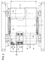
- the width b of the individual roller jacket rings 25 is usually not larger than 400 mm and usually between 100 mm to 400 mm. Of the Distance c between adjacent roller-jacket rings 25 is so small as possible in terms of construction, but generally not larger than 10 mm.
- the total width d of the pressure belt 19 and thus the tension roller 18 is usually 1.2 to 2.8 m and usually 2.5 m.
- the tensioning roller 18 'shown in cross section in FIG. 3 differs itself from the tensioning roller 18 shown in FIGS. 1 and 2 by the The way in which the support rings 24 are supported or supported on the roller carrier 23 are.
- the support rings 24 are not means Sliding bearings are slidably supported on the roller support 23; much more are the support rings 24 each by means of a joint 38 on the roller carrier 23 attached, the pivot axis 39 parallel to the axis 29 of the roller carrier 23 runs.
- the joint 38 with the pivot axis 39 is opposite the vertical by the angle a / 2, in this case 45 ° arranged pivoted relative to the vertical, so that the support rings 24 with the roller jacket rings 25 during the small pivoting movements that occur be pivoted approximately exactly in the direction of 33. Also So here the movement of the support rings 24 with the roller-jacket rings takes place 25 parallel to the drain tangent 28.
- the device works as follows:
- a paper web 40 runs in, through the corrugations 8, 9 is provided with a corrugation 41.
- the tips 42 of the respective curl 41 are provided with glue in the glue application device 13.
- the remaining Areas of the corrugated paper web 40 are not glued.
- a laminating web 43 which is also made Paper exists and has the same width as the paper web 40. Die Width of the paper web 40 is at most equal to the total width d of the pressure belt 19.
- This laminating web 43 is against the outside 44 of the Pressure tape 19 introduced and in the by the wrap angle a defined pressure area 45 of the pressure band 19 against the tips 42 the corrugated lying in the corrugation 9 of the upper corrugating roller 3 Paper web 40 pressed and connected to this.
- the pressure band 19 presses the liner 43 against with its smooth outside 44 the corrugated paper web 40.
- the fully glued corrugated cardboard laminated on one side with a liner 43 46 runs in the direction of the drain tangent 28 together with the Pressure belt 19 from the upper corrugating roller 3 and is with the pressure belt 19 partially guided around the tension roller 18 or 18 '. From there it is fed to a take-up device in the pull-off direction 47.
- the individual roller jacket rings 25 are adjusted during operation so that the belt tension in the pressure belt 19 is constant or above whose width has a desired course.
- the tension roller 18 in its wrapped around by the pressure belt 19 In Fig. 1, left, recognizable area overall approximately a spherical shape receive, whereby the pressure belt 19 exactly laterally on the tension roller 18 is performed.
- the corrugated cardboard web 46 can also be expedient to move the corrugated cardboard web 46 in the direction the drain tangent 28 to deduct from the corrugating roller 3 and not around to guide the tensioning roller 18 or 18 ', but to continue in a straight line. It is then a deflection roller, not shown, from the Machine led out.
- the tube 48 does not have to go over the roller jacket rings 25 are pushed; if necessary, it can also directly affect the Slide or roller bearings 26 are pushed, i.e. in this case the roller jacket rings 25 over the full width of the pressing device 16 formed by a one-piece, elastically flexible tube made of plastic. It is crucial that the tube 48 over its full length of up to 2.5 m can be deformed by a few millimeters, usually not more than 1 mm is. So it can also be a thin steel tube or trade a slotted steel tube.
- the pressure band 19 is advantageously made of plastic so that it can be stretched differently across its width.
Landscapes
- Engineering & Computer Science (AREA)
- Mechanical Engineering (AREA)
- Machines For Manufacturing Corrugated Board In Mechanical Paper-Making Processes (AREA)
Description
- Fig. 1
- eine Maschine zur Herstellung einer einseitig kaschierten Wellpappebahn in einer vertikalen, teilweise aufgebrochenen Darstellung,
- Fig. 2
- eine Draufsicht auf die Maschine nach Fig. 1 gemäß dem Sichtpfeil II in Fig. 1,
- Fig. 3
- einen Querschnitt durch eine Spannwalze in abgewandelter Ausführung und
- Fig. 4
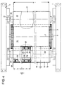
- eine Draufsicht auf eine abgewandelte Ausführungsform einer Maschine in einer Darstellung entsprechend Fig. 2.
Claims (14)
- Maschine zur Herstellung einer mindestens einseitig kaschierten Wellpappebahn (46),dadurch gekennzeichnet, daß die Anpreß-Einrichtung (16) über die volle Breite (d) des Anpreßbandes (19) nebeneinander mehrere Spanneinrichtungen aufweist.mit zwei Riffelwalzen (2, 3) zur Erzeugung einer Wellung (41) an einer Papierbahn (40),mit einer Leimauftragseinrichtung (13) zum Auftrag von Leim auf die Spitzen (42) der Wellung (41) der gewellten Papierbahn (40),mit einer Anpreß-Einrichtung (16) zum Anpressen einer Kaschierbahn (43) an die mit Leim versehenen Spitzen (42) der an einer der Riffelwalzen (3) über einen Anpreßbereich (45) anliegenden gewellten Papierbahn (40), wobei die Anpreß-Einrichtung (16) ein endloses Anpreßband aufweist, das über eine Umlenkwalze (17) und eine weitere Walze (18, 18') geführt ist, und das über den Anpreßbereich (45) gegen die Riffelwalze (3) gedrückt ist und wobei die Anpreß-Einrichtung (16) eine Spanneinrichtung für das Anpreßband aufweist,
- Maschine nach Anspruch 1, dadurch gekennzeichnet, daß das Anpreßband (19) über mehrere Spannwalzen geführt ist, die quer zu ihrer Achse (29) bewegbar sind.
- Maschine nach Anspruch 2, dadurch gekennzeichnet, daß die Spannwalzen auf einem gemeinsamen ortsfesten Walzenträger (23) bewegbar gelagert sind.
- Maschine nach Anspruch 2 oder 3, dadurch gekennzeichnet, daß die Spannwalzen (Walzen-Mantelringe 25) etwa parallel zur Ablaufrichtung (Ablauftangente 28) der Wellpappebahn (46) aus dem Anpreßbereich (45) bewegbar sind.
- Maschine nach Anspruch 3 oder 4, dadurch gekennzeichnet, daß auf dem Walzenträger (23) Tragringe (24) verschiebbar gelagert sind, auf denen jeweils die Spannwalzen (Walzen-Mantelringe 25) drehbar gelagert sind.
- Maschine nach Anspruch 5, dadurch gekennzeichnet, daß die Tragringe (24) mittels Schiebelagern (32) auf dem Walzenträger (23) gelagert sind.
- Maschine nach Anspruch 3 oder 4, dadurch gekennzeichnet, daß auf dem Walzenträger (23) Tragringe (24) verschwenkbar abgelagert sind, auf denen jeweils die Spannwalzen (Walzen-Mantelringe 25) drehbar gelagert sind.
- Maschine nach Anspruch 5 oder 6, dadurch gekennzeichnet, daß zwischen Walzenträger (23) und jedem Tragring (24) ein Spann-Antrieb (35) angeordnet ist.
- Maschine nach Anspruch 8, dadurch gekennzeichnet, daß der Spann-Antrieb (35) durch mindestens ein mit Druckmittel beaufschlagbares Druck-Kissen (36) gebildet ist.
- Maschine nach einem der Ansprüche 4 bis 9, dadurch gekennzeichnet, daß für die Breite (b) der Spannwalzen (Walzen-Mantelringe 25) gilt: b < 400 mm, und bevorzugt 100 mm < b < 400 mm.
- Maschine nach einem der Ansprüche 4 bis 10, dadurch gekennzeichnet, daß für den Abstand (c) zweier benachbarter Spannwalzen (Walzen-Mantelringe 25) gilt: c < 10 mm.
- Maschine nach einem der Ansprüche 1 bis 11, dadurch gekennzeichnet, daß zwischen den Spanneinrichtungen und dem Anpreßband (19) ein die Spanneinrichtungen einhüllendes, elastisch nachgiebig verformbares Rohr (48) angeordnet ist.
- Maschine nach Anspruch 12, dadurch gekennzeichnet, daß das Rohr (48) aus Kunststoff besteht.
- Maschine nach einem der Ansprüche 1 bis 13, dadurch gekennzeichnet, daß das Anpreßband (19) aus Kunststoff besteht.
Applications Claiming Priority (2)
| Application Number | Priority Date | Filing Date | Title |
|---|---|---|---|
| DE4420726 | 1994-06-16 | ||
| DE4420726A DE4420726A1 (de) | 1994-06-16 | 1994-06-16 | Maschine zur Herstellung einer mindestens einseitig kaschierten Wellpappebahn |
Publications (3)
| Publication Number | Publication Date |
|---|---|
| EP0687552A2 EP0687552A2 (de) | 1995-12-20 |
| EP0687552A3 EP0687552A3 (de) | 1996-04-17 |
| EP0687552B1 true EP0687552B1 (de) | 1998-03-04 |
Family
ID=6520531
Family Applications (1)
| Application Number | Title | Priority Date | Filing Date |
|---|---|---|---|
| EP95108699A Expired - Lifetime EP0687552B1 (de) | 1994-06-16 | 1995-06-07 | Maschine zur Herstellung einer mindestens einseitig kaschierten Wellpappebahn |
Country Status (3)
| Country | Link |
|---|---|
| US (1) | US5632850A (de) |
| EP (1) | EP0687552B1 (de) |
| DE (2) | DE4420726A1 (de) |
Families Citing this family (29)
| Publication number | Priority date | Publication date | Assignee | Title |
|---|---|---|---|---|
| US5951816A (en) * | 1996-03-26 | 1999-09-14 | Marquip, Inc. | Single facer with small intermediate corrugating roll |
| IT1298011B1 (it) * | 1997-07-11 | 1999-12-20 | Agnati Spa | Gruppo ondulare, in particolare per fogli o nastri di materiale cartaceo, o simili. |
| US5951817A (en) * | 1997-08-14 | 1999-09-14 | United Container Machinery, Inc. | Single facer having an auxiliary nip |
| DE19751162A1 (de) * | 1997-11-19 | 1999-05-20 | Bhs Corr Masch & Anlagenbau | Maschine zur Herstellung einer mindestens einseitig kaschierten Wellpappebahn |
| DE19955917A1 (de) * | 1999-11-20 | 2001-05-23 | Bhs Corr Masch & Anlagenbau | Anlage zur Herstellung einer Wellpappebahn |
| DE19955916A1 (de) * | 1999-11-20 | 2001-05-23 | Bhs Corr Masch & Anlagenbau | Anlage zur Herstellung einer Wellpappebahn |
| US6836331B2 (en) | 1999-11-20 | 2004-12-28 | Bhs Corrugated Maschinen-Und Anlagenbau Gmbh | Apparatus for detection of format accuracy of a web of corrugated board |
| DE10143633A1 (de) * | 2001-09-06 | 2003-03-27 | Bhs Corr Masch & Anlagenbau | Wellpappe-Anlage |
| DE10245264A1 (de) * | 2002-09-27 | 2004-04-01 | Bhs Corrugated Maschinen- Und Anlagenbau Gmbh | Wellpappe-Anlage |
| DE10312601A1 (de) * | 2003-03-21 | 2004-09-30 | Bhs Corrugated Maschinen- Und Anlagenbau Gmbh | Material-Bahn sowie Verfahren zur Herstellung von Wellpappe |
| DE10312600A1 (de) * | 2003-03-21 | 2004-10-07 | Bhs Corrugated Maschinen- Und Anlagenbau Gmbh | Wellpappe-Anlage sowie Verfahren zur Herstellung von Wellpappe-Bögen |
| US20060060149A1 (en) * | 2004-09-23 | 2006-03-23 | Response Engineering, Inc. | Spill-resistant drinking container for animals |
| DE102004046127A1 (de) * | 2004-09-23 | 2006-04-13 | Bhs Corrugated Maschinen- Und Anlagenbau Gmbh | Wellpappe-Anlage und Verfahren zur Herstellung von Wellpappe-Bögen |
| DE102005026532A1 (de) | 2005-06-08 | 2006-12-14 | Bhs Corrugated Maschinen- Und Anlagenbau Gmbh | Wellpappeanlage |
| DE102005035030A1 (de) * | 2005-07-27 | 2007-02-01 | Bhs Corrugated Maschinen- Und Anlagenbau Gmbh | Maschine zur Herstellung einer mindestens einseitig kaschierten Wellpappebahn |
| DE102006046500A1 (de) * | 2006-09-29 | 2008-04-03 | Bhs Corrugated Maschinen- Und Anlagenbau Gmbh | Maschine zur Herstellung einer mindestens einseitig kaschierten Wellpappebahn und Spannwalze für eine derartige Maschine |
| SG184242A1 (en) * | 2010-03-31 | 2012-10-30 | Corcel Ip Ltd | Improved method and apparatus for forming corrugated board |
| DE102011017487A1 (de) | 2011-04-19 | 2012-10-25 | RSD - Industrietechnik GmbH | Einseitige Maschine mit einem Riffelwalzenpaar |
| DE102011018939A1 (de) | 2011-04-29 | 2012-10-31 | Felix Titz | Verbindungseinrichtung |
| DE102012211118A1 (de) | 2012-06-28 | 2014-05-08 | Bhs Corrugated Maschinen- Und Anlagenbau Gmbh | Wellpappe-Anlage zur Herstellung von Wellpappe |
| ES2568031T3 (es) * | 2013-05-23 | 2016-04-27 | Bhs Corrugated Maschinen- Und Anlagenbau Gmbh | Instalación para la fabricación de una banda de cartón ondulado contracolada unilateralmente |
| DE102013215068A1 (de) | 2013-08-01 | 2015-02-05 | Bhs Corrugated Maschinen- Und Anlagenbau Gmbh | Bogen-Brems-Vorrichtung |
| DE102013221222A1 (de) | 2013-10-18 | 2015-04-23 | Bhs Corrugated Maschinen- Und Anlagenbau Gmbh | Bogen-Beeinflussungs-Anordnung |
| DE102015000191A1 (de) | 2015-01-03 | 2016-07-21 | RSD - Industrietechnik GmbH | Verklebungs Kontrolle |
| DE102015206650A1 (de) | 2015-04-14 | 2016-10-20 | Bhs Corrugated Maschinen- Und Anlagenbau Gmbh | Anlage zur Herstellung einer Wellpappe-Bahn |
| DE102015219630A1 (de) | 2015-09-24 | 2017-03-30 | Bhs Corrugated Maschinen- Und Anlagenbau Gmbh | Wellpappe-Anlage |
| DE102018208607A1 (de) | 2018-05-30 | 2019-12-05 | Bhs Corrugated Maschinen- Und Anlagenbau Gmbh | Bürstenwalze |
| DE102018211141A1 (de) | 2018-07-05 | 2020-01-09 | Bhs Corrugated Maschinen- Und Anlagenbau Gmbh | Wellpappeanlage |
| DE102023201456A1 (de) * | 2023-02-20 | 2024-08-22 | Bhs Corrugated Maschinen- Und Anlagenbau Gmbh | Anpressband-Vorrichtung |
Family Cites Families (19)
| Publication number | Priority date | Publication date | Assignee | Title |
|---|---|---|---|---|
| US2638962A (en) | 1951-02-24 | 1953-05-19 | Samuel M Langston Co | Machine for making corrugated paper |
| US3043211A (en) * | 1958-04-24 | 1962-07-10 | Kuesters Eduard | Roller assemblies for the pressure treatment of materials |
| US3322586A (en) * | 1963-06-11 | 1967-05-30 | Weyerhaeuser Co | Method and apparatus for joining laminae at the point of convergence of their respective conveyors |
| DE2108378C3 (de) * | 1971-02-22 | 1973-10-18 | Eickhoff-Universal Wellpappenmaschinen Gmbh, 4630 Bochum | Vorrichtung zum Herstellen von Wellpappe mit doppelseitig glatter Bahn |
| JPS5631024U (de) | 1979-08-17 | 1981-03-26 | ||
| FR2479871A1 (fr) * | 1980-04-04 | 1981-10-09 | Martin Sa | Machine pour la fabrication de carton ondule simple face |
| JPS57182423A (en) * | 1981-05-08 | 1982-11-10 | Mitsubishi Heavy Ind Ltd | Pasting device |
| DE3232774C2 (de) | 1982-09-03 | 1986-06-19 | Werner H.K. Peters Maschinenfabrik Gmbh, 2000 Hamburg | Einseitige Wellpappenmaschine |
| DE3416210C3 (de) * | 1984-05-02 | 1994-07-14 | Kleinewefers Gmbh | Walzenpresse für Papier- und ähnliche Bahnen |
| US4531996A (en) * | 1984-05-09 | 1985-07-30 | Corrugating Roll Corporation | Single facer corrugating machine |
| JPH01169321U (de) * | 1988-05-19 | 1989-11-29 | ||
| DE3831924A1 (de) | 1988-09-20 | 1990-03-22 | Bhs Bayerische Berg | Walze, insbesondere gegendruckwalze eines walzenpaares zur foerderung und/oder bearbeitung einer materialbahn |
| US4992133A (en) * | 1988-09-30 | 1991-02-12 | Pda Engineering | Apparatus for processing composite materials |
| ATE116200T1 (de) * | 1989-07-18 | 1995-01-15 | Scm Container Mach Ltd | Wärmeübertragungssystem. |
| JP2592183B2 (ja) * | 1990-12-25 | 1997-03-19 | 三菱重工業株式会社 | 片面段ボール製造機 |
| IT1254506B (it) * | 1992-03-06 | 1995-09-25 | Procedimento e macchina per accoppiare elementi componenti il cartone ondulato a piu' strati | |
| US5456783A (en) * | 1993-05-06 | 1995-10-10 | Interfic Developments Incorporated | Apparatus and method for enhancing heating uniformity for setting adhesive in corrugated paperboard manufacturing |
| JPH07125115A (ja) * | 1993-11-08 | 1995-05-16 | Isowa Corp | 片面段ボール製造装置 |
| US5466329A (en) * | 1994-06-03 | 1995-11-14 | Marquip, Inc. | Adjustable ballast system for the holddown belt in a double facer |
-
1994
- 1994-06-16 DE DE4420726A patent/DE4420726A1/de not_active Withdrawn
-
1995
- 1995-06-07 DE DE59501523T patent/DE59501523D1/de not_active Expired - Fee Related
- 1995-06-07 EP EP95108699A patent/EP0687552B1/de not_active Expired - Lifetime
- 1995-06-16 US US08/491,215 patent/US5632850A/en not_active Expired - Fee Related
Also Published As
| Publication number | Publication date |
|---|---|
| DE59501523D1 (de) | 1998-04-09 |
| EP0687552A2 (de) | 1995-12-20 |
| DE4420726A1 (de) | 1995-12-21 |
| EP0687552A3 (de) | 1996-04-17 |
| US5632850A (en) | 1997-05-27 |
Similar Documents
| Publication | Publication Date | Title |
|---|---|---|
| EP0687552B1 (de) | Maschine zur Herstellung einer mindestens einseitig kaschierten Wellpappebahn | |
| DE69110845T3 (de) | Maschine zur Herstellung von einseitiger Wellpappe. | |
| EP0687553B1 (de) | Maschine zur Herstellung einer einseitig kaschierten Wellpappebahn | |
| EP1905893B1 (de) | Spannwalze für eine Maschine zur Herstellung einer mindestens einseitig kaschierten Wellpappebahn und derartige Maschine | |
| DE3800994C2 (de) | ||
| DE3317457A1 (de) | Presseinrichtung fuer bandfoermiges gut, insbesondere zum entwaessern einer papierbahn | |
| DE4423694A1 (de) | Langspaltpresse | |
| EP0901976B1 (de) | Anordnung von Walzen in einem Falzapparat einer Rollenrotationsdruckmaschine | |
| EP1600277B1 (de) | Kühlvorrichtung und Kühlverfahren | |
| DE4340039C2 (de) | Beschichtungseinrichtung für laufende Bahnen aus Papier oder Karton | |
| DE69818754T2 (de) | Welleinrichtung, insbesondere für Blätter oder Bahnen aus Papier oder dergleichen | |
| DE69302437T2 (de) | Heizgerät zum Erhitzen eines Papierbandes in einer Wellpappen-Herstellungsmaschine | |
| DE4002087C2 (de) | ||
| EP0067341B1 (de) | Kontinuierlich arbeitende Presse mit einer Vorrichtung zum Aufbringen einer Flächenpressung | |
| EP0941835B1 (de) | Heizvorrichtung für eine Wellpappenanlage | |
| EP0757129B1 (de) | Auftragsystem für eine Vorrichtung zum Beschichten einer Papier- oder Kartonbahn | |
| DE2925066C2 (de) | Vorrichtung zum Falzen von Flachmaterial längs einer geraden Falzlinie | |
| DE4413775A1 (de) | Maschine zur Herstellung einer einseitig kaschierten Wellpappebahn | |
| DE4442982C2 (de) | Papiertransportvorrichtung | |
| DE4103343C2 (de) | ||
| DE69911812T2 (de) | Klebstoffauftragsvorrichtung- und verfahren | |
| DE19740512A1 (de) | Einrichtung zur Herstellung von Wellpappe | |
| DE3206558A1 (de) | Doppelbandpresse | |
| DE19603015A1 (de) | Andrückleiste | |
| DE1511062B1 (de) | Wellpappenmaschine |
Legal Events
| Date | Code | Title | Description |
|---|---|---|---|
| PUAI | Public reference made under article 153(3) epc to a published international application that has entered the european phase |
Free format text: ORIGINAL CODE: 0009012 |
|
| AK | Designated contracting states |
Kind code of ref document: A2 Designated state(s): DE FR GB IT |
|
| PUAL | Search report despatched |
Free format text: ORIGINAL CODE: 0009013 |
|
| AK | Designated contracting states |
Kind code of ref document: A3 Designated state(s): DE FR GB IT |
|
| 17P | Request for examination filed |
Effective date: 19960311 |
|
| GRAG | Despatch of communication of intention to grant |
Free format text: ORIGINAL CODE: EPIDOS AGRA |
|
| GRAG | Despatch of communication of intention to grant |
Free format text: ORIGINAL CODE: EPIDOS AGRA |
|
| GRAH | Despatch of communication of intention to grant a patent |
Free format text: ORIGINAL CODE: EPIDOS IGRA |
|
| 17Q | First examination report despatched |
Effective date: 19970730 |
|
| GRAH | Despatch of communication of intention to grant a patent |
Free format text: ORIGINAL CODE: EPIDOS IGRA |
|
| GRAA | (expected) grant |
Free format text: ORIGINAL CODE: 0009210 |
|
| AK | Designated contracting states |
Kind code of ref document: B1 Designated state(s): DE FR GB IT |
|
| GBT | Gb: translation of ep patent filed (gb section 77(6)(a)/1977) |
Effective date: 19980305 |
|
| REF | Corresponds to: |
Ref document number: 59501523 Country of ref document: DE Date of ref document: 19980409 |
|
| ITF | It: translation for a ep patent filed | ||
| ET | Fr: translation filed | ||
| PLBE | No opposition filed within time limit |
Free format text: ORIGINAL CODE: 0009261 |
|
| STAA | Information on the status of an ep patent application or granted ep patent |
Free format text: STATUS: NO OPPOSITION FILED WITHIN TIME LIMIT |
|
| 26N | No opposition filed | ||
| PGFP | Annual fee paid to national office [announced via postgrant information from national office to epo] |
Ref country code: GB Payment date: 20010518 Year of fee payment: 7 |
|
| PGFP | Annual fee paid to national office [announced via postgrant information from national office to epo] |
Ref country code: FR Payment date: 20010618 Year of fee payment: 7 |
|
| PGFP | Annual fee paid to national office [announced via postgrant information from national office to epo] |
Ref country code: DE Payment date: 20010822 Year of fee payment: 7 |
|
| REG | Reference to a national code |
Ref country code: GB Ref legal event code: IF02 |
|
| PG25 | Lapsed in a contracting state [announced via postgrant information from national office to epo] |
Ref country code: GB Free format text: LAPSE BECAUSE OF NON-PAYMENT OF DUE FEES Effective date: 20020607 |
|
| PG25 | Lapsed in a contracting state [announced via postgrant information from national office to epo] |
Ref country code: DE Free format text: LAPSE BECAUSE OF NON-PAYMENT OF DUE FEES Effective date: 20030101 |
|
| GBPC | Gb: european patent ceased through non-payment of renewal fee |
Effective date: 20020607 |
|
| PG25 | Lapsed in a contracting state [announced via postgrant information from national office to epo] |
Ref country code: FR Free format text: LAPSE BECAUSE OF NON-PAYMENT OF DUE FEES Effective date: 20030228 |
|
| REG | Reference to a national code |
Ref country code: FR Ref legal event code: ST |
|
| PG25 | Lapsed in a contracting state [announced via postgrant information from national office to epo] |
Ref country code: IT Free format text: LAPSE BECAUSE OF NON-PAYMENT OF DUE FEES;WARNING: LAPSES OF ITALIAN PATENTS WITH EFFECTIVE DATE BEFORE 2007 MAY HAVE OCCURRED AT ANY TIME BEFORE 2007. THE CORRECT EFFECTIVE DATE MAY BE DIFFERENT FROM THE ONE RECORDED. Effective date: 20050607 |