EP0687826A1 - Bearing assembly for avehicle hub, and also hub assembly - Google Patents
Bearing assembly for avehicle hub, and also hub assembly Download PDFInfo
- Publication number
- EP0687826A1 EP0687826A1 EP95201533A EP95201533A EP0687826A1 EP 0687826 A1 EP0687826 A1 EP 0687826A1 EP 95201533 A EP95201533 A EP 95201533A EP 95201533 A EP95201533 A EP 95201533A EP 0687826 A1 EP0687826 A1 EP 0687826A1
- Authority
- EP
- European Patent Office
- Prior art keywords
- bearing assembly
- assembly according
- bush
- races
- rolling bearings
- Prior art date
- Legal status (The legal status is an assumption and is not a legal conclusion. Google has not performed a legal analysis and makes no representation as to the accuracy of the status listed.)
- Withdrawn
Links
- 238000005096 rolling process Methods 0.000 claims abstract description 26
- 239000000725 suspension Substances 0.000 claims abstract description 8
- 230000002093 peripheral effect Effects 0.000 claims description 2
- 230000004308 accommodation Effects 0.000 claims 1
- 238000003466 welding Methods 0.000 description 6
- 230000000717 retained effect Effects 0.000 description 3
- 239000000314 lubricant Substances 0.000 description 2
- 230000008878 coupling Effects 0.000 description 1
- 238000010168 coupling process Methods 0.000 description 1
- 238000005859 coupling reaction Methods 0.000 description 1
- 238000012423 maintenance Methods 0.000 description 1
- 238000004519 manufacturing process Methods 0.000 description 1
- 239000000463 material Substances 0.000 description 1
- 238000000034 method Methods 0.000 description 1
- 230000000149 penetrating effect Effects 0.000 description 1
- 238000007789 sealing Methods 0.000 description 1
Images



Classifications
-
- F—MECHANICAL ENGINEERING; LIGHTING; HEATING; WEAPONS; BLASTING
- F16—ENGINEERING ELEMENTS AND UNITS; GENERAL MEASURES FOR PRODUCING AND MAINTAINING EFFECTIVE FUNCTIONING OF MACHINES OR INSTALLATIONS; THERMAL INSULATION IN GENERAL
- F16C—SHAFTS; FLEXIBLE SHAFTS; ELEMENTS OR CRANKSHAFT MECHANISMS; ROTARY BODIES OTHER THAN GEARING ELEMENTS; BEARINGS
- F16C35/00—Rigid support of bearing units; Housings, e.g. caps, covers
- F16C35/04—Rigid support of bearing units; Housings, e.g. caps, covers in the case of ball or roller bearings
- F16C35/06—Mounting or dismounting of ball or roller bearings; Fixing them onto shaft or in housing
-
- F—MECHANICAL ENGINEERING; LIGHTING; HEATING; WEAPONS; BLASTING
- F16—ENGINEERING ELEMENTS AND UNITS; GENERAL MEASURES FOR PRODUCING AND MAINTAINING EFFECTIVE FUNCTIONING OF MACHINES OR INSTALLATIONS; THERMAL INSULATION IN GENERAL
- F16C—SHAFTS; FLEXIBLE SHAFTS; ELEMENTS OR CRANKSHAFT MECHANISMS; ROTARY BODIES OTHER THAN GEARING ELEMENTS; BEARINGS
- F16C19/00—Bearings with rolling contact, for exclusively rotary movement
- F16C19/54—Systems consisting of a plurality of bearings with rolling friction
- F16C19/546—Systems with spaced apart rolling bearings including at least one angular contact bearing
- F16C19/547—Systems with spaced apart rolling bearings including at least one angular contact bearing with two angular contact rolling bearings
- F16C19/548—Systems with spaced apart rolling bearings including at least one angular contact bearing with two angular contact rolling bearings in O-arrangement
-
- B—PERFORMING OPERATIONS; TRANSPORTING
- B60—VEHICLES IN GENERAL
- B60B—VEHICLE WHEELS; CASTORS; AXLES FOR WHEELS OR CASTORS; INCREASING WHEEL ADHESION
- B60B27/00—Hubs
- B60B27/001—Hubs with roller-bearings
-
- B—PERFORMING OPERATIONS; TRANSPORTING
- B60—VEHICLES IN GENERAL
- B60B—VEHICLE WHEELS; CASTORS; AXLES FOR WHEELS OR CASTORS; INCREASING WHEEL ADHESION
- B60B35/00—Axle units; Parts thereof ; Arrangements for lubrication of axles
- B60B35/12—Torque-transmitting axles
- B60B35/121—Power-transmission from drive shaft to hub
-
- F—MECHANICAL ENGINEERING; LIGHTING; HEATING; WEAPONS; BLASTING
- F16—ENGINEERING ELEMENTS AND UNITS; GENERAL MEASURES FOR PRODUCING AND MAINTAINING EFFECTIVE FUNCTIONING OF MACHINES OR INSTALLATIONS; THERMAL INSULATION IN GENERAL
- F16C—SHAFTS; FLEXIBLE SHAFTS; ELEMENTS OR CRANKSHAFT MECHANISMS; ROTARY BODIES OTHER THAN GEARING ELEMENTS; BEARINGS
- F16C35/00—Rigid support of bearing units; Housings, e.g. caps, covers
- F16C35/04—Rigid support of bearing units; Housings, e.g. caps, covers in the case of ball or roller bearings
- F16C35/06—Mounting or dismounting of ball or roller bearings; Fixing them onto shaft or in housing
- F16C35/07—Fixing them on the shaft or housing with interposition of an element
-
- F—MECHANICAL ENGINEERING; LIGHTING; HEATING; WEAPONS; BLASTING
- F16—ENGINEERING ELEMENTS AND UNITS; GENERAL MEASURES FOR PRODUCING AND MAINTAINING EFFECTIVE FUNCTIONING OF MACHINES OR INSTALLATIONS; THERMAL INSULATION IN GENERAL
- F16C—SHAFTS; FLEXIBLE SHAFTS; ELEMENTS OR CRANKSHAFT MECHANISMS; ROTARY BODIES OTHER THAN GEARING ELEMENTS; BEARINGS
- F16C35/00—Rigid support of bearing units; Housings, e.g. caps, covers
- F16C35/04—Rigid support of bearing units; Housings, e.g. caps, covers in the case of ball or roller bearings
- F16C35/06—Mounting or dismounting of ball or roller bearings; Fixing them onto shaft or in housing
- F16C35/07—Fixing them on the shaft or housing with interposition of an element
- F16C35/077—Fixing them on the shaft or housing with interposition of an element between housing and outer race ring
-
- B—PERFORMING OPERATIONS; TRANSPORTING
- B60—VEHICLES IN GENERAL
- B60G—VEHICLE SUSPENSION ARRANGEMENTS
- B60G2204/00—Indexing codes related to suspensions per se or to auxiliary parts
- B60G2204/10—Mounting of suspension elements
- B60G2204/11—Mounting of sensors thereon
- B60G2204/115—Wheel hub bearing sensors
-
- F—MECHANICAL ENGINEERING; LIGHTING; HEATING; WEAPONS; BLASTING
- F16—ENGINEERING ELEMENTS AND UNITS; GENERAL MEASURES FOR PRODUCING AND MAINTAINING EFFECTIVE FUNCTIONING OF MACHINES OR INSTALLATIONS; THERMAL INSULATION IN GENERAL
- F16C—SHAFTS; FLEXIBLE SHAFTS; ELEMENTS OR CRANKSHAFT MECHANISMS; ROTARY BODIES OTHER THAN GEARING ELEMENTS; BEARINGS
- F16C19/00—Bearings with rolling contact, for exclusively rotary movement
- F16C19/22—Bearings with rolling contact, for exclusively rotary movement with bearing rollers essentially of the same size in one or more circular rows, e.g. needle bearings
- F16C19/34—Bearings with rolling contact, for exclusively rotary movement with bearing rollers essentially of the same size in one or more circular rows, e.g. needle bearings for both radial and axial load
- F16C19/36—Bearings with rolling contact, for exclusively rotary movement with bearing rollers essentially of the same size in one or more circular rows, e.g. needle bearings for both radial and axial load with a single row of rollers
- F16C19/364—Bearings with rolling contact, for exclusively rotary movement with bearing rollers essentially of the same size in one or more circular rows, e.g. needle bearings for both radial and axial load with a single row of rollers with tapered rollers, i.e. rollers having essentially the shape of a truncated cone
-
- F—MECHANICAL ENGINEERING; LIGHTING; HEATING; WEAPONS; BLASTING
- F16—ENGINEERING ELEMENTS AND UNITS; GENERAL MEASURES FOR PRODUCING AND MAINTAINING EFFECTIVE FUNCTIONING OF MACHINES OR INSTALLATIONS; THERMAL INSULATION IN GENERAL
- F16C—SHAFTS; FLEXIBLE SHAFTS; ELEMENTS OR CRANKSHAFT MECHANISMS; ROTARY BODIES OTHER THAN GEARING ELEMENTS; BEARINGS
- F16C19/00—Bearings with rolling contact, for exclusively rotary movement
- F16C19/22—Bearings with rolling contact, for exclusively rotary movement with bearing rollers essentially of the same size in one or more circular rows, e.g. needle bearings
- F16C19/34—Bearings with rolling contact, for exclusively rotary movement with bearing rollers essentially of the same size in one or more circular rows, e.g. needle bearings for both radial and axial load
- F16C19/38—Bearings with rolling contact, for exclusively rotary movement with bearing rollers essentially of the same size in one or more circular rows, e.g. needle bearings for both radial and axial load with two or more rows of rollers
- F16C19/383—Bearings with rolling contact, for exclusively rotary movement with bearing rollers essentially of the same size in one or more circular rows, e.g. needle bearings for both radial and axial load with two or more rows of rollers with tapered rollers, i.e. rollers having essentially the shape of a truncated cone
- F16C19/385—Bearings with rolling contact, for exclusively rotary movement with bearing rollers essentially of the same size in one or more circular rows, e.g. needle bearings for both radial and axial load with two or more rows of rollers with tapered rollers, i.e. rollers having essentially the shape of a truncated cone with two rows, i.e. double-row tapered roller bearings
- F16C19/386—Bearings with rolling contact, for exclusively rotary movement with bearing rollers essentially of the same size in one or more circular rows, e.g. needle bearings for both radial and axial load with two or more rows of rollers with tapered rollers, i.e. rollers having essentially the shape of a truncated cone with two rows, i.e. double-row tapered roller bearings in O-arrangement
-
- F—MECHANICAL ENGINEERING; LIGHTING; HEATING; WEAPONS; BLASTING
- F16—ENGINEERING ELEMENTS AND UNITS; GENERAL MEASURES FOR PRODUCING AND MAINTAINING EFFECTIVE FUNCTIONING OF MACHINES OR INSTALLATIONS; THERMAL INSULATION IN GENERAL
- F16C—SHAFTS; FLEXIBLE SHAFTS; ELEMENTS OR CRANKSHAFT MECHANISMS; ROTARY BODIES OTHER THAN GEARING ELEMENTS; BEARINGS
- F16C2326/00—Articles relating to transporting
- F16C2326/01—Parts of vehicles in general
- F16C2326/02—Wheel hubs or castors
-
- F—MECHANICAL ENGINEERING; LIGHTING; HEATING; WEAPONS; BLASTING
- F16—ENGINEERING ELEMENTS AND UNITS; GENERAL MEASURES FOR PRODUCING AND MAINTAINING EFFECTIVE FUNCTIONING OF MACHINES OR INSTALLATIONS; THERMAL INSULATION IN GENERAL
- F16C—SHAFTS; FLEXIBLE SHAFTS; ELEMENTS OR CRANKSHAFT MECHANISMS; ROTARY BODIES OTHER THAN GEARING ELEMENTS; BEARINGS
- F16C2326/00—Articles relating to transporting
- F16C2326/10—Railway vehicles
-
- F—MECHANICAL ENGINEERING; LIGHTING; HEATING; WEAPONS; BLASTING
- F16—ENGINEERING ELEMENTS AND UNITS; GENERAL MEASURES FOR PRODUCING AND MAINTAINING EFFECTIVE FUNCTIONING OF MACHINES OR INSTALLATIONS; THERMAL INSULATION IN GENERAL
- F16C—SHAFTS; FLEXIBLE SHAFTS; ELEMENTS OR CRANKSHAFT MECHANISMS; ROTARY BODIES OTHER THAN GEARING ELEMENTS; BEARINGS
- F16C2361/00—Apparatus or articles in engineering in general
- F16C2361/61—Toothed gear systems, e.g. support of pinion shafts
-
- F—MECHANICAL ENGINEERING; LIGHTING; HEATING; WEAPONS; BLASTING
- F16—ENGINEERING ELEMENTS AND UNITS; GENERAL MEASURES FOR PRODUCING AND MAINTAINING EFFECTIVE FUNCTIONING OF MACHINES OR INSTALLATIONS; THERMAL INSULATION IN GENERAL
- F16C—SHAFTS; FLEXIBLE SHAFTS; ELEMENTS OR CRANKSHAFT MECHANISMS; ROTARY BODIES OTHER THAN GEARING ELEMENTS; BEARINGS
- F16C33/00—Parts of bearings; Special methods for making bearings or parts thereof
- F16C33/30—Parts of ball or roller bearings
- F16C33/58—Raceways; Race rings
- F16C33/581—Raceways; Race rings integral with other parts, e.g. with housings or machine elements such as shafts or gear wheels
-
- F—MECHANICAL ENGINEERING; LIGHTING; HEATING; WEAPONS; BLASTING
- F16—ENGINEERING ELEMENTS AND UNITS; GENERAL MEASURES FOR PRODUCING AND MAINTAINING EFFECTIVE FUNCTIONING OF MACHINES OR INSTALLATIONS; THERMAL INSULATION IN GENERAL
- F16H—GEARING
- F16H48/00—Differential gearings
- F16H48/38—Constructional details
- F16H48/42—Constructional details characterised by features of the input shafts, e.g. mounting of drive gears thereon
- F16H2048/423—Constructional details characterised by features of the input shafts, e.g. mounting of drive gears thereon characterised by bearing arrangement
Definitions
- the invention relates to the field of wheel bearings for vehicles, such as heavy road or cross-country vehicles, trailers and railway vehicles.
- vehicles such as heavy road or cross-country vehicles, trailers and railway vehicles.
- two coaxial bearings are used in the wheel hub.
- Types of bearings which can be placed under a certain initial load such as tapered bearings, are often used for this purpose.
- other types of bearings are also used, for example a combination of a ball bearing and a roller bearing.
- the invention relates to a bearing assembly for a vehicle hub, comprising two coaxial rolling bearings whose inner races and whose outer races are interconnected, which interconnected outer races are provided with means for fixing a wheel thereto, or with means for fixing said outer bush to the suspension frame of a vehicle wheel.
- the bearing assembly according to the invention forms a unit which can be fitted directly in its entirety on an axle and/or suspension frame of a vehicle. It is not necessary in this case to fit all components separately on the axle. Moreover, the bearing assembly can be provided with seals, with the result that it is impossible for dirt to penetrate and the lubricant is retained in the bearing assembly.
- the bearing assembly according to the invention can be carried out in various ways.
- the outer races are accomodated in a common outer bush, which outer bush is provided with means for fixing a wheel thereto, or with means for fixing said outer bush to the suspension frame of a vehicle wheel.
- the inner races are accomodated on a common central element.
- the rolling bearings can be supported on the central element and the outer bush under initial load in the axial direction.
- This initial load is applied in advance when the bearing assembly is being assembled, so that these precision operations also need no longer be carried out when the assembly is being fitted on the axle. It is thus possible to guarantee the correct setting of the initial load.
- the outer bush can have a radially inward flanged region whose parts facing away from each other in the axial direction form stop faces for the outer races of the rolling bearings.
- a supporting ring can also be provided in the outer bush, which supporting ring has stop faces for the outer races of the rolling bearings.
- Said supporting ring can be fixed in the outer bush by means of pins or bolts situated in holes provided radially in the supporting ring and in the outer bush. High-energy welding can also be used for the fixing. With a suitable choice of the materials for the supporting ring, the initial tension can also be retained when there is thermal expansion.
- the central element can be designed in various ways, depending on the use of the bearing assembly.
- the inner races of the rolling bearings can be accommodated on an inner bush.
- Said inner bush can have at its opposite ends stops for each of the inner races of the rolling bearings, in order to keep the rolling bearings pressed under initial tension in the axial direction, and possibly in order to absorb and pass on axial forces.
- These stops can be formed by supporting rings provided at the opposite ends of the inner bush. These supporting rings are preferably welded onto the inner bush by means of a high-energy beam such as a laser beam.
- a high-energy beam such as a laser beam.
- another connection method can be used, for example screw thread.
- the ends of the inner bush can have radially outward flanged regions whose parts facing each other in the axial direction form stop faces for the inner races of the rolling bearings.
- the inner bush consists of two inner bush halves, which at their ends facing away from each other are each flanged radially outwards. These inner bush halves are preferably welded to each other when the bearing assembly is being assembled, for example by friction welding or laser welding.
- the inner bush halves can have at their ends facing each other radially outward flanged regions, which regions engage in an inner peripheral groove of a fixing ring.
- the inner races of the rolling bearings can be accommodated on a shaft instead of on an inner bush.
- Said shaft can be a drive shaft which is rotatably supported by the bearings in a fixed housing such as that used in the case of differential drives in motor vehicles, as in the case of lorries.
- the shaft can consist of two shaft parts which are fixed to each other at their ends facing each other, and at their ends facing away from each other bear stops for the inner races of the rolling bearings, for the purpose of keeping the rolling bearings pressed under axial initial tension.
- Said shaft parts can be fixed to each other by a screw connection; the shaft parts can also be fixed to each other by means of a high-energy beam, such as a laser beam, in which case a smooth centring shaft is used instead of a screw thread.
- a high-energy beam such as a laser beam
- the bearing assembly according to the invention furthermore can be carried out according to a second variant, in which the outer races form a common outer annulus. Moreover, the inner races may form a common inner annulus.
- the invention also relates to a hub assembly for a vehicle, comprising a bearing assembly of the type described above, in which the outer bush has a radially outward pointing flange which is fixed to the wheel hub, drum or disc brake.
- the flange can have holes, through which bolts run, the shank of which bolts is screwed in each case into a threaded axial hole in the wheel hub, drum or disc brake.
- the inner bush can be fixed to a shaft which has a shoulder against which the inner bush is clamped by means of a clamping ring disposed on the shaft. If said shaft is also provided, a drive shaft having a radially outward pointing flange which is fixed to the wheel hub by means of the bolts can run through it.
- the bearing assembly may or may not be completed by electrical/electronic control equipment, for determining the number of revolutions and/or the temperatures of the bearing races, for example ABS in motor vehicles and temperature determination for train bearings.
- Fig. 1 shows a section through a first hub assembly according to the invention.
- Fig. 2 shows a section through a second hub assembly.
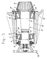
- Fig. 3 shows a section through a drive part of a differential drive having a bearing assembly according to the invention.
- Fig. 4 shows a fourth embodiment of a hub assembly.
- Fig. 5 shows a partial section through a bearing assembly for a railway vehicle.
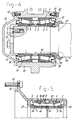
- Fig. 6 shows a bearing assembly with ABS mechanism.
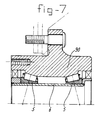
- Fig. 7 shows a fifth embodiment of a hub assembly.
- the hub assembly shown in Fig. 1 shows a bearing assembly 1 according to the invention.
- Said bearing assembly 1 is assembled from two tapered bearings 2, an outer bush 4 disposed on the outer races 3 of the tapered bearings 2, and also an inner bush 6 disposed in the inner races 5 of the tapered bearings 2.
- the outer bush 4 has an inward flanged region 7 (tubular section) which has stop faces on either side for the outer races 3 of the tapered bearings 2.
- a supporting ring 8 is welded by means of a laser weld 9 onto the inner bush 6 at one end, and the supporting ring 10 is welded by means of laser weld 11 onto said supporting ring at the other end.
- the desired axial initial tension is also applied to the tapered bearings 2.
- the supporting rings 8, 10 After the supporting rings 8, 10 have been fixed by the laser weld 9, 11, a bearing assembly 1 with the desired axial initial load is obtained as a result.
- the bearing assembly 1 can be sealed off by means of the seals 12, 13, which are known per se and are therefore not described in any further detail.
- the inner bush 6 is disposed on a fixed shaft 14'.
- the outer bush 4 is inserted into the hub 14, which has a flange 15 on which a wheel 16' and a brake drum/brake disc 16a are fixed by means of bolted connections 16.
- the outer bush 4 has a radially outward pointing flange 17.
- a drive shaft 18 which also has an outward pointing flange 19. Both flanges 17, 19 are fixed by means of bolts 20 to the hub 14.
- the inner bush 6 is pressed against the shoulder 22 of the fixed shaft 14' by means of a threaded ring 21, which is screwed onto the fixed shaft 14'.
- FIG. 2 shows a hub assembly with a bearing assembly 23, the outer bush 24 of which contains a supporting ring 25 which is fixed by means of pins 26 to the outer bush 24.
- the outer races 3 of the tapered bearings 2 rest under initial load against the faces of said supporting ring 25 which face away from each other.
- the inner bush indicated in its entirety by 27 consists of the inner bush halves 28, which are fixed to each other by means of friction weld 29. At their ends facing away from each other the inner bush halves 28 have a radially outward flanged region 30, against which the inner races 5 of the tapered bearings 2 rest.
- the shape of the supporting ring is selected in such a way that welding spatters are collected in an enclosed space, with the result that they cannot penetrate into the bearing.
- the outer bush 24 is again fixed to the hub by means of flange 17; the inner bush is held pressed against the shoulder 22 on the fixed shaft 14' by clamping ring 31, which is fixed in the fixed shaft 14' by means of bolts 32.
- the bearing itself can be simplified, for example by leaving out the small end flange of the inner race.
- a hub assembly shown in Fig. 3 shows a drive shaft - indicated in its entirety by 33 - of a differential drive which bears a bevel gear 34 at its one end. Said bevel gear 34 forms part of the bearing assembly. At its other end, the drive shaft 33 bears a coupling flange 36, to which a wheel can be fixed.
- the bearing assembly indicated in its entirety by 37 comprises, in addition to the drive shaft 33, an outer bush 38, two tapered bearings 2, and seals 40.
- the inner races 5 of the tapered bearings 2 are disposed on the drive shaft 33, and rest against shoulders 41 and 42.
- the outer races 3 of the tapered bearings 2 rest against the radially inward flanged parts 43, 44 of the outer bush 38.
- the drive shaft 33 consists of shaft parts 45, 46, which are fixed to each other by means of welding and/or screwed connection 47.
- the distances between shoulder 41, shoulder 42 and flanged regions 43, 44 are such that the desired axial initial load in the tapered bearings 2 is obtained when the shaft halves 45, 46 are connected to each other. Therefore, after the drive shaft 33 has been assembled, a weld 49 is made between the shaft parts 45 and 46 by means of a high-energy beam, for example a laser beam, through hole 48 in the outer bush 38.
- the outer bush 38 is fixed in the housing 50 of a differential housing.
- the exemplary embodiment shown in Fig. 4 relates to a hub assembly for a railway bearing.
- the bearing assembly indicated in its entirety by 52, is fixed on the shaft end 51 by means of clamping ring 53.
- Said clamping ring 53 is screwed into the shaft end 51 by means of bolts 54.
- the inner bush 56 being pressed by the clamping ring 53 rests against the shoulder 57.
- the design of the bearing assembly 52 largely corresponds to the bearing assembly 1 shown in Fig. 1. Only the radially outward pointing flange of the outer bush 4 is not present here.
- the desired sealing of the bearing assembly 52 is ensured by means of the seal 58.
- the outer bush 4 of the bearing assembly 52 is fixed in the bearing housing 59 by means of the cap 60 and the supporting ring 61.
- the latter are fixed to the opposite ends of the hub 59 by means of bolts 62, in such a way that the outer bush 4 can be retained in a confined manner between them.
- the bearing temperature can be monitored by means of temperature sensor 80. Said sensors 80 are connected to signal lines 81, which are connected to recording and/or warning elements (not shown).
- the bearing assembly for a lorry shown in Fig. 5, with flanges 82 and bolts 83 for the fitting of a wheel, brake drum and/or brake disc comprises an outer bush 63 and an inner bush formed from the halves 64, 65, which are fixed to each other by connecting ring 66.
- the inner bush halves have radially outward flanged edges 67, which fit into the groove 68 of fixing ring 66 and place the bearing assembly under initial tension.
- Both inner bush halves 64, 65 also have a radially outward flanged region 69, against which the inner races 5 of the tapered bearings 2 rest.
- the outer races 3 of said tapered bearings 2 are also supported against the supporting ring 70, which is fixed in the outer race 63 by means of headless pins or bolts 71 or by means of high-energy welding.
- an ABS sensor 87 is disposed on the fixed inner bush 88.
- the cable 85 connected to the ABS sensor 87 is guided out of the bearing assembly by way of groove 86 in the inner race.
- the embodiment of figure 7 shows a bearing unit having two outer races which together form an outer annulus 90.
- the inner races 5 are contained on an inner bush 6, as according to the embodiment of figure 1.
- the inner races may be carried out as a common inner annulus in which case the outer races are contained in an outer bush.
Landscapes
- Engineering & Computer Science (AREA)
- General Engineering & Computer Science (AREA)
- Mechanical Engineering (AREA)
- Rolling Contact Bearings (AREA)
- Support Of The Bearing (AREA)
Abstract
Bearing assembly for a vehicle hub, comprises two coaxial rolling bearings (2), whose inner races (5) and whose outer races are interconnected, which interconnected outer races (3) provided with means (7,14) for fixing a wheel thereto, or with means for fixing said outer bush to the suspension frame of a vehicle wheel.
The rolling bearings (2) can be supported on a central element (6) and the outer bush (4) under initial load in the axial direction.
Description
- The invention relates to the field of wheel bearings for vehicles, such as heavy road or cross-country vehicles, trailers and railway vehicles. In the case of such vehicles two coaxial bearings are used in the wheel hub. Types of bearings which can be placed under a certain initial load, such as tapered bearings, are often used for this purpose. However, other types of bearings are also used, for example a combination of a ball bearing and a roller bearing.
- When the vehicle axle is being assembled, these bearings must be fitted in their intended position on the axle and/or the suspension frame of the wheel. This operation must be carried out with the necessary care, since any damage or penetrating dirt can considerably shorten the service life of the bearings. However, the environment in which such operations are carried out is not always optimal, with the result that the necessary quality cannot be guaranteed. Besides, a degree of specialization is required - certainly if initial tension is used - which manufacturers do have, but which the vehicle producer or the maintenance workshop do not always have.
- There is therefore a need for a bearing which is more satisfactory in this respect.
- To this end, the invention relates to a bearing assembly for a vehicle hub, comprising two coaxial rolling bearings whose inner races and whose outer races are interconnected, which interconnected outer races are provided with means for fixing a wheel thereto, or with means for fixing said outer bush to the suspension frame of a vehicle wheel.
- The bearing assembly according to the invention forms a unit which can be fitted directly in its entirety on an axle and/or suspension frame of a vehicle. It is not necessary in this case to fit all components separately on the axle. Moreover, the bearing assembly can be provided with seals, with the result that it is impossible for dirt to penetrate and the lubricant is retained in the bearing assembly.
- The bearing assembly according to the invention can be carried out in various ways. According to a first variant, the outer races are accomodated in a common outer bush, which outer bush is provided with means for fixing a wheel thereto, or with means for fixing said outer bush to the suspension frame of a vehicle wheel. Moreover, also the inner races are accomodated on a common central element.
- The rolling bearings can be supported on the central element and the outer bush under initial load in the axial direction. This initial load is applied in advance when the bearing assembly is being assembled, so that these precision operations also need no longer be carried out when the assembly is being fitted on the axle. It is thus possible to guarantee the correct setting of the initial load.
- The stops required for applying and maintaining the initial load can be produced in various ways. According to a first possibility, the outer bush can have a radially inward flanged region whose parts facing away from each other in the axial direction form stop faces for the outer races of the rolling bearings.
- However, as an alternative, a supporting ring can also be provided in the outer bush, which supporting ring has stop faces for the outer races of the rolling bearings. Said supporting ring can be fixed in the outer bush by means of pins or bolts situated in holes provided radially in the supporting ring and in the outer bush. High-energy welding can also be used for the fixing. With a suitable choice of the materials for the supporting ring, the initial tension can also be retained when there is thermal expansion.
- The central element can be designed in various ways, depending on the use of the bearing assembly. For example, the inner races of the rolling bearings can be accommodated on an inner bush. Said inner bush can have at its opposite ends stops for each of the inner races of the rolling bearings, in order to keep the rolling bearings pressed under initial tension in the axial direction, and possibly in order to absorb and pass on axial forces.
- These stops can be formed by supporting rings provided at the opposite ends of the inner bush. These supporting rings are preferably welded onto the inner bush by means of a high-energy beam such as a laser beam. However, as an alternative, another connection method can be used, for example screw thread.
- Instead of separate supporting rings, the ends of the inner bush can have radially outward flanged regions whose parts facing each other in the axial direction form stop faces for the inner races of the rolling bearings.
- According to a further possibility, the inner bush consists of two inner bush halves, which at their ends facing away from each other are each flanged radially outwards. These inner bush halves are preferably welded to each other when the bearing assembly is being assembled, for example by friction welding or laser welding.
- As an alternative, the inner bush halves can have at their ends facing each other radially outward flanged regions, which regions engage in an inner peripheral groove of a fixing ring.
- The inner races of the rolling bearings can be accommodated on a shaft instead of on an inner bush. Said shaft can be a drive shaft which is rotatably supported by the bearings in a fixed housing such as that used in the case of differential drives in motor vehicles, as in the case of lorries.
- For purposes of manufacturing such a bearing assembly, the shaft can consist of two shaft parts which are fixed to each other at their ends facing each other, and at their ends facing away from each other bear stops for the inner races of the rolling bearings, for the purpose of keeping the rolling bearings pressed under axial initial tension.
- Said shaft parts can be fixed to each other by a screw connection; the shaft parts can also be fixed to each other by means of a high-energy beam, such as a laser beam, in which case a smooth centring shaft is used instead of a screw thread.
- The bearing assembly according to the invention furthermore can be carried out according to a second variant, in which the outer races form a common outer annulus. Moreover, the inner races may form a common inner annulus.
- The invention also relates to a hub assembly for a vehicle, comprising a bearing assembly of the type described above, in which the outer bush has a radially outward pointing flange which is fixed to the wheel hub, drum or disc brake.
- The flange can have holes, through which bolts run, the shank of which bolts is screwed in each case into a threaded axial hole in the wheel hub, drum or disc brake.
- The inner bush can be fixed to a shaft which has a shoulder against which the inner bush is clamped by means of a clamping ring disposed on the shaft. If said shaft is also provided, a drive shaft having a radially outward pointing flange which is fixed to the wheel hub by means of the bolts can run through it.
- The bearing assembly may or may not be completed by electrical/electronic control equipment, for determining the number of revolutions and/or the temperatures of the bearing races, for example ABS in motor vehicles and temperature determination for train bearings.
- A number of exemplary embodiments of a hub assembly having a bearing assembly according to the invention will be described in greater detail below with reference to the figures.
- Fig. 1 shows a section through a first hub assembly according to the invention.
- Fig. 2 shows a section through a second hub assembly.
- Fig. 3 shows a section through a drive part of a differential drive having a bearing assembly according to the invention.
- Fig. 4 shows a fourth embodiment of a hub assembly.
- Fig. 5 shows a partial section through a bearing assembly for a railway vehicle.
- Fig. 6 shows a bearing assembly with ABS mechanism.
- Fig. 7 shows a fifth embodiment of a hub assembly.
- The hub assembly shown in Fig. 1 shows a bearing assembly 1 according to the invention. Said bearing assembly 1 is assembled from two
tapered bearings 2, an outer bush 4 disposed on theouter races 3 of thetapered bearings 2, and also aninner bush 6 disposed in theinner races 5 of thetapered bearings 2. - The outer bush 4 has an inward flanged region 7 (tubular section) which has stop faces on either side for the
outer races 3 of thetapered bearings 2. A supporting ring 8 is welded by means of a laser weld 9 onto theinner bush 6 at one end, and the supportingring 10 is welded by means oflaser weld 11 onto said supporting ring at the other end. When the supportingrings 8, 10 are being fitted, the desired axial initial tension is also applied to thetapered bearings 2. After the supportingrings 8, 10 have been fixed by thelaser weld 9, 11, a bearing assembly 1 with the desired axial initial load is obtained as a result. - After the application of the lubricant, the bearing assembly 1 can be sealed off by means of the
seals 12, 13, which are known per se and are therefore not described in any further detail. - In the exemplary embodiment illustrated, the
inner bush 6 is disposed on a fixed shaft 14'. The outer bush 4 is inserted into thehub 14, which has aflange 15 on which a wheel 16' and a brake drum/brake disc 16a are fixed by means of boltedconnections 16. - The outer bush 4 has a radially outward pointing
flange 17. Running through the fixed shaft 14' is adrive shaft 18, which also has an outward pointingflange 19. Bothflanges bolts 20 to thehub 14. - The
inner bush 6 is pressed against theshoulder 22 of the fixed shaft 14' by means of a threadedring 21, which is screwed onto the fixed shaft 14'. - The example shown in Fig. 2 shows a hub assembly with a bearing
assembly 23, theouter bush 24 of which contains a supportingring 25 which is fixed by means ofpins 26 to theouter bush 24. Theouter races 3 of the taperedbearings 2 rest under initial load against the faces of said supportingring 25 which face away from each other. - The inner bush indicated in its entirety by 27 consists of the inner bush halves 28, which are fixed to each other by means of
friction weld 29. At their ends facing away from each other the inner bush halves 28 have a radially outwardflanged region 30, against which theinner races 5 of the taperedbearings 2 rest. The shape of the supporting ring is selected in such a way that welding spatters are collected in an enclosed space, with the result that they cannot penetrate into the bearing. - When the inner bush halves 28 are being welded together, the desired axial initial load can thus be applied in the
tapered bearings 2. - The
outer bush 24 is again fixed to the hub by means offlange 17; the inner bush is held pressed against theshoulder 22 on the fixed shaft 14' by clampingring 31, which is fixed in the fixed shaft 14' by means ofbolts 32. - Since the bearings will no longer be replaced, the bearing itself can be simplified, for example by leaving out the small end flange of the inner race.
- The exemplary embodiment of a hub assembly shown in Fig. 3 shows a drive shaft - indicated in its entirety by 33 - of a differential drive which bears a
bevel gear 34 at its one end. Saidbevel gear 34 forms part of the bearing assembly. At its other end, thedrive shaft 33 bears acoupling flange 36, to which a wheel can be fixed. - The bearing assembly indicated in its entirety by 37 comprises, in addition to the
drive shaft 33, anouter bush 38, twotapered bearings 2, and seals 40. - The
inner races 5 of the taperedbearings 2 are disposed on thedrive shaft 33, and rest againstshoulders 41 and 42. Theouter races 3 of the taperedbearings 2 rest against the radially inwardflanged parts outer bush 38. - The
drive shaft 33 consists ofshaft parts shoulder 42 andflanged regions tapered bearings 2 is obtained when the shaft halves 45, 46 are connected to each other. Therefore, after thedrive shaft 33 has been assembled, aweld 49 is made between theshaft parts hole 48 in theouter bush 38. - The
outer bush 38 is fixed in thehousing 50 of a differential housing. - The exemplary embodiment shown in Fig. 4 relates to a hub assembly for a railway bearing. The bearing assembly, indicated in its entirety by 52, is fixed on the
shaft end 51 by means of clampingring 53. Said clampingring 53 is screwed into theshaft end 51 by means of bolts 54. By means of supportingring 55, theinner bush 56 being pressed by the clampingring 53 rests against theshoulder 57. For the rest, the design of the bearingassembly 52 largely corresponds to the bearing assembly 1 shown in Fig. 1. Only the radially outward pointing flange of the outer bush 4 is not present here. The desired sealing of the bearingassembly 52 is ensured by means of theseal 58. - The outer bush 4 of the bearing
assembly 52 is fixed in the bearinghousing 59 by means of thecap 60 and the supportingring 61. The latter are fixed to the opposite ends of thehub 59 by means ofbolts 62, in such a way that the outer bush 4 can be retained in a confined manner between them. The bearing temperature can be monitored by means of temperature sensor 80. Said sensors 80 are connected to signal lines 81, which are connected to recording and/or warning elements (not shown). - The bearing assembly for a lorry shown in Fig. 5, with
flanges 82 andbolts 83 for the fitting of a wheel, brake drum and/or brake disc, comprises an outer bush 63 and an inner bush formed from thehalves 64, 65, which are fixed to each other by connectingring 66. The inner bush halves have radially outwardflanged edges 67, which fit into the groove 68 of fixingring 66 and place the bearing assembly under initial tension. Both inner bush halves 64, 65 also have a radially outwardflanged region 69, against which theinner races 5 of the taperedbearings 2 rest. - The
outer races 3 of saidtapered bearings 2 are also supported against the supporting ring 70, which is fixed in the outer race 63 by means of headless pins or bolts 71 or by means of high-energy welding. - In the bearing assembly shown in Figure 6, an
ABS sensor 87 is disposed on the fixedinner bush 88. A counter-ring 84, bearing the usual ribs which can be detected by theABS sensor 87, is disposed in the rotaryouter bush 89. Thecable 85 connected to theABS sensor 87 is guided out of the bearing assembly by way ofgroove 86 in the inner race. - The embodiment of figure 7 shows a bearing unit having two outer races which together form an
outer annulus 90. Theinner races 5 are contained on aninner bush 6, as according to the embodiment of figure 1. - Alternatively, the inner races may be carried out as a common inner annulus in which case the outer races are contained in an outer bush.
Claims (30)
- Bearing assembly for a vehicle hub, comprising two coaxial rolling bearings (2), whose inner races (5) and whose outer races are interconnected, which interconnected outer races (3) are provided with means (7, 14) for fixing a wheel thereto, or with means for fixing said outer bush to the suspension frame of a vehicle wheel.
- Bearing assembly according to Claim 1, in which the outer races (3) are accomodated in a common outer bush (4; 24; 38; 63), which outer bush is provided with means (17, 14) for fixing a wheel thereto, or with means for fixing said outer bush to the suspension frame (50) of a vehicle wheel.
- Bearing assembly according to Claim 1 or 2, in which the inner races (5) are accomodated on a common central element (6; 27; 33; 56; 64; 65; 66).
- Bearing assembly according to Claim 2 and 3, in which the rolling bearings (2) are supported on the central element (6; 27; 33; 56; 64, 65, 66) and the outer bush (4; 24; 38; 63) under initial load in the axial direction.
- Bearing assembly according to Claim 4, in which the outer bush (4; 24; 38; 63) has a stop (7; 25; 44, 43; 63) for each of the outer races (3) of the rolling bearings (2), for keeping the rolling bearings (2) pressed in the axial direction under initial load.
- Bearing assembly according to Claim 5, in which the outer bush (4) has a radially inward flanged region (7) whose parts facing away from each other in the axial direction form stop faces for the outer races (3) of the rolling bearings (2).
- Bearing assembly according to Claim 5, in which a supporting ring (25) is provided in the outer bush (24), which supporting ring has stop faces for the outer races (3) of the rolling bearings (2).
- Bearing assembly according to Claim 7, in which the supporting ring (25) is fixed in the outer bush (24) by means of pins or bolts (26) situated in holes provided radially in the supporting ring (25) and in the outer bush (24).
- Bearing assembly according to one of the preceding claims, in which the inner races (5) of the rolling bearings (2) are accommodated on an inner bush (6; 27; 56; 64; 65, 66).
- Bearing assembly according to Claim 9, in which the inner bush (6; 27; 56; 64, 65, 66) has at its opposite ends stops (8, 10; 30; 41; 42; 68, 69) for each of the inner races (5) of the rolling bearings (2), in order to keep the rolling bearings (2) pressed under initial tension in the axial direction.
- Bearing assembly according to Claim 10, in which the inner bush (6) has supporting rings (8, 10) at its opposite ends.
- Bearing assembly according to Claim 11, in which the supporting rings (8, 10) are welded onto the inner bush (6) by means of a high-energy beam such as a laser beam.
- Bearing assembly according to Claim 10, in which the ends of the inner bush (27; 64, 65, 66) have radially outward flanged regions (30; 68, 69) whose parts facing each other in the axial direction form stop faces for the inner races (3) of the rolling bearings (2).
- Bearing assembly according to Claim 13, in which the inner bush (27; 64, 65, 66) consists of two inner bush halves (28; 64; 65), which at their ends facing away from each other are flanged radially outwards.
- Bearing assembly according to Claim 14, in which the inner bush halves (28) are fixed to each other by welds (29).
- Bearing assembly according to Claim 14, in which the inner bush halves (64, 65) have at their ends facing each other radially outward flanged regions (67), which regions engage in an inner peripheral groove (68) of a fixing ring (66).
- Bearing assembly according to one of Claims 3 - 8, in which the inner races (5) of the rolling bearings (2) are accommodated on a shaft (33).
- Bearing assembly according to Claim 17, in which the shaft (33) consists of two shaft parts (45, 46) which are fixed to each other at their ends facing each other, and at their ends facing away from each other bear stops (42, 43) for the inner races (5) of the rolling bearings, for the purpose of keeping the rolling bearings (2) pressed under axial initial tension.
- Bearing assembly according to Claim 18, in which the shaft parts (45, 46) are fixed to each other by a screwed connection (47).
- Bearing assembly according to Claim 19, in which the shaft parts (45, 46) are fixed (49) to each other by means of a high-energy beam, such as a laser beam.
- Bearing assembly according to one of the preceding claims, in which at least one seal (13; 40; 58) is provided between the outer bush (4; 24; 38; 63) and/or an outer race interacting therewith, on the one hand, and the central element (6; 27; 33; 56; 64, 65, 66) and/or an inner race interacting therewith, on the other hand.
- Bearing assembly according to Claim 21, in which a seal is provided at both ends of the bearing assembly.
- Bearing assembly according to Claim 1, or 1 and any of Claims 9 - 22, in which the outer races form a common outer annulus.
- Bearing assembly according to any of Claims 1 - 6 or 23, in which the inner races form a common inner annulus.
- Hub assembly for a vehicle, comprising a bearing assembly according to one of the preceding claims, in which the outer bush (4; 24) or outer annulus (90) has a radially outward pointing flange (17) for fixing thereto the wheel hub (14) of a wheel and/or brake drum/brake disc.
- Hub assembly according to Claim 25, in which the flange (17) is provided with holes, through which holes bolts (20) run, the shank of which bolts in each case is screwed into a threaded axial hole in the wheel hub (14).
- Hub assembly according to Claim 26, in which the inner bush (6; 28; 56) or inner annulus is fixed on a shaft (14'), which shaft (14') has a shoulder (13', 22) against which the inner bush (6; 28) is clamped by means of a clamping ring (21; 31) disposed on the shaft.
- Hub assembly according to Claim 27, in which the shaft (14') is hollow, through which hollow shaft (14') a drive shaft (18) runs, which drive shaft has a radially outward pointing flange (19) which is fixed to the wheel hub (14) by means of the bolts (20).
- Hub assembly according to Claims 25, 26, 27 or 28, in which an ABS sensor and/or temperature sensor is provided.
- Hub assembly according to Claim 29, in which a groove is provided in the parts of the bearing assembly fixed to the suspension frame, for the accommodation of signal cables.
Applications Claiming Priority (2)
| Application Number | Priority Date | Filing Date | Title |
|---|---|---|---|
| NL9400971 | 1994-06-14 | ||
| NL9400971A NL9400971A (en) | 1994-06-14 | 1994-06-14 | Vehicle hub bearing assembly as well as hub assembly. |
Publications (1)
| Publication Number | Publication Date |
|---|---|
| EP0687826A1 true EP0687826A1 (en) | 1995-12-20 |
Family
ID=19864313
Family Applications (1)
| Application Number | Title | Priority Date | Filing Date |
|---|---|---|---|
| EP95201533A Withdrawn EP0687826A1 (en) | 1994-06-14 | 1995-06-09 | Bearing assembly for avehicle hub, and also hub assembly |
Country Status (6)
| Country | Link |
|---|---|
| US (1) | US5667313A (en) |
| EP (1) | EP0687826A1 (en) |
| JP (1) | JPH0848107A (en) |
| KR (1) | KR960001525A (en) |
| NL (1) | NL9400971A (en) |
| PL (1) | PL309096A1 (en) |
Cited By (20)
| Publication number | Priority date | Publication date | Assignee | Title |
|---|---|---|---|---|
| EP0800011A3 (en) * | 1996-03-26 | 1998-07-08 | SKF INDUSTRIE S.p.A. | Protective element against electrolytic corrosion, particularly for the strut of a vehicle and its bearing |
| NL1006545C2 (en) * | 1997-07-10 | 1999-01-12 | Skf Ind Trading & Dev | Glued bearing unit for truck. |
| DE19918351A1 (en) * | 1999-04-22 | 2000-10-26 | Volkswagen Ag | Bearing unit, in particular wheel bearing unit for motor vehicles |
| WO2001063134A1 (en) * | 2000-02-24 | 2001-08-30 | Rad-Sport-Arnold Gmbh | Roller bearing joint |
| WO2006018132A1 (en) * | 2004-08-10 | 2006-02-23 | Schaeffler Kg | Multi-row angular ball bearing |
| WO2006092256A1 (en) * | 2005-03-03 | 2006-09-08 | Ab Skf | Bearing arrangement |
| DE102006025274A1 (en) * | 2006-05-31 | 2007-12-06 | Daimlerchrysler Ag | Hub bearing unit for commercial motor vehicle, has outer ring attached into recess of hub ring, and stop unit of outer partial rings and elevation of recess of hub ring arranged opposite to each other |
| EP1870606A1 (en) * | 2006-06-13 | 2007-12-26 | Hansen Transmissions International Nv | Bearing and method whereby such a bearing can be applied |
| US7413261B2 (en) | 2002-02-20 | 2008-08-19 | Meritor Heavy Vehicle Systems Cameri Spa | Wheel hub assembly |
| WO2009062467A1 (en) * | 2007-11-17 | 2009-05-22 | Schaeffler Kg | Wheel carrier assembly and method for mounting it |
| DE102008039477A1 (en) | 2008-08-23 | 2010-02-25 | Schaeffler Kg | Pinion shaft arrangement for use in vehicle gearbox for transmitting drive torque, has bearing surface pre-formed at pinion head and/or connection flange to connect shaft with another shaft and/or shaft nut for pre-tensioning of arrangement |
| WO2012116905A1 (en) | 2011-03-01 | 2012-09-07 | Saf-Holland Gmbh | Axle system |
| DE102011075317A1 (en) | 2011-05-05 | 2012-11-08 | Schaeffler Technologies AG & Co. KG | Taper roller bearing for use on pinion shaft for differential gear of vehicle for transferring radial and axial forces, has outer ring held at truncated cone-shaped rolling bodies by flanged sleeve and forming unit with inner ring |
| CN104175800A (en) * | 2014-08-20 | 2014-12-03 | 山东浩信机械有限公司 | Integral hub |
| DE102014215073A1 (en) * | 2014-07-31 | 2016-02-04 | Aktiebolaget Skf | Adapter and bearing unit and wheel bearing with the adapter |
| FR3029992A1 (en) * | 2014-12-12 | 2016-06-17 | Ntn-Snr Roulements | BEARING BEARING |
| DE102011004897B4 (en) * | 2011-03-01 | 2017-07-13 | Saf-Holland Gmbh | axle system |
| EP3287652A1 (en) * | 2016-08-24 | 2018-02-28 | Safran Landing Systems | Aircraft wheel with a separable bearing box |
| FR3073558A1 (en) * | 2017-11-10 | 2019-05-17 | Safran Aircraft Engines | BEARING BLOCK EQUIPPED FOR TURBOMACHINE |
| WO2019195746A1 (en) * | 2018-04-05 | 2019-10-10 | The Timken Company | Self retained multi-row bearing unit and installing method |
Families Citing this family (28)
| Publication number | Priority date | Publication date | Assignee | Title |
|---|---|---|---|---|
| US6035507A (en) * | 1997-02-13 | 2000-03-14 | Kelsey-Hayes Company | Method for coordinating a rotor and hub |
| DE19913200B4 (en) * | 1999-03-24 | 2005-07-28 | Ina-Schaeffler Kg | Bearing arrangement for a screw drive |
| FR2806763B1 (en) * | 2000-03-21 | 2002-08-16 | Sagem | DOUBLE BALL BEARING COMPOSITE BEARING, METHOD FOR MOUNTING THE SAME, AND TOOL FOR MAKING A PAIR OF RINGS THEREOF |
| US6759963B2 (en) * | 2001-05-08 | 2004-07-06 | Meritor Heavy Vehicle Technology, Llc | Wheel bearing temperature indicator |
| US20020181325A1 (en) * | 2001-06-05 | 2002-12-05 | Engel David J | Mixer seal and bearing apparatus and method |
| GB0116878D0 (en) * | 2001-07-11 | 2001-09-05 | Timestrip Ltd | Time indicator |
| US20030070501A1 (en) * | 2001-10-17 | 2003-04-17 | Bell Dale K. | Axle lubricant isolation |
| US20030108262A1 (en) * | 2001-12-10 | 2003-06-12 | Bell Dale K. | Lightweight bearing cage |
| US6715913B2 (en) * | 2002-03-29 | 2004-04-06 | Spx Corporation | Shaft bearing support method and apparatus |
| US6776261B2 (en) | 2002-05-29 | 2004-08-17 | Garlock Sealing Technologies Llc | Lubricant monitoring system |
| DE102004035073A1 (en) * | 2004-07-20 | 2006-03-16 | Zf Friedrichshafen Ag | bearing arrangement |
| JP2008215374A (en) * | 2007-02-28 | 2008-09-18 | Ntn Corp | Bearing device for railroad vehicle axle |
| DE102008009283B4 (en) * | 2008-02-15 | 2021-07-29 | Schaeffler Technologies AG & Co. KG | Wheel bearing device for a motor vehicle |
| FI122663B (en) * | 2009-02-10 | 2012-05-15 | Kone Corp | Procedure for mounting double bearings in a casting piece and wheels comprising a double bearing |
| DE102010033823A1 (en) * | 2010-08-09 | 2011-02-24 | Schaeffler Technologies Gmbh & Co. Kg | Wheel bearing unit for utility vehicles, has two taper roller bearings with inner rings and outer rings, and connection of inner rings is formed by connecting unit |
| US20120082407A1 (en) * | 2010-10-01 | 2012-04-05 | Amsted Rail Company, Inc. | Railway car bearing seal spacer assembly |
| ITTO20111181A1 (en) * | 2011-12-21 | 2013-06-22 | Gate Srl | ASSEMBLY PROCEDURE OF A TREE IN A CARRIER ELEMENT |
| CN102691729A (en) * | 2012-06-01 | 2012-09-26 | 青岛阿迪尔车桥制造有限公司 | Novel hub bearing component |
| US20130343686A1 (en) * | 2012-06-25 | 2013-12-26 | Leroy Edwards, JR. | Low Resistance Wheel |
| CN104685244A (en) * | 2012-10-10 | 2015-06-03 | Skf公司 | Rolling bearing comprising a housing having two parts and method for manufacturing and installing such a bearing |
| DE102012221399A1 (en) * | 2012-11-22 | 2014-05-22 | Aktiebolaget Skf | Bearing support unit for motor vehicle device, has sealing unit and sensor element that is fixed to outer ring or at bearing support element and is provided to measure rotational speed, with which inner ring rotates relative to outer ring |
| DE102012221400A1 (en) * | 2012-11-22 | 2014-06-05 | Aktiebolaget Skf | Bearing support device for motor vehicle device, has bearing and bearing support element, which is partially thin walled, where bearing support element is partially made from plastic and partially from sheet metal |
| EP3132947B1 (en) * | 2014-04-12 | 2018-05-09 | Shandong Haoxin Machinery Co. Ltd. | Wheel hub unit |
| DE102016211435A1 (en) * | 2016-06-27 | 2017-12-28 | Aktiebolaget Skf | Bearing unit and spacer |
| US10598227B2 (en) * | 2016-12-13 | 2020-03-24 | Aktiebolaget Skf | Installation unit and method for installing a bearing unit |
| KR102109341B1 (en) * | 2018-09-21 | 2020-05-12 | 주식회사 만도 | Electric Power Steering Apparatus for Vehicle |
| US11162529B2 (en) * | 2020-01-10 | 2021-11-02 | Sandcraft, Llc | Double row tapered bearing with press fit preloading elements |
| JPWO2023053386A1 (en) * | 2021-09-30 | 2023-04-06 |
Citations (16)
| Publication number | Priority date | Publication date | Assignee | Title |
|---|---|---|---|---|
| GB191006988A (en) * | 1910-03-21 | 1910-07-07 | Electric And Ordnance Accesori | Improvements relating to Roller Bearings. |
| US1420497A (en) * | 1921-04-20 | 1922-06-20 | Victor W Page | Pinion-shaft housing |
| FR543010A (en) * | 1920-11-25 | 1922-08-25 | Improvements to axles of road motor vehicles | |
| FR547858A (en) * | 1921-06-24 | 1922-12-27 | Usines De Roulements A Billes | Bearing for vehicle axles |
| DE838237C (en) * | 1950-10-15 | 1952-05-05 | Star Kugelhalter Ges M B H Deu | Hub-shaped roller bearing arrangement |
| FR1054128A (en) * | 1950-11-30 | 1954-02-08 | Ver Kugellagerfabriken A G Sch | Tensioner |
| FR2103756A5 (en) * | 1970-07-28 | 1972-04-14 | Willow Hill Ind Inc | |
| GB1392714A (en) * | 1971-04-05 | 1975-04-30 | Flexello Castors Wheels Ltd | Castor |
| WO1981001817A1 (en) * | 1979-12-21 | 1981-07-09 | Dana Corp | Axle drive assembly |
| GB2112500A (en) * | 1981-12-28 | 1983-07-20 | Dana Corp | Wheel assembly |
| EP0126607A2 (en) * | 1983-05-19 | 1984-11-28 | Federal-Mogul Corporation | Cartridge bearing apparatus and method |
| FR2556286A1 (en) * | 1983-12-08 | 1985-06-14 | Glaenzer Spicer Sa | Motor vehicle drive wheel hub assembly |
| FR2592107A1 (en) * | 1985-12-19 | 1987-06-26 | Skf Gmbh | SEALED BEARING IN PARTICULAR FOR ROLLER STACK |
| FR2595602A1 (en) * | 1986-03-13 | 1987-09-18 | Kugelfischer G Schaefer & Co | METHOD FOR WELDING THE PARTS OF A WHEEL SUPPORT |
| EP0317423A1 (en) * | 1987-11-16 | 1989-05-24 | Skf France | Hub assembly of a non-driven vehicle wheel equipped with a transmitter, and receiver for measuring the angular velocity of the wheel |
| US5328275A (en) * | 1993-05-06 | 1994-07-12 | Stemco Inc. | Unitized wheel hub and bearing assembly |
Family Cites Families (5)
| Publication number | Priority date | Publication date | Assignee | Title |
|---|---|---|---|---|
| US1399959A (en) * | 1920-01-16 | 1921-12-13 | Bengt M W Hanson | Ball-bearing |
| US1375112A (en) * | 1920-10-19 | 1921-04-19 | Fafnir Bearing Co | Ball-bearing |
| FR1049681A (en) * | 1951-01-20 | 1953-12-31 | Star Kugelhalter Gmbh Dt | Ball Bearing Device |
| US3425760A (en) * | 1966-07-20 | 1969-02-04 | Transport Eng Inc | Wheel assembly |
| US3986754A (en) * | 1975-08-18 | 1976-10-19 | The Torrington Company | Bearing with axial fit-up ring |
-
1994
- 1994-06-14 NL NL9400971A patent/NL9400971A/en not_active Application Discontinuation
-
1995
- 1995-06-09 EP EP95201533A patent/EP0687826A1/en not_active Withdrawn
- 1995-06-14 KR KR1019950015658A patent/KR960001525A/en not_active Ceased
- 1995-06-14 US US08/490,179 patent/US5667313A/en not_active Expired - Fee Related
- 1995-06-14 JP JP7170444A patent/JPH0848107A/en active Pending
- 1995-06-14 PL PL95309096A patent/PL309096A1/en unknown
Patent Citations (16)
| Publication number | Priority date | Publication date | Assignee | Title |
|---|---|---|---|---|
| GB191006988A (en) * | 1910-03-21 | 1910-07-07 | Electric And Ordnance Accesori | Improvements relating to Roller Bearings. |
| FR543010A (en) * | 1920-11-25 | 1922-08-25 | Improvements to axles of road motor vehicles | |
| US1420497A (en) * | 1921-04-20 | 1922-06-20 | Victor W Page | Pinion-shaft housing |
| FR547858A (en) * | 1921-06-24 | 1922-12-27 | Usines De Roulements A Billes | Bearing for vehicle axles |
| DE838237C (en) * | 1950-10-15 | 1952-05-05 | Star Kugelhalter Ges M B H Deu | Hub-shaped roller bearing arrangement |
| FR1054128A (en) * | 1950-11-30 | 1954-02-08 | Ver Kugellagerfabriken A G Sch | Tensioner |
| FR2103756A5 (en) * | 1970-07-28 | 1972-04-14 | Willow Hill Ind Inc | |
| GB1392714A (en) * | 1971-04-05 | 1975-04-30 | Flexello Castors Wheels Ltd | Castor |
| WO1981001817A1 (en) * | 1979-12-21 | 1981-07-09 | Dana Corp | Axle drive assembly |
| GB2112500A (en) * | 1981-12-28 | 1983-07-20 | Dana Corp | Wheel assembly |
| EP0126607A2 (en) * | 1983-05-19 | 1984-11-28 | Federal-Mogul Corporation | Cartridge bearing apparatus and method |
| FR2556286A1 (en) * | 1983-12-08 | 1985-06-14 | Glaenzer Spicer Sa | Motor vehicle drive wheel hub assembly |
| FR2592107A1 (en) * | 1985-12-19 | 1987-06-26 | Skf Gmbh | SEALED BEARING IN PARTICULAR FOR ROLLER STACK |
| FR2595602A1 (en) * | 1986-03-13 | 1987-09-18 | Kugelfischer G Schaefer & Co | METHOD FOR WELDING THE PARTS OF A WHEEL SUPPORT |
| EP0317423A1 (en) * | 1987-11-16 | 1989-05-24 | Skf France | Hub assembly of a non-driven vehicle wheel equipped with a transmitter, and receiver for measuring the angular velocity of the wheel |
| US5328275A (en) * | 1993-05-06 | 1994-07-12 | Stemco Inc. | Unitized wheel hub and bearing assembly |
Cited By (29)
| Publication number | Priority date | Publication date | Assignee | Title |
|---|---|---|---|---|
| EP0800011A3 (en) * | 1996-03-26 | 1998-07-08 | SKF INDUSTRIE S.p.A. | Protective element against electrolytic corrosion, particularly for the strut of a vehicle and its bearing |
| NL1006545C2 (en) * | 1997-07-10 | 1999-01-12 | Skf Ind Trading & Dev | Glued bearing unit for truck. |
| WO1999002875A1 (en) * | 1997-07-10 | 1999-01-21 | Skf Engineering & Research Centre B.V. | Bearing assembly for a vehicle hub |
| US6315457B1 (en) | 1997-07-10 | 2001-11-13 | Skf Engineering And Research Centre B.V. | Bearing assembly for a vehicle hub |
| DE19918351A1 (en) * | 1999-04-22 | 2000-10-26 | Volkswagen Ag | Bearing unit, in particular wheel bearing unit for motor vehicles |
| WO2001063134A1 (en) * | 2000-02-24 | 2001-08-30 | Rad-Sport-Arnold Gmbh | Roller bearing joint |
| US7413261B2 (en) | 2002-02-20 | 2008-08-19 | Meritor Heavy Vehicle Systems Cameri Spa | Wheel hub assembly |
| US8382213B2 (en) | 2002-02-20 | 2013-02-26 | Meritor Heavy Vehicle Systems Cameri Spa | Wheel hub assembly |
| WO2006018132A1 (en) * | 2004-08-10 | 2006-02-23 | Schaeffler Kg | Multi-row angular ball bearing |
| WO2006092256A1 (en) * | 2005-03-03 | 2006-09-08 | Ab Skf | Bearing arrangement |
| DE102006025274A1 (en) * | 2006-05-31 | 2007-12-06 | Daimlerchrysler Ag | Hub bearing unit for commercial motor vehicle, has outer ring attached into recess of hub ring, and stop unit of outer partial rings and elevation of recess of hub ring arranged opposite to each other |
| EP1870606A1 (en) * | 2006-06-13 | 2007-12-26 | Hansen Transmissions International Nv | Bearing and method whereby such a bearing can be applied |
| WO2009062467A1 (en) * | 2007-11-17 | 2009-05-22 | Schaeffler Kg | Wheel carrier assembly and method for mounting it |
| DE102008039477A1 (en) | 2008-08-23 | 2010-02-25 | Schaeffler Kg | Pinion shaft arrangement for use in vehicle gearbox for transmitting drive torque, has bearing surface pre-formed at pinion head and/or connection flange to connect shaft with another shaft and/or shaft nut for pre-tensioning of arrangement |
| WO2012116905A1 (en) | 2011-03-01 | 2012-09-07 | Saf-Holland Gmbh | Axle system |
| DE102011004897B4 (en) * | 2011-03-01 | 2017-07-13 | Saf-Holland Gmbh | axle system |
| DE102011075317A1 (en) | 2011-05-05 | 2012-11-08 | Schaeffler Technologies AG & Co. KG | Taper roller bearing for use on pinion shaft for differential gear of vehicle for transferring radial and axial forces, has outer ring held at truncated cone-shaped rolling bodies by flanged sleeve and forming unit with inner ring |
| DE102014215073A1 (en) * | 2014-07-31 | 2016-02-04 | Aktiebolaget Skf | Adapter and bearing unit and wheel bearing with the adapter |
| DE102014215073B4 (en) | 2014-07-31 | 2021-10-14 | Aktiebolaget Skf | Adapter as well as bearing unit and wheel bearing with the adapter |
| CN104175800A (en) * | 2014-08-20 | 2014-12-03 | 山东浩信机械有限公司 | Integral hub |
| CN104175800B (en) * | 2014-08-20 | 2017-11-03 | 山东浩信机械有限公司 | Integrated hub |
| FR3029992A1 (en) * | 2014-12-12 | 2016-06-17 | Ntn-Snr Roulements | BEARING BEARING |
| EP3287652A1 (en) * | 2016-08-24 | 2018-02-28 | Safran Landing Systems | Aircraft wheel with a separable bearing box |
| FR3055379A1 (en) * | 2016-08-24 | 2018-03-02 | Safran Landing Systems | AIRCRAFT WHEEL WITH SEPARABLE BEARING HOUSING |
| CN107776876A (en) * | 2016-08-24 | 2018-03-09 | 赛峰起落架系统公司 | Aircraft wheel equipped with separable bearing case |
| US10829208B2 (en) | 2016-08-24 | 2020-11-10 | Safran Landing Systems | Aircraft wheel with a separable bearing box |
| CN107776876B (en) * | 2016-08-24 | 2021-03-12 | 赛峰起落架系统公司 | Aircraft wheel equipped with separable bearing housing |
| FR3073558A1 (en) * | 2017-11-10 | 2019-05-17 | Safran Aircraft Engines | BEARING BLOCK EQUIPPED FOR TURBOMACHINE |
| WO2019195746A1 (en) * | 2018-04-05 | 2019-10-10 | The Timken Company | Self retained multi-row bearing unit and installing method |
Also Published As
| Publication number | Publication date |
|---|---|
| PL309096A1 (en) | 1995-12-27 |
| JPH0848107A (en) | 1996-02-20 |
| NL9400971A (en) | 1996-01-02 |
| KR960001525A (en) | 1996-01-25 |
| US5667313A (en) | 1997-09-16 |
Similar Documents
| Publication | Publication Date | Title |
|---|---|---|
| US5667313A (en) | Bearing assembly for a vehicle hub | |
| US5494358A (en) | Package bearing | |
| US5590967A (en) | Bearing unit for a vehicle wheel | |
| KR100208056B1 (en) | Sensor system and its mounting method | |
| KR100486471B1 (en) | Wheel mounting with a bearing race embedded in a cast component | |
| EP0864868A1 (en) | Single row tapered roller bearing | |
| CN108058540B (en) | Wheel end assembly with seal connected with adjusting ring interface | |
| US20040076356A1 (en) | Method for assembling a double row angular contact rolling element bearing unit, and bearing unit manufactured according to said method | |
| US20150137585A1 (en) | Bearing structure | |
| KR20030036763A (en) | Bearing unitized for handling | |
| KR20010033245A (en) | Angular contact bearing unit with one piece inner bearing element | |
| US6960024B2 (en) | Center bearing assembly including a support member containing a rheological fluid | |
| WO2011124501A1 (en) | Measuring system for rolling bearings | |
| US5281005A (en) | Spindle retainer for axle housing | |
| CN108791483B (en) | Wheel end assembly with deflector | |
| CN113874232A (en) | Steering knuckles for commercial vehicles, axle assemblies and axles for commercial vehicles | |
| JP2003262220A (en) | Structure provided with bearing device with sensor, and method of detecting abnormality of bearing device with sensor in structure | |
| CN101649860B (en) | Tapered roller drive wheel hub bearing unit | |
| WO1995013198A1 (en) | Wheel bearing arrangements | |
| NL1024411C2 (en) | Bearing unit for a vehicle hub with concentric hub sections. | |
| US20040010916A1 (en) | Method of making a wheel end assembly with a machined hub having reduced on-vehicle runout | |
| WO2002102607A1 (en) | Hub bearing unit with a separate axle stub | |
| US20180281513A1 (en) | Wheel end sensor mounting assembly for heavy-duty vehicles | |
| JP2005331025A (en) | Bearing with sensor | |
| US3270583A (en) | Axle housing assembly |
Legal Events
| Date | Code | Title | Description |
|---|---|---|---|
| PUAI | Public reference made under article 153(3) epc to a published international application that has entered the european phase |
Free format text: ORIGINAL CODE: 0009012 |
|
| AK | Designated contracting states |
Kind code of ref document: A1 Designated state(s): DE FR GB IT SE |
|
| 17P | Request for examination filed |
Effective date: 19951122 |
|
| 17Q | First examination report despatched |
Effective date: 19970610 |
|
| RAP1 | Party data changed (applicant data changed or rights of an application transferred) |
Owner name: SKF ENGINEERING AND RESEARCH CENTRE B.V. |
|
| RAP1 | Party data changed (applicant data changed or rights of an application transferred) |
Owner name: SKF ENGINEERING & RESEARCH CENTRE B.V. |
|
| STAA | Information on the status of an ep patent application or granted ep patent |
Free format text: STATUS: THE APPLICATION IS DEEMED TO BE WITHDRAWN |
|
| 18D | Application deemed to be withdrawn |
Effective date: 20000331 |