EP0691704B1 - Verbinderhalter mit räumlicher Einstellung der Lage des Verbinders - Google Patents
Verbinderhalter mit räumlicher Einstellung der Lage des Verbinders Download PDFInfo
- Publication number
- EP0691704B1 EP0691704B1 EP94830339A EP94830339A EP0691704B1 EP 0691704 B1 EP0691704 B1 EP 0691704B1 EP 94830339 A EP94830339 A EP 94830339A EP 94830339 A EP94830339 A EP 94830339A EP 0691704 B1 EP0691704 B1 EP 0691704B1
- Authority
- EP
- European Patent Office
- Prior art keywords
- connector
- plate
- plates
- holder
- supporting element
- Prior art date
- Legal status (The legal status is an assumption and is not a legal conclusion. Google has not performed a legal analysis and makes no representation as to the accuracy of the status listed.)
- Expired - Lifetime
Links
Images


Classifications
-
- H—ELECTRICITY
- H01—ELECTRIC ELEMENTS
- H01R—ELECTRICALLY-CONDUCTIVE CONNECTIONS; STRUCTURAL ASSOCIATIONS OF A PLURALITY OF MUTUALLY-INSULATED ELECTRICAL CONNECTING ELEMENTS; COUPLING DEVICES; CURRENT COLLECTORS
- H01R12/00—Structural associations of a plurality of mutually-insulated electrical connecting elements, specially adapted for printed circuits, e.g. printed circuit boards [PCB], flat or ribbon cables, or like generally planar structures, e.g. terminal strips, terminal blocks; Coupling devices specially adapted for printed circuits, flat or ribbon cables, or like generally planar structures; Terminals specially adapted for contact with, or insertion into, printed circuits, flat or ribbon cables, or like generally planar structures
- H01R12/70—Coupling devices
- H01R12/77—Coupling devices for flexible printed circuits, flat or ribbon cables or like structures
- H01R12/79—Coupling devices for flexible printed circuits, flat or ribbon cables or like structures connecting to rigid printed circuits or like structures
-
- H—ELECTRICITY
- H01—ELECTRIC ELEMENTS
- H01R—ELECTRICALLY-CONDUCTIVE CONNECTIONS; STRUCTURAL ASSOCIATIONS OF A PLURALITY OF MUTUALLY-INSULATED ELECTRICAL CONNECTING ELEMENTS; COUPLING DEVICES; CURRENT COLLECTORS
- H01R13/00—Details of coupling devices of the kinds covered by groups H01R12/70 or H01R24/00 - H01R33/00
- H01R13/62—Means for facilitating engagement or disengagement of coupling parts or for holding them in engagement
- H01R13/629—Additional means for facilitating engagement or disengagement of coupling parts, e.g. aligning or guiding means, levers, gas pressure electrical locking indicators, manufacturing tolerances
- H01R13/631—Additional means for facilitating engagement or disengagement of coupling parts, e.g. aligning or guiding means, levers, gas pressure electrical locking indicators, manufacturing tolerances for engagement only
- H01R13/6315—Additional means for facilitating engagement or disengagement of coupling parts, e.g. aligning or guiding means, levers, gas pressure electrical locking indicators, manufacturing tolerances for engagement only allowing relative movement between coupling parts, e.g. floating connection
-
- H—ELECTRICITY
- H05—ELECTRIC TECHNIQUES NOT OTHERWISE PROVIDED FOR
- H05K—PRINTED CIRCUITS; CASINGS OR CONSTRUCTIONAL DETAILS OF ELECTRIC APPARATUS; MANUFACTURE OF ASSEMBLAGES OF ELECTRICAL COMPONENTS
- H05K7/00—Constructional details common to different types of electric apparatus
- H05K7/14—Mounting supporting structure in casing or on frame or rack
- H05K7/1438—Back panels or connecting means therefor; Terminals; Coding means to avoid wrong insertion
- H05K7/1452—Mounting of connectors; Switching; Reinforcing of back panels
- H05K7/1454—Alignment mechanisms; Drawout cases
Definitions
- This invention relates to interconnection systems for electronic apparatus, particularly printed circuit boards in data processing systems.
- data processing systems comprise a plurality of printed circuit boards, usually arranged side-by-side and parallel with one another and interconnected by a transverse printed circuit board commonly referred to as the back panel.
- a number of male or female connectors are mounted to the back panel which have several terminals and are intended for coupling to corresponding female or male connectors, each mounted to a printed circuit board.
- the printed circuit boards are fitted onto a rack having guide rails which enable boards to be removed or inserted in a guided fashion, and their respective connectors to be coupled to corresponding back panel connectors.
- connection terminals having a large number, in the 100 to 200 range, of connection terminals clustered very close to one another (typically at a spacing between terminals on the order of 0.6 mm), which involve guided precision coupling of the male/female connectors and cannot rely for it on the relative accuracy of the back panel fit to the PC board guide rails.
- US-A-4 580 858 discloses a connector system for connecting respective connectors of two PCBS together, there being provided means for guiding the connectors into alignment.
- elaborate data processing systems may also require, additionally to connections to the back panel, that direct connections be made between removable boards, and the board layout may provide for combinations of mutually parallel boards with perpendicularly arranged ones.
- a further limitation is brought about by the need for using interconnection cables of very short length to minimize the signals propagation times, which involves of necessity that the connectors be located out of the operator's reach in order for the connector coupling to take place in an accurate and reliable manner.
- a further problem is represented by the need to apply a controlled connector inserting force and ensure insertion to an accurately predetermined depth.
- the supporting element may be attached, either permanently or releasably, to the back panel or another fixed element of the electronic apparatus in a suitable position to allow the connector to be coupled to a corresponding PC board connector as the board is inserted into its socket in a guided fashion.
- the coupling accuracy is ensured by the spatial position of the connector being made adjustable through the various degrees of freedom.
- the attachment of the supporting element to the back panel is releasable and accomplished by the supporting element being a bayonet fit into a base made fast with the back panel.
- the insertion is performed by a first movement in the connector direction of insertion, and a second movement in a perpendicular direction to the former.
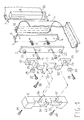
- the connector holder with spatial position adjustment comprises a first supporting plate 1, second supporting plate 2, supporting element 3, and mounting base 4.
- the plate 1 has a generally rectangular shape and has two calibrated cylindrical alignment sockets 5, 6 on its end adapted to receive two alignment pins 7, 8 respectively rigid with a printed circuit board 80 having a connector 9 for printed circuit boards with one- or two-line contact.
- a connector 10 Fastened to one face of the plate 1 by means of screws is a connector 10 intended for coupling to the connector 9 and having a flexible ribbon cable 11 welded thereto which is terminated with a second connector 12.
- the connectors 9 and 10 are positioned in an accurate permanent way relative to the pins 7, 8 and the sockets 5, 6 such that the insertion of the alignment pins into the sockets will ensure coaxial alignment of the two connectors.
- the plate 1 is made fast with the plate 2, also generally rectangular in shape, by means of guide pins 13, 14 threaded perpendicularly into the plate 1 at the midsection of the connector 10 in the direction of its length and fitting slidably into two cylindrical housings 15, 16 in the plate 2.
- Two compression coil springs 17, 18 are wound around the pins 12, 14 between the two plates 1 and 2.
- the pins 13, 14 are terminated with two retainer heads 19, 20 which prevent the plate 2 from slipping off the pins and ensure a predetermined spring loading directed to hold the two plates 1 and 2 parallel with and spaced apart from each other.
- the maximum deviation from relative parallelism of the two plates and variation in relative rotation about a parallel axis to the direction of elongation of the plates and the connectors can be set.
- the plate 2 has two cylindrical turrets 21, 22 of predetermined height which respectively fit with a predetermined clearance into two cylindrical openings 23, 24 in the supporting element 3.
- the element 3 is preferably a die-casting comprising a U-shaped bracket ending in two flanges 25, 26 whose thickness is equal to the height of the turrets 21, 22 and in which the openings 23, 24 are formed.
- Two screws 27, 28 with lockwashers 29, 30 are threaded into corresponding sockets in the turrets 21, 22 and fasten in an unreleasable manner the supporting element 3 to the plate 2 leaving a predetermined clearance across the mating plane.
- the supporting element 3 may be provided with permanent or releasable means of fastening to a mechanical support such as a back panel or a frame.
- the supporting element 3 has hook-on teeth 31, 32 opposite to a retainer flange 33 to form a releasable bayonet fit into a base 4, in turn attached to a back panel or a frame by means of screws 39 and 40 or any equivalent arrangement.
- the base 4 has the general form of an elongate right parallelepipedon and has two fitting sockets 34, 35 complementary in shape of the teeth 31, 32 and provided with retainer teeth 36, 37.
- the hook-on teeth 31, 32 of the supporting element 3 fit into the sockets 34, 36 as the elements 3 and 4 are brought near in the perpendicular direction to the plane of the plates 1 and 2.
- the opposed arrangement of the retainer flange 33 and the teeth 31, 32 ensures that the base 4 and the supporting element 3 will interfit with freedom of relative translation parallel with the plane of the plates 1, 2 and along their direction of greater length.
- the two elements are also held in place by a screw 38, preferably a captive thumbscrew for manual screwing passed through a socket 41 formed in the flange 33 and engaged in a threaded socket 42 formed in the base 4.
- a screw 38 preferably a captive thumbscrew for manual screwing passed through a socket 41 formed in the flange 33 and engaged in a threaded socket 42 formed in the base 4.
- the connector 12 may also be provided with a spatially adjustable holder as described.
- the tapered end pins 7, 8 fit into the sockets 5 and 6 and align axially the aggregate including the connector 10 and plates 1 and 2 which is adapted to be translated relative to the supporting element 3 in the perpendicular plane of the plates to the direction of insertion.
- any tolerance in the depth of the printed circuit board, and hence in the depth of insertion, would be absorbed by the compliance of the plate 1 relative to the plate 2 along the direction of insertion.
- the thrust applied by the springs 17, 18 ensures that a predetermined, gradually higher insertion force is applied in coupling the two connectors together and the compliance of the plate 1 relative to the plate 2 ensures that the insertion force does not exceed an acceptable maximum value imposed by the elastic constant of the spring for the maximum foreseeable compression condition.
- the holder described has a further important advantage in that it ensures that during removal of the board 80 from its socket, the connector 10 cannot be entrained frictionally along with the plate but becomes disconnected from the connector 9 while staying fast with its support.
- Figure 2 shows by way of example a typical application wherein the holder described is employed to advantage.
- a data processing system comprises a plurality of electronic apparatus housed within a cabinet 60 which allows the apparatus to be accessed from the front 61, the rear, and through an upper opening 63.
- a back panel 64 Housed within the cabinet, at an intermediate location to the front and rear, is a back panel 64 which carries a mother board 65 which is arranged parallel with the top face of the cabinet and facing the upper opening 63.
- daughter boards Engaged by connectors with the mother board 65 are daughter boards arranged vertically and not shown in the drawing for clarity.
- a connector holder 67 of the kind described above is attached to the back panel 64 such that upon insertion of the board 66 into its housing, a connector of the board 66 will become coupled to the connector attached to the holder.
- the flexible ribbon cable of the holder will then make the connection to the mother board 65.
- the supporting element 3 may be provided with means for fastening it to the base 4 which are operable from one end or the front rather than from one side of the base 4 as shown.
- the element 3 may be provided with an end flange 50 for coupling to the upper front portion 51 of the base 4 with the element 3 engaged in the base 4.
- a screw 52 passed through the flange 50 with an axis oriented in the same direction as the connector direction of insertion is threaded into the base 4 and holds the two elements 3 and 4 in the relative engaged position.
- the element 3 may be provided with a wing 53 to overlap the head 54 of the base 4 where it would be retained by a screw 55 operable along the direction of greater length of the base 4.
- the supporting element 3, having no teeth 31, 32 and wing 33 in this case, may be attached directly to the back panel or the frame.
- the plate 1 is preferably provided with sockets 5 and 6 for alignment pins, but it would be possible to provide a plate 1 with alignment pins or even with a combination of one alignment pin and socket.
- the printed circuit board 80 to be connected may generally consist of some other type of electric apparatus equipped with a connector and alignment means.
Landscapes
- Engineering & Computer Science (AREA)
- Microelectronics & Electronic Packaging (AREA)
- Mounting Of Printed Circuit Boards And The Like (AREA)
- Coupling Device And Connection With Printed Circuit (AREA)
Claims (3)
- Eine Halterung (1, 2, 3) für einen Verbinder (10) mit einer räumlichen Einstellung der Position des Verbinders (10), mit folgenden Merkmalen:einer ersten Trageplatte (1), die auf einer Ebene liegt;einem ersten Verbinder (10), der an der ersten Platte (1) befestigt ist, wobei die erste Platte mit einer Ausrichtungseinrichtung (5, 6) versehen ist, die mit einer Ausrichtungseinrichtung (7, 8) auf einer ersten elektrischen Vorrichtung (80) zusammenwirkt, um mit dem ersten Verbinder (10) entlang einer vorbestimmten Einfügungsrichtung, die senkrecht zu der Ebene der ersten Platte ist, verbunden zu werden,einer zweiten Trageplatte (2), die parallel zu der ersten Platte ist;einer ersten mechanischen Kopplungseinrichtung (13, 14) zum Miteinanderkoppeln der ersten und zweiten Platte und zum Ermöglichen eines vorbestimmten Ausmaßes einer Relativbewegung der ersten und zweiten Platte in der vorbestimmten Einfügungsrichtung und einer Variation der parallelen Anordnung der ersten und zweiten Platte;einer elastischen Einrichtung (17, 18) zum Ausüben einer vorbestimmten Trennungskraft zwischen der ersten und zweiten Platte;einem Trageelement (3),einer zweiten mechanischen Kopplungseinrichtung (27, 28, 29, 30, 21, 22) zum Koppeln der zweiten Platte (2) mit dem Trageelement (3), um dadurch ein vorbestimmtes Ausmaß einer Relativbeweglichkeit in der Ebene der zweiten Platte (2) vorzusehen, undeiner Befestigungseinrichtung (31, 32) zum Befestigen des Trageelements (3) an einem Tragebauglied (4), undeiner flexiblen elektrischen Verbindung (11), die elektrisch mit dem ersten Verbinder (10) zur Verbindung mit einer zweiten elektrischen Vorrichtung verbunden ist.
- Eine Halterung gemäß Anspruch 1, bei der die erste mechanische Kopplungseinrichtung ein Paar von Stiften (13, 14) aufweist, die senkrecht zu der Ebene der ersten und zweiten Platte sind, die starr bezüglich der ersten Platte sind und verschiebbar durch Öffnungen (15, 16) in der zweiten Platte (2) verlaufen, und wobei die elastische Einrichtung ein Paar von Kompressionsschraubenfedern (17, 18) aufweist, die um einen Stift (13, 14) des Paars gewunden und zwischen der ersten und zweiten Platte angeordnet sind.
- Eine Halterung gemäß Anspruch 1 oder 2, bei der die Befestigungseinrichtung Einhakzähne (31, 32) für eine passende Ineingriffnahme mit dem Trageelement und Sockel (34, 35) für die Einhackzähne in einer Basis (4) des Tragebauglieds aufweist.
Priority Applications (2)
| Application Number | Priority Date | Filing Date | Title |
|---|---|---|---|
| EP94830339A EP0691704B1 (de) | 1994-07-07 | 1994-07-07 | Verbinderhalter mit räumlicher Einstellung der Lage des Verbinders |
| DE1994621525 DE69421525T2 (de) | 1994-07-07 | 1994-07-07 | Verbinderhalter mit räumlicher Einstellung der Lage des Verbinders |
Applications Claiming Priority (1)
| Application Number | Priority Date | Filing Date | Title |
|---|---|---|---|
| EP94830339A EP0691704B1 (de) | 1994-07-07 | 1994-07-07 | Verbinderhalter mit räumlicher Einstellung der Lage des Verbinders |
Publications (2)
| Publication Number | Publication Date |
|---|---|
| EP0691704A1 EP0691704A1 (de) | 1996-01-10 |
| EP0691704B1 true EP0691704B1 (de) | 1999-11-03 |
Family
ID=8218489
Family Applications (1)
| Application Number | Title | Priority Date | Filing Date |
|---|---|---|---|
| EP94830339A Expired - Lifetime EP0691704B1 (de) | 1994-07-07 | 1994-07-07 | Verbinderhalter mit räumlicher Einstellung der Lage des Verbinders |
Country Status (2)
| Country | Link |
|---|---|
| EP (1) | EP0691704B1 (de) |
| DE (1) | DE69421525T2 (de) |
Families Citing this family (3)
| Publication number | Priority date | Publication date | Assignee | Title |
|---|---|---|---|---|
| FR2762749B1 (fr) * | 1997-03-25 | 2000-08-11 | Whitaker Corp | Assemblage de connexion electrique |
| DE29721908U1 (de) * | 1997-12-11 | 1998-02-12 | Leopold Kostal GmbH & Co KG, 58507 Lüdenscheid | Anordnung betreffend eine elektrische und/oder elektronische Bauelemente tragende Elektrikplatte mit einem elektrischen Steckverbinder und einer Abdeckung |
| WO2008119393A1 (en) * | 2007-04-03 | 2008-10-09 | Telefonaktiebolaget Lm Ericsson (Publ) | Backplane to mate boards with different widths |
Citations (1)
| Publication number | Priority date | Publication date | Assignee | Title |
|---|---|---|---|---|
| US4580858A (en) * | 1985-05-09 | 1986-04-08 | System Development Corporation | Alignment fixture assembly for surface-mount connectors |
Family Cites Families (5)
| Publication number | Priority date | Publication date | Assignee | Title |
|---|---|---|---|---|
| US3433909A (en) * | 1967-08-24 | 1969-03-18 | Nasa | Separation simulator |
| US3596018A (en) * | 1969-06-25 | 1971-07-27 | Howard Gross | Electrical connection device for vehicles |
| FR2127328A5 (de) * | 1971-03-04 | 1972-10-13 | Materiel Telephonique | |
| AT389403B (de) * | 1987-05-06 | 1989-12-11 | Siemens Ag Oesterreich | Auswurfvorrichtung fuer die federleiste eines flachleitungs-steckverbinders |
| US5295839A (en) * | 1993-03-16 | 1994-03-22 | Hewlett-Packard Company | Method and system for interconnectingly engaging circuits |
-
1994
- 1994-07-07 EP EP94830339A patent/EP0691704B1/de not_active Expired - Lifetime
- 1994-07-07 DE DE1994621525 patent/DE69421525T2/de not_active Expired - Lifetime
Patent Citations (1)
| Publication number | Priority date | Publication date | Assignee | Title |
|---|---|---|---|---|
| US4580858A (en) * | 1985-05-09 | 1986-04-08 | System Development Corporation | Alignment fixture assembly for surface-mount connectors |
Also Published As
| Publication number | Publication date |
|---|---|
| DE69421525T2 (de) | 2000-07-06 |
| DE69421525D1 (de) | 1999-12-09 |
| EP0691704A1 (de) | 1996-01-10 |
Similar Documents
| Publication | Publication Date | Title |
|---|---|---|
| JPH08236228A (ja) | 電気コネクタ・アセンブリ | |
| KR100479136B1 (ko) | 범용인터페이스시험어댑터 | |
| US4971563A (en) | Modular backplane assemblies for computers | |
| US5967824A (en) | Mechanism for inserting or removing I/O cards with internal connectors | |
| US4925400A (en) | ESD protected electrical connector and ESD grounding clip therefor, and circuit panel connector assembly and method of assembling same | |
| JPH08330032A (ja) | 基板用コネクタ | |
| CN108539451A (zh) | 卡缘连接器组件 | |
| JPH098500A (ja) | 回路カードをスナップ取付け解除可能な締付アセンブリ | |
| JP2001313122A (ja) | 電子相互接続アセンブリ用アダプタ | |
| JPH0779199B2 (ja) | 電子モジュール相互接続システム | |
| US6824418B2 (en) | Connector and electronic device and information processing apparatus using said connector | |
| EP0349125B1 (de) | Halterungsgehäuse für Kabelbaumverbinder | |
| US4807759A (en) | Package for an expandable remote interface unit | |
| EP0691704B1 (de) | Verbinderhalter mit räumlicher Einstellung der Lage des Verbinders | |
| US5221218A (en) | Edge-card connector | |
| US6053760A (en) | Universal device for mounting circuit cards in a computer or like electrical machine | |
| US5873739A (en) | Direct circuit to circuit stored energy connector | |
| US5711677A (en) | Multi-functional I/O card guide | |
| US11617279B2 (en) | Brake for an electronic component | |
| US4898538A (en) | Self aligning connector | |
| US12603448B2 (en) | Card connector | |
| US5513079A (en) | Mass termination of signals from electronic systems to devices under test | |
| US6802722B2 (en) | Retainer bracket for connectors | |
| JPH0212784A (ja) | 通電機構 | |
| CN113140932B (zh) | 浮动式导引插入连接器 |
Legal Events
| Date | Code | Title | Description |
|---|---|---|---|
| PUAI | Public reference made under article 153(3) epc to a published international application that has entered the european phase |
Free format text: ORIGINAL CODE: 0009012 |
|
| AK | Designated contracting states |
Kind code of ref document: A1 Designated state(s): DE FR GB IT |
|
| 17P | Request for examination filed |
Effective date: 19960503 |
|
| GRAG | Despatch of communication of intention to grant |
Free format text: ORIGINAL CODE: EPIDOS AGRA |
|
| 17Q | First examination report despatched |
Effective date: 19980929 |
|
| GRAG | Despatch of communication of intention to grant |
Free format text: ORIGINAL CODE: EPIDOS AGRA |
|
| GRAH | Despatch of communication of intention to grant a patent |
Free format text: ORIGINAL CODE: EPIDOS IGRA |
|
| RAP1 | Party data changed (applicant data changed or rights of an application transferred) |
Owner name: BULL HN INFORMATION SYSTEMS ITALIA S.P.A. |
|
| GRAH | Despatch of communication of intention to grant a patent |
Free format text: ORIGINAL CODE: EPIDOS IGRA |
|
| GRAA | (expected) grant |
Free format text: ORIGINAL CODE: 0009210 |
|
| AK | Designated contracting states |
Kind code of ref document: B1 Designated state(s): DE FR GB IT |
|
| RAP2 | Party data changed (patent owner data changed or rights of a patent transferred) |
Owner name: BULL S.A. |
|
| REF | Corresponds to: |
Ref document number: 69421525 Country of ref document: DE Date of ref document: 19991209 |
|
| ITF | It: translation for a ep patent filed | ||
| ET | Fr: translation filed | ||
| PLBE | No opposition filed within time limit |
Free format text: ORIGINAL CODE: 0009261 |
|
| STAA | Information on the status of an ep patent application or granted ep patent |
Free format text: STATUS: NO OPPOSITION FILED WITHIN TIME LIMIT |
|
| 26N | No opposition filed | ||
| REG | Reference to a national code |
Ref country code: GB Ref legal event code: IF02 |
|
| PGFP | Annual fee paid to national office [announced via postgrant information from national office to epo] |
Ref country code: GB Payment date: 20130626 Year of fee payment: 20 |
|
| PGFP | Annual fee paid to national office [announced via postgrant information from national office to epo] |
Ref country code: DE Payment date: 20130621 Year of fee payment: 20 |
|
| PGFP | Annual fee paid to national office [announced via postgrant information from national office to epo] |
Ref country code: FR Payment date: 20130722 Year of fee payment: 20 |
|
| PGFP | Annual fee paid to national office [announced via postgrant information from national office to epo] |
Ref country code: IT Payment date: 20130628 Year of fee payment: 20 |
|
| REG | Reference to a national code |
Ref country code: DE Ref legal event code: R071 Ref document number: 69421525 Country of ref document: DE |
|
| REG | Reference to a national code |
Ref country code: GB Ref legal event code: PE20 Expiry date: 20140706 |
|
| PG25 | Lapsed in a contracting state [announced via postgrant information from national office to epo] |
Ref country code: DE Free format text: LAPSE BECAUSE OF EXPIRATION OF PROTECTION Effective date: 20140708 |
|
| PG25 | Lapsed in a contracting state [announced via postgrant information from national office to epo] |
Ref country code: GB Free format text: LAPSE BECAUSE OF EXPIRATION OF PROTECTION Effective date: 20140706 |