EP0692697A2 - An eccentricity gauge - Google Patents
An eccentricity gauge Download PDFInfo
- Publication number
- EP0692697A2 EP0692697A2 EP95304640A EP95304640A EP0692697A2 EP 0692697 A2 EP0692697 A2 EP 0692697A2 EP 95304640 A EP95304640 A EP 95304640A EP 95304640 A EP95304640 A EP 95304640A EP 0692697 A2 EP0692697 A2 EP 0692697A2
- Authority
- EP
- European Patent Office
- Prior art keywords
- cable
- conductor core
- core
- conductor
- magnetic fields
- Prior art date
- Legal status (The legal status is an assumption and is not a legal conclusion. Google has not performed a legal analysis and makes no representation as to the accuracy of the status listed.)
- Withdrawn
Links
- 239000004020 conductor Substances 0.000 claims abstract description 51
- 238000000034 method Methods 0.000 claims abstract description 29
- 230000003287 optical effect Effects 0.000 claims abstract description 26
- 230000001939 inductive effect Effects 0.000 claims abstract description 18
- 238000001125 extrusion Methods 0.000 claims abstract description 15
- 230000006698 induction Effects 0.000 claims description 9
- 230000005540 biological transmission Effects 0.000 claims description 4
- 230000004907 flux Effects 0.000 claims description 3
- 239000011248 coating agent Substances 0.000 abstract description 8
- 238000000576 coating method Methods 0.000 abstract description 8
- 238000005259 measurement Methods 0.000 abstract description 6
- 238000012937 correction Methods 0.000 abstract 1
- 239000004033 plastic Substances 0.000 description 4
- 229920003023 plastic Polymers 0.000 description 4
- RYGMFSIKBFXOCR-UHFFFAOYSA-N Copper Chemical compound [Cu] RYGMFSIKBFXOCR-UHFFFAOYSA-N 0.000 description 1
- 229910000831 Steel Inorganic materials 0.000 description 1
- 239000004411 aluminium Substances 0.000 description 1
- XAGFODPZIPBFFR-UHFFFAOYSA-N aluminium Chemical compound [Al] XAGFODPZIPBFFR-UHFFFAOYSA-N 0.000 description 1
- 229910052782 aluminium Inorganic materials 0.000 description 1
- 230000015572 biosynthetic process Effects 0.000 description 1
- 238000010073 coating (rubber) Methods 0.000 description 1
- 230000003750 conditioning effect Effects 0.000 description 1
- 238000010276 construction Methods 0.000 description 1
- 238000001816 cooling Methods 0.000 description 1
- 239000010949 copper Substances 0.000 description 1
- 229910052802 copper Inorganic materials 0.000 description 1
- 230000001419 dependent effect Effects 0.000 description 1
- 230000000694 effects Effects 0.000 description 1
- 239000011810 insulating material Substances 0.000 description 1
- 238000004519 manufacturing process Methods 0.000 description 1
- 238000012544 monitoring process Methods 0.000 description 1
- 239000006223 plastic coating Substances 0.000 description 1
- 239000010959 steel Substances 0.000 description 1
- 230000000007 visual effect Effects 0.000 description 1
Images


Classifications
-
- G—PHYSICS
- G01—MEASURING; TESTING
- G01B—MEASURING LENGTH, THICKNESS OR SIMILAR LINEAR DIMENSIONS; MEASURING ANGLES; MEASURING AREAS; MEASURING IRREGULARITIES OF SURFACES OR CONTOURS
- G01B7/00—Measuring arrangements characterised by the use of electric or magnetic techniques
- G01B7/30—Measuring arrangements characterised by the use of electric or magnetic techniques for measuring angles or tapers; for testing the alignment of axes
- G01B7/31—Measuring arrangements characterised by the use of electric or magnetic techniques for measuring angles or tapers; for testing the alignment of axes for testing the alignment of axes
- G01B7/312—Measuring arrangements characterised by the use of electric or magnetic techniques for measuring angles or tapers; for testing the alignment of axes for testing the alignment of axes for measuring eccentricity, i.e. lateral shift between two parallel axes
Definitions
- the present invention relates to the formation of an electrical cable by extrusion techniques and particularly to a method and apparatus for monitoring the position of the conductor core of the cable in relation to the outer extruded coating in order that the extrusion process can be controlled to maintain the core on the central axis of the cable.
- an inner conductor wire such as of copper, aluminium, steel or other electrically conductive material is coated with an insulating material of plastics, rubber and the like, the coating being applied as by extrusion from an extruder through which the inner conductor is passed at a predetermined speed.
- the finished product coming from the extruder then undergoes a cooling process which cools the hot plastics or rubber coating issuing from the hot extruder whereafter the product is wound onto a drum or reel.
- the inner conductor is located along the central axis of the cable.
- apparatus for determining the position of the conductor core of an electrical cable being formed in an extrusion process comprising optical means for transmitting a beam of light towards the cable, detector means for receiving either the beam reflected from the cable or that portion of the beam not obscured by the cable in transmission and providing output signals representative of the position of the outer surface of the cable in relation to the optical means, electrical inductive means for inducing magnetic fields with converging lines of force in the vicinity of the cable, means arranged to intercept the convergence of said lines of force for detecting variation in the field strength of said magnetic fields as a result of movement of the conductor core through said fields corresponding to a change in position of the conductor core from a desired location within the cable thereby to provide a measure of the position of the conductor core in relation to the inductive means, and means for relating the position of said conductor core to the position of the outer surface of the cable whereby to determine the eccentricity or off-set position of the conductor core with respect to said desired location within the cable.
- a method for determining the position of the conductor of an electrical cable being formed in an extrusion process comprising transmitting a beam of light towards the cable, providing output signals representative of the position of the outer surface of the cable and corresponding either to the reflection of the beam from the cable or that portion of the transmitted beam not obscured by the cable in transmission, providing induced magnetic fields in the vicinity of the cable, determining the variation in said magnetic fields brought about by a change in position of the conductor core moving from a desired location within the cable through the induced magnetic fields to provide a measure of the position of the conductor core, and determining the position of the conductor core with respect to the desired location by relating the position of the outer surface of the cable to the position of the conductor core.
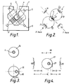
- the measuring system 1 shown in Fig 1 is designed to determine the eccentricity or off-centre axial position of the core of a moving electrical cable in an extrusion process using optical and electrical measuring techniques.
- It comprises a first light source 2 for emitting a beam of light directed at a moving cable 3 provided with a conductor core 4.
- a photosensitive detector 5 is positioned in the path of the beam from the light source 2 such that the detector 5 receives that portion of the light beam from light source 2 which is not obscured by the cable 3.
- a second light source 6 transmits a beam of light across the cable 3, the beam of light from the light source 6 having an axis at 90° to the axis of the light beam from the other light source 2.
- a photosensitive device 7 is positioned on the axis of the light beam from the light source 6, and this photosensitive device 7 receives that portion of the light beam from the light source 6 which is not obscured by the cable 3.
- the outputs from the photosensitive devices 5 and 7 may be used to determine the diameter or width of the cable 3 and thus the position of the outer surface of the cable at the respective ends of that diameter or width.
- the measuring system 1 also incorporates a pair of induction coils 8 and 9 disposed on either side of cable 3, and on the same axis as that of the parallel scanning beam emitted by light source 2 and received by the photosensitive detector 5.
- induction coils 10 and 11 may be positioned on either side of the cable 3 and on the axis corresponding to the axis of the parallel scanning beam emitted by light source 6 and detected by photosensitive detector 7.
- Magnetic fields induced during passage of current, preferably ac current, through the induction coils 8, 9, 10 and 11 are used to determine the position of the inner core 4 of the cable 3.
- a current I1 passed through coil 8 and a current I2 passed through coil 9 will set up magnetic fields 12 and 13 respectively in opposition to one another and depending on the direction of the current passing through the coils I1 and I2.
- the system is designed such that when the conductor 4 is midway between the coils 8 and 9, the current I1 and I2 are equal.
- a similar movement along the axis of the optical beam emitted by light source 6 can be determined by means of induction coils 10 and 11.
- Figs 3 and 4 illustrate the way in which the determination of the position of the outer cable by the optical system of Fig 1 and the determination of the position of the conductor core 4 of the cable 3 by means of the system shown in Fig 2, is utilised to measure the eccentricity of the cable core 4.
- the desired correct position of the conductor core 4 is along the central axis of the cable 14 therein depicted.
- the eccentricity of the cable is defined by any position off this central axis as shown in Fig 3, namely to the position 16 in relation to the outer surface of the cable 15.
- the position of the outer surface of the electrical cable 17 is determined optically by an optical measurement of distances 'a' and 'b', that is between the induction coil 19 on one side of the cable and induction coil 20 on the other side of the cable and lying on the optical axis of the transmitted light beam, for example, light source 2 shown in Fig 1.
- the position of the inner core 21 of the electrical cable is measured by induction coils 19 and 20 as explained with reference to Fig 2 and these are differences 'f' and 'c' as shown.
- the optical and electrical measuring system 1 as described with reference to Figs 1 and 2 is shown in perspective view in Fig 5.
- the measurements of the eccentricity of the conductor core 4 of the cable 3 are performed on a continuous basis and processed in an indicator unit 22 provided with a cathode ray tube 23 which is set to display a cross sectional view of the cable 3 with conductor core 4 as shown.
- both the aforementioned inductive and optical systems may be placed in an enclosure 24 which may then be rotated around the cable 3 in order to effect an all around measure of the eccentricity of the cable product.
- the enclosure 24 as shown in Fig 6 is, in a practical arrangement, integral with a rotary component 25 as shown in Fig 7, which is driven by means of an electric motor 26 and an interconnecting driving belt 27.
- the enclosure or housing 24 is thereby rotated around the cable 3 at right angles to its direction of movement.
- the output from the optical and inductive components may then be transferred through a set of slip rings or otherwise a non-contact rotary transformer 28 to a processing unit 29 which will condition and calculate the eccentricity of the product as desired.
- a transducer 30 is installed on the rotary component which will provide an output corresponding to the position of the housing 24. This output may then be transferred through the set of slip rings or rotary transformer 28 to the processing unit 29 and thereby at all times the eccentricity as well as the angular position of the housing 24 corresponding to that eccentricity may be calculated and displayed on the processing unit 29.
- FIG. 8-13 A further embodiment of an eccentricity gauge according to the invention is as depicted in Figs 8-13.
- a section of cable product 3 as before is shown having an eccentric metallic conductor core 4 within the plastic or insulating coating of the cable.
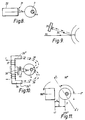
- the method for measuring the distance from the edge 31 of an optical unit 32 to the surface of the plastic coating 17 functions by means of a laser beam 33 emitted from the front face of the unit 32 directed towards a portion of surface of the product 17 wherefrom the beam is reflected towards the face of the unit 32.
- the reflected laser beam 34 then falls upon, for example, a CCD 35 at a nominal position. If the surface of the cable then moves to a different position, the reflected beam 34 will move accordingly to a different position upon the CCD 35 and, thereby, a measure may be obtained of the positional change of the surface of the cable 17.
- the inductive system as employed in the second embodiment is as shown in Fig 10, whereby the magnetic field utilised in the measurement of the distance of the conductor core 4 from the inductive system is generated by means of an E-core 36 with a coil 37 wound on the core 36 to either side of the central limb 36' in such a way that when a current flows in the coil 37 a magnetic field 38, 39 will appear from the two external limbs 36'' of the E-core 36 flowing past the cable conductor core 4 and entering the central portion 36' of the E-core 36 as shown.
- a small search coil 40 which will monitor the magnetic flux flowing through itself linking back to the central limb 36'. This magnetic flux will be sensitively dependent on the distance and position of the cable core 4 within the magnetic field 38, 39 and thus the electrical output generated in the search coil 40 will be a proportional measure of the position of the cable core 4 within the magnetic field 38, 39 and hence of the distance of the cable core 4 from the search coil 40.
- Fig 11 shows this fixed datum 41 from which (a) is the distance of the cable surface and (b) is the distance of the conductor core.
- Fig 12 shows a construction according to this method and apparatus having opto-inductive components positioned in space such that the required measurement may be effected.
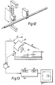
- Fig 13 shows a housing 42 containing the opto-inductive components, which housing 42 may be mounted on a rotating device 43, rotatable in a plane at right angles to the direction of extension of the cable product 3.
- An electric motor 44 may then drive the housing 42 using a time belt or the like 45 in a complete circle around the product 3.
- a transducer 46 is installed such that the position of the housing 42 is known at all times.
- Both outputs from the opto-inductive components as well as the output from the transducer 46 are then transferred through slip-rings or otherwise rotary non-contact transformers 47 into a conditioning and processing unit 48 which will display the eccentricity 49 as well as the angular position 50 of the housing 42 corresponding to that eccentricity on displays.
- this processing unit 48 may be fed to a visual display unit 51 which may then display a picture corresponding to the actual cable product 3 in sectional form.
- the invention as described above with reference to the preferred embodiments may be seen in summary to comprise a method and apparatus for measuring and displaying the eccentricity of a metallic conductor within an insulating coating during an extrusion process.
- the apparatus and method utilise optical means for detecting the position of the outer surface of the travelling cable and inductive means for detecting the position of the conductor cable and, by solving mathematical equations, the amount of eccentricity of the conductor within the plastics or insulating coating may be derived.
- the scanning optical technique determines the position of the outer surface of the cable within the optical limits of the apparatus and the inductive technique determining the position of the conducting core within the inductive limits of the apparatus, by which the position of the electrical conductor within the optical field is determined.
- the optical means which determine the position of the outer surface of the cable and the inductive means which determine the inner conductor of the cable may operate in two planes at right angles to each other.
- An out of balance signal may be obtained in these two planes for feed back purposes to control cable eccentricity.
Landscapes
- Physics & Mathematics (AREA)
- General Physics & Mathematics (AREA)
- Length Measuring Devices By Optical Means (AREA)
Abstract
Description
- The present invention relates to the formation of an electrical cable by extrusion techniques and particularly to a method and apparatus for monitoring the position of the conductor core of the cable in relation to the outer extruded coating in order that the extrusion process can be controlled to maintain the core on the central axis of the cable.
- During the manufacture of an electrical cable by means of continuous extrusion, an inner conductor wire such as of copper, aluminium, steel or other electrically conductive material is coated with an insulating material of plastics, rubber and the like, the coating being applied as by extrusion from an extruder through which the inner conductor is passed at a predetermined speed.
- The finished product coming from the extruder then undergoes a cooling process which cools the hot plastics or rubber coating issuing from the hot extruder whereafter the product is wound onto a drum or reel.
- To preserve the electrical and mechanical characteristics of the cable, it is important that the inner conductor is located along the central axis of the cable.
- It is accordingly an object of the present invention to provide a method and apparatus for determining the position of the conductor core of an electrical cable during an extrusion process so as to ensure that it is maintained in a central cable axial position during the process.
- According to one aspect of the present invention, there is provided apparatus for determining the position of the conductor core of an electrical cable being formed in an extrusion process comprising optical means for transmitting a beam of light towards the cable, detector means for receiving either the beam reflected from the cable or that portion of the beam not obscured by the cable in transmission and providing output signals representative of the position of the outer surface of the cable in relation to the optical means, electrical inductive means for inducing magnetic fields with converging lines of force in the vicinity of the cable, means arranged to intercept the convergence of said lines of force for detecting variation in the field strength of said magnetic fields as a result of movement of the conductor core through said fields corresponding to a change in position of the conductor core from a desired location within the cable thereby to provide a measure of the position of the conductor core in relation to the inductive means, and means for relating the position of said conductor core to the position of the outer surface of the cable whereby to determine the eccentricity or off-set position of the conductor core with respect to said desired location within the cable.
- According to another aspect of the present invention there is also provided a method for determining the position of the conductor of an electrical cable being formed in an extrusion process comprising transmitting a beam of light towards the cable, providing output signals representative of the position of the outer surface of the cable and corresponding either to the reflection of the beam from the cable or that portion of the transmitted beam not obscured by the cable in transmission, providing induced magnetic fields in the vicinity of the cable, determining the variation in said magnetic fields brought about by a change in position of the conductor core moving from a desired location within the cable through the induced magnetic fields to provide a measure of the position of the conductor core, and determining the position of the conductor core with respect to the desired location by relating the position of the outer surface of the cable to the position of the conductor core.
- The invention will now be described in preferred detail with reference to the accompanying drawings wherein,
- Fig 1 depicts a measuring system in end view in accordance with a first embodiment of the invention;
- Fig 2 illustrates how induction coils of the measuring system of Fig 1 are positioned around the travelling electrical cable;
- Figs 3 and 4 illustrate how the eccentricity of the conductor core of the travelling electrical cable may be calculated using the measuring system of the invention in relation to a central position;
- Fig 5 is a perspective view of generalised illustration of the measuring system as shown in Fig 1;
- Fig 6 depicts a housing for the opto-inductive means of the measuring system;
- Fig 7 depicts a schematic view of the measuring system incorporating the housing of Fig 6;
- Fig 8 depicts a laser optical device in relation to the cable according to a measuring system in accordance with a second embodiment of the invention;
- Fig 9 depicts an optical detector matched with the laser optical system of Fig 8;
- Fig 10 shows the inductive means of the second measuring system;
- Fig 11 shows the datum point in reference to the cable;
- Fig 12 depicts an arrangement of the optical and inductive means of the second measuring system; and
- Fig 13 illustrates a schematic depiction of the measuring system according to this second embodiment.
- The
measuring system 1 shown in Fig 1 is designed to determine the eccentricity or off-centre axial position of the core of a moving electrical cable in an extrusion process using optical and electrical measuring techniques. - It comprises a
first light source 2 for emitting a beam of light directed at a movingcable 3 provided with aconductor core 4. - A
photosensitive detector 5 is positioned in the path of the beam from thelight source 2 such that thedetector 5 receives that portion of the light beam fromlight source 2 which is not obscured by thecable 3. - A
second light source 6 transmits a beam of light across thecable 3, the beam of light from thelight source 6 having an axis at 90° to the axis of the light beam from theother light source 2. - A photosensitive device 7 is positioned on the axis of the light beam from the
light source 6, and this photosensitive device 7 receives that portion of the light beam from thelight source 6 which is not obscured by thecable 3. - The outputs from the
photosensitive devices 5 and 7 may be used to determine the diameter or width of thecable 3 and thus the position of the outer surface of the cable at the respective ends of that diameter or width. - The
measuring system 1 also incorporates a pair ofinduction coils 8 and 9 disposed on either side ofcable 3, and on the same axis as that of the parallel scanning beam emitted bylight source 2 and received by thephotosensitive detector 5. -
Further induction coils 10 and 11 may be positioned on either side of thecable 3 and on the axis corresponding to the axis of the parallel scanning beam emitted bylight source 6 and detected by photosensitive detector 7. - Magnetic fields induced during passage of current, preferably ac current, through the
induction coils inner core 4 of thecable 3. - Thus, for example, a current I₁ passed through coil 8 and a current I₂ passed through
coil 9 will set upmagnetic fields - The system is designed such that when the
conductor 4 is midway between thecoils 8 and 9, the current I₁ and I₂ are equal. - If the
conductor core 4 moves away from its position and along the axis between thecoils 8 and 9, i.e., along the optical axis between thelight source 2 and thedetector 5, currents I₁ and I₂ will change relative to one another. - By measuring this difference it is possible to deduce a change of position of the
conductor 4 along the axis of the light beam emitted bylight source 2. - A similar movement along the axis of the optical beam emitted by
light source 6 can be determined by means ofinduction coils 10 and 11. - Figs 3 and 4 illustrate the way in which the determination of the position of the outer cable by the optical system of Fig 1 and the determination of the position of the
conductor core 4 of thecable 3 by means of the system shown in Fig 2, is utilised to measure the eccentricity of thecable core 4. - Thus, as illustrated in Fig 3, the desired correct position of the
conductor core 4 is along the central axis of thecable 14 therein depicted. - The eccentricity of the cable is defined by any position off this central axis as shown in Fig 3, namely to the
position 16 in relation to the outer surface of thecable 15. - With reference to Fig 4, consider an
electrical cable 17 moving in an extrusion process and wherein theinner conductor 21 has moved off-centre. - The position of the outer surface of the
electrical cable 17 is determined optically by an optical measurement of distances 'a' and 'b', that is between theinduction coil 19 on one side of the cable andinduction coil 20 on the other side of the cable and lying on the optical axis of the transmitted light beam, for example,light source 2 shown in Fig 1. - The position of the
inner core 21 of the electrical cable is measured byinduction coils - Eccentricity e of the
inner core 21 is defined by the equation
- The optical and
electrical measuring system 1 as described with reference to Figs 1 and 2 is shown in perspective view in Fig 5. - The measurements of the eccentricity of the
conductor core 4 of thecable 3 are performed on a continuous basis and processed in anindicator unit 22 provided with acathode ray tube 23 which is set to display a cross sectional view of thecable 3 withconductor core 4 as shown. - Alternatively, as depicted in Figs 6 and 7, both the aforementioned inductive and optical systems may be placed in an
enclosure 24 which may then be rotated around thecable 3 in order to effect an all around measure of the eccentricity of the cable product. - The
enclosure 24 as shown in Fig 6 is, in a practical arrangement, integral with arotary component 25 as shown in Fig 7, which is driven by means of anelectric motor 26 and an interconnectingdriving belt 27. The enclosure orhousing 24 is thereby rotated around thecable 3 at right angles to its direction of movement. - The output from the optical and inductive components may then be transferred through a set of slip rings or otherwise a non-contact
rotary transformer 28 to aprocessing unit 29 which will condition and calculate the eccentricity of the product as desired. - A transducer 30 is installed on the rotary component which will provide an output corresponding to the position of the
housing 24. This output may then be transferred through the set of slip rings orrotary transformer 28 to theprocessing unit 29 and thereby at all times the eccentricity as well as the angular position of thehousing 24 corresponding to that eccentricity may be calculated and displayed on theprocessing unit 29. - A further embodiment of an eccentricity gauge according to the invention is as depicted in Figs 8-13.
- Referring to Fig 8, a section of
cable product 3 as before is shown having an eccentricmetallic conductor core 4 within the plastic or insulating coating of the cable. In this embodiment the method for measuring the distance from theedge 31 of anoptical unit 32 to the surface of theplastic coating 17 functions by means of alaser beam 33 emitted from the front face of theunit 32 directed towards a portion of surface of theproduct 17 wherefrom the beam is reflected towards the face of theunit 32. - As is clearly shown in Fig 9, the
reflected laser beam 34 then falls upon, for example, aCCD 35 at a nominal position. If the surface of the cable then moves to a different position, thereflected beam 34 will move accordingly to a different position upon theCCD 35 and, thereby, a measure may be obtained of the positional change of the surface of thecable 17. - The inductive system as employed in the second embodiment is as shown in Fig 10, whereby the magnetic field utilised in the measurement of the distance of the
conductor core 4 from the inductive system is generated by means of anE-core 36 with acoil 37 wound on thecore 36 to either side of the central limb 36' in such a way that when a current flows in the coil 37 amagnetic field 38, 39 will appear from the two external limbs 36'' of theE-core 36 flowing past thecable conductor core 4 and entering the central portion 36' of theE-core 36 as shown. - Located just in front of the central limb 36' is a
small search coil 40 which will monitor the magnetic flux flowing through itself linking back to the central limb 36'. This magnetic flux will be sensitively dependent on the distance and position of thecable core 4 within themagnetic field 38, 39 and thus the electrical output generated in thesearch coil 40 will be a proportional measure of the position of thecable core 4 within themagnetic field 38, 39 and hence of the distance of thecable core 4 from thesearch coil 40. - The known positions of, for example, the
optical unit 32 and thesearch coil 40 will then allow arelative datum plane 41 to be defined. - Therefore, again an opto-inductive method of measurement is provided, on the one hand measuring the distance of the
surface 17 of the product from thedatum 41 by optical means, and on the other hand, measuring the distance of the metallic conductor core from thatsame datum 41 by magnetic inductive means. - Fig 11 shows this
fixed datum 41 from which (a) is the distance of the cable surface and (b) is the distance of the conductor core. - Fig 12 shows a construction according to this method and apparatus having opto-inductive components positioned in space such that the required measurement may be effected.
- Fig 13 shows a housing 42 containing the opto-inductive components, which housing 42 may be mounted on a
rotating device 43, rotatable in a plane at right angles to the direction of extension of thecable product 3. - An
electric motor 44 may then drive the housing 42 using a time belt or the like 45 in a complete circle around theproduct 3. Atransducer 46 is installed such that the position of the housing 42 is known at all times. - Both outputs from the opto-inductive components as well as the output from the
transducer 46 are then transferred through slip-rings or otherwise rotary non-contact transformers 47 into a conditioning andprocessing unit 48 which will display theeccentricity 49 as well as theangular position 50 of the housing 42 corresponding to that eccentricity on displays. - Furthermore, of course, the output of this
processing unit 48 may be fed to avisual display unit 51 which may then display a picture corresponding to theactual cable product 3 in sectional form. - The invention as described above with reference to the preferred embodiments may be seen in summary to comprise a method and apparatus for measuring and displaying the eccentricity of a metallic conductor within an insulating coating during an extrusion process. The apparatus and method utilise optical means for detecting the position of the outer surface of the travelling cable and inductive means for detecting the position of the conductor cable and, by solving mathematical equations, the amount of eccentricity of the conductor within the plastics or insulating coating may be derived.
- The scanning optical technique determines the position of the outer surface of the cable within the optical limits of the apparatus and the inductive technique determining the position of the conducting core within the inductive limits of the apparatus, by which the position of the electrical conductor within the optical field is determined.
- By incorporating a feed back loop, it is possible to control the extrusion process by adjusting the die head through which the cable coating is extruded onto the
conductor core 4 and thus correct for the eccentricity of the core within thecable 3. - The optical means which determine the position of the outer surface of the cable and the inductive means which determine the inner conductor of the cable may operate in two planes at right angles to each other.
- An out of balance signal may be obtained in these two planes for feed back purposes to control cable eccentricity.
Claims (5)
- Apparatus for determining the position of the conductor core of an electrical cable being formed in an extrusion process comprising optical means for transmitting a beam of light towards the cable, detector means for receiving either the beam reflected from the cable or that portion of the beam not obscured by the cable in transmission and providing output signals representative of the position of the outer surface of the cable in relation to the optical means, electrical inductive means for inducing magnetic fields with converging lines of force in the vicinity of the cable, means arranged to intercept the convergence of said lines of force for detecting variation in the field strength of said magnetic fields as a result of movement of the conductor core through said fields corresponding to a change in position of the conductor core from a desired location within the cable thereby to provide a measure of the position of the conductor core in relation to the inductive means, and means for relating the position of said conductor core to the position of the outer surface of the cable whereby to determine the eccentricity or off-set position of the conductor core with respect to said desired location within the cable.
- Apparatus as claimed in claim 1 wherein the lines of force of said induced magnetic fields are set up respectively between the outer limbs and the central limb of an E-core wound with a current carrying induction coil, said detecting means being a search coil placed adjacent the central limb of the E-core so that the convergent magnetic flux engendered by said fields threads the coil.
- Apparatus as claimed in claimed in claim 2 wherein in the case of beam reflection, said beam of light is a laser beam, a charged couple device being positioned to receive the reflected beam whereby to detect movements of the position of the outer surface of the cable corresponding to movements of the reflected beams along the charged couple device.
- Apparatus as claimed in any preceding claim mounted in a housing for rotation around the cable, and wherein a transducer is arranged to provide a measure of rotatable positions around the cable whereby to provide an all round determination of the eccentricity or off-set position of the conductor core with respect to said desired location within the cable.
- A method for determining the position of the conductor of an electrical cable being formed in an extrusion process comprising transmitting a beam of light towards the cable, providing output signals representative of the position of the outer surface of the cable and corresponding either to the reflection of the beam from the cable or that portion of the transmitted beam not obscured by the cable in transmission, providing induced magnetic fields in the vicinity of the cable, determining the variation in said magnetic fields brought about by a change in position of the conductor core moving from a desired location within the cable through the induced magnetic fields to provide a measure of the position of the conductor core, and determining the position of the conductor core with respect to the desired location by relating the position of the outer surface of the cable to the position of the conductor core.
Applications Claiming Priority (2)
| Application Number | Priority Date | Filing Date | Title |
|---|---|---|---|
| GB9413993 | 1994-07-12 | ||
| GB9413993A GB2291185A (en) | 1994-07-12 | 1994-07-12 | Eccentricity gauge |
Publications (2)
| Publication Number | Publication Date |
|---|---|
| EP0692697A2 true EP0692697A2 (en) | 1996-01-17 |
| EP0692697A3 EP0692697A3 (en) | 1996-06-19 |
Family
ID=10758168
Family Applications (1)
| Application Number | Title | Priority Date | Filing Date |
|---|---|---|---|
| EP95304640A Withdrawn EP0692697A3 (en) | 1994-07-12 | 1995-07-03 | An eccentricity gauge |
Country Status (2)
| Country | Link |
|---|---|
| EP (1) | EP0692697A3 (en) |
| GB (1) | GB2291185A (en) |
Cited By (13)
| Publication number | Priority date | Publication date | Assignee | Title |
|---|---|---|---|---|
| EP0801288A1 (en) * | 1996-04-12 | 1997-10-15 | Beta Instrument Company Limited | Thickness measuring device |
| WO2003085354A1 (en) * | 2002-04-08 | 2003-10-16 | Zumbach Electronic Ag | Contactless system for measuring centricity and diameter |
| RU2300737C1 (en) * | 2005-11-15 | 2007-06-10 | Общество с ограниченной ответственностью "Научно-исследовательский институт ЭРМИС" | Inductive optical transformer of electric cable eccentricity meter |
| DE102006027925A1 (en) * | 2006-03-10 | 2007-09-13 | Matthias Dipl.-Ing. Braun | Set-sensitive component`s e.g. roof rafter, movement detecting device for use in e.g. stadium roof, has detection device detecting position deviations between tensioning rope or tension wire |
| RU2422766C1 (en) * | 2010-03-01 | 2011-06-27 | Государственное образовательное учреждение высшего профессионального образования "Томский политехнический университет" | Inductive-optical transducer of electrical cable eccentricity metre |
| WO2017168236A1 (en) * | 2016-04-01 | 2017-10-05 | Schleuniger Holding Ag | Combination sensor |
| WO2017168237A1 (en) * | 2016-04-01 | 2017-10-05 | Schleuniger Holding Ag | Combination sensor |
| EP3376158A1 (en) * | 2017-03-17 | 2018-09-19 | La Farga Tub, S.L. | Positioning verification apparatus for metal tubular pieces, verification equipment and positioning verification method |
| CN110174043A (en) * | 2019-06-24 | 2019-08-27 | 黄圣扬 | Engineering pipeline offset detecting device based on cutting magnetic induction line principle |
| KR20200093750A (en) * | 2019-01-29 | 2020-08-06 | 금오공과대학교 산학협력단 | Apparatus for measuring eccentricity of metal body |
| CN114018182A (en) * | 2021-11-16 | 2022-02-08 | 广西广缆科技集团有限公司 | Power cable production deviation measuring system and deviation measuring method |
| CN114543657A (en) * | 2022-02-24 | 2022-05-27 | 博腾电子产品(成都)有限公司 | Wire eccentricity detection device and detection method |
| US11852594B2 (en) | 2018-04-13 | 2023-12-26 | Maillefer S.A. | Surface scanner, an arrangement and a method for surface defect detection of a cable |
Families Citing this family (1)
| Publication number | Priority date | Publication date | Assignee | Title |
|---|---|---|---|---|
| CN108151630A (en) * | 2018-03-15 | 2018-06-12 | 核工业理化工程研究院 | A kind of slewing element coaxial degree check device and method |
Family Cites Families (6)
| Publication number | Priority date | Publication date | Assignee | Title |
|---|---|---|---|---|
| DE2265046A1 (en) * | 1972-05-29 | 1976-02-19 | Krauss Maffei Ag | Contactless distance measuring device - between hovering vehicle and fixed armature rail uses magnet on vehicle energised with AC |
| DE2517709C3 (en) * | 1975-04-22 | 1979-07-12 | Harald 2800 Bremen Sikora | Device for measuring and regulating the wall thickness of insulated strings |
| JPS59108903A (en) * | 1982-12-14 | 1984-06-23 | Kawasaki Steel Corp | Method for detecting seamed position of seam welded steel pipe |
| CH667327A5 (en) * | 1984-06-18 | 1988-09-30 | Zumbach Electronic Ag | METHOD AND DEVICE FOR TESTING THE WALL THICKNESS OF AN INSULATING LAYER. |
| DE3942214A1 (en) * | 1989-12-21 | 1991-06-27 | Sikora Industrieelektronik | DEVICE FOR MEASURING THE ECCENTRICITY OF A SHEET SURROUNDED BY A PLASTIC MATERIAL |
| GB9303978D0 (en) * | 1993-02-26 | 1993-04-14 | Beta Instr Co | An eccentricity gauge |
-
1994
- 1994-07-12 GB GB9413993A patent/GB2291185A/en not_active Withdrawn
-
1995
- 1995-07-03 EP EP95304640A patent/EP0692697A3/en not_active Withdrawn
Non-Patent Citations (1)
| Title |
|---|
| None |
Cited By (17)
| Publication number | Priority date | Publication date | Assignee | Title |
|---|---|---|---|---|
| EP0801288A1 (en) * | 1996-04-12 | 1997-10-15 | Beta Instrument Company Limited | Thickness measuring device |
| WO2003085354A1 (en) * | 2002-04-08 | 2003-10-16 | Zumbach Electronic Ag | Contactless system for measuring centricity and diameter |
| US7068359B2 (en) | 2002-04-08 | 2006-06-27 | Zumbach Electronic Ag | Contactless system for measuring centricity and diameter |
| RU2300737C1 (en) * | 2005-11-15 | 2007-06-10 | Общество с ограниченной ответственностью "Научно-исследовательский институт ЭРМИС" | Inductive optical transformer of electric cable eccentricity meter |
| DE102006027925A1 (en) * | 2006-03-10 | 2007-09-13 | Matthias Dipl.-Ing. Braun | Set-sensitive component`s e.g. roof rafter, movement detecting device for use in e.g. stadium roof, has detection device detecting position deviations between tensioning rope or tension wire |
| RU2422766C1 (en) * | 2010-03-01 | 2011-06-27 | Государственное образовательное учреждение высшего профессионального образования "Томский политехнический университет" | Inductive-optical transducer of electrical cable eccentricity metre |
| US10466035B2 (en) | 2016-04-01 | 2019-11-05 | Schleuniger Holding Ag | Combination sensor |
| WO2017168236A1 (en) * | 2016-04-01 | 2017-10-05 | Schleuniger Holding Ag | Combination sensor |
| WO2017168237A1 (en) * | 2016-04-01 | 2017-10-05 | Schleuniger Holding Ag | Combination sensor |
| US10641593B2 (en) | 2016-04-01 | 2020-05-05 | Schleuniger Holding Ag | Combination sensor |
| EP3376158A1 (en) * | 2017-03-17 | 2018-09-19 | La Farga Tub, S.L. | Positioning verification apparatus for metal tubular pieces, verification equipment and positioning verification method |
| US11852594B2 (en) | 2018-04-13 | 2023-12-26 | Maillefer S.A. | Surface scanner, an arrangement and a method for surface defect detection of a cable |
| KR20200093750A (en) * | 2019-01-29 | 2020-08-06 | 금오공과대학교 산학협력단 | Apparatus for measuring eccentricity of metal body |
| CN110174043A (en) * | 2019-06-24 | 2019-08-27 | 黄圣扬 | Engineering pipeline offset detecting device based on cutting magnetic induction line principle |
| CN110174043B (en) * | 2019-06-24 | 2020-12-11 | 陈昱见 | Engineering pipeline deviation detection device based on cutting magnetic induction line principle |
| CN114018182A (en) * | 2021-11-16 | 2022-02-08 | 广西广缆科技集团有限公司 | Power cable production deviation measuring system and deviation measuring method |
| CN114543657A (en) * | 2022-02-24 | 2022-05-27 | 博腾电子产品(成都)有限公司 | Wire eccentricity detection device and detection method |
Also Published As
| Publication number | Publication date |
|---|---|
| GB9413993D0 (en) | 1994-08-31 |
| EP0692697A3 (en) | 1996-06-19 |
| GB2291185A (en) | 1996-01-17 |
Similar Documents
| Publication | Publication Date | Title |
|---|---|---|
| EP0801288B1 (en) | Thickness measuring device | |
| EP0692697A2 (en) | An eccentricity gauge | |
| US5530364A (en) | Cable partial discharge location pointer | |
| EP0612975B1 (en) | An eccentricity gauge | |
| US4593244A (en) | Determination of the thickness of a coating on a highly elongated article | |
| JPS6111606A (en) | Method and device for inspecting thickness of layer | |
| EP0129282A1 (en) | Measuring device for the "contactless" measurement of large thicknesses, for metal materials above the Curie temperature | |
| US4088952A (en) | Process and apparatus for determining the position of an elongated object with respect to a reference axis | |
| JP2019510232A (en) | Combination sensor | |
| US5532588A (en) | Cable eccentricity gauge including an E-shaped core and a sensor coil disposed between an outer tip of the central limb and the cable | |
| US7068359B2 (en) | Contactless system for measuring centricity and diameter | |
| EP0647951B1 (en) | Electrical cables | |
| JP2592564B2 (en) | Apparatus for continuously measuring the thickness of a conductive thin layer on a running insulating support in the form of fiber or tape without touching the layer | |
| JPH0436330B2 (en) | ||
| EP2902837B1 (en) | A high speed magnetic oscillating device | |
| GB2283323A (en) | Electrical cable insulation measurement | |
| JPH07257819A (en) | Method and apparatus for detecting remaining amount of long object | |
| US3902249A (en) | Calipers | |
| EP0241013B1 (en) | Apparatus for detecting surface microdefects in a metal workpiece | |
| JPH07159449A (en) | Method and instrument for measuring electric current | |
| GB2230612A (en) | Cable/rod measuring system | |
| JPS6234003A (en) | Method for measuring refractory lining profile of ceramic furnace container | |
| SU746173A1 (en) | Apparatus for measuring cylindrical article diameners | |
| SU712752A1 (en) | Once-through-type eddy-current transducer | |
| JPS609697Y2 (en) | Continuous induction liquid level gauge |
Legal Events
| Date | Code | Title | Description |
|---|---|---|---|
| PUAI | Public reference made under article 153(3) epc to a published international application that has entered the european phase |
Free format text: ORIGINAL CODE: 0009012 |
|
| AK | Designated contracting states |
Kind code of ref document: A2 Designated state(s): AT BE CH DE FR GB IT LI |
|
| PUAL | Search report despatched |
Free format text: ORIGINAL CODE: 0009013 |
|
| AK | Designated contracting states |
Kind code of ref document: A3 Designated state(s): AT BE CH DE FR GB IT LI |
|
| 17P | Request for examination filed |
Effective date: 19961216 |
|
| RAP1 | Party data changed (applicant data changed or rights of an application transferred) |
Owner name: BETA LASERMIKE LIMITED |
|
| 17Q | First examination report despatched |
Effective date: 19980925 |
|
| STAA | Information on the status of an ep patent application or granted ep patent |
Free format text: STATUS: THE APPLICATION IS DEEMED TO BE WITHDRAWN |
|
| 18D | Application deemed to be withdrawn |
Effective date: 19990206 |