EP0693165B1 - Glissiere de guidage a deplacement lineaire - Google Patents
Glissiere de guidage a deplacement lineaire Download PDFInfo
- Publication number
- EP0693165B1 EP0693165B1 EP94913548A EP94913548A EP0693165B1 EP 0693165 B1 EP0693165 B1 EP 0693165B1 EP 94913548 A EP94913548 A EP 94913548A EP 94913548 A EP94913548 A EP 94913548A EP 0693165 B1 EP0693165 B1 EP 0693165B1
- Authority
- EP
- European Patent Office
- Prior art keywords
- guide rail
- linear motion
- guide
- cover band
- band
- Prior art date
- Legal status (The legal status is an assumption and is not a legal conclusion. Google has not performed a legal analysis and makes no representation as to the accuracy of the status listed.)
- Expired - Lifetime
Links
- 239000000463 material Substances 0.000 claims abstract description 6
- 238000005096 rolling process Methods 0.000 claims description 10
- 239000000428 dust Substances 0.000 description 9
- 230000000873 masking effect Effects 0.000 description 8
- 239000002245 particle Substances 0.000 description 7
- 239000002390 adhesive tape Substances 0.000 description 4
- 238000004519 manufacturing process Methods 0.000 description 4
- 239000002184 metal Substances 0.000 description 4
- 229910000639 Spring steel Inorganic materials 0.000 description 3
- 238000009434 installation Methods 0.000 description 3
- 238000011109 contamination Methods 0.000 description 2
- 238000010616 electrical installation Methods 0.000 description 2
- 238000007789 sealing Methods 0.000 description 2
- 229910000831 Steel Inorganic materials 0.000 description 1
- 239000000853 adhesive Substances 0.000 description 1
- 230000001070 adhesive effect Effects 0.000 description 1
- 239000002313 adhesive film Substances 0.000 description 1
- 239000012790 adhesive layer Substances 0.000 description 1
- 230000000712 assembly Effects 0.000 description 1
- 238000000429 assembly Methods 0.000 description 1
- 230000015572 biosynthetic process Effects 0.000 description 1
- 239000003795 chemical substances by application Substances 0.000 description 1
- 238000010276 construction Methods 0.000 description 1
- 230000002349 favourable effect Effects 0.000 description 1
- MJIHNNLFOKEZEW-UHFFFAOYSA-N lansoprazole Chemical compound CC1=C(OCC(F)(F)F)C=CN=C1CS(=O)C1=NC2=CC=CC=C2N1 MJIHNNLFOKEZEW-UHFFFAOYSA-N 0.000 description 1
- 230000007774 longterm Effects 0.000 description 1
- 230000035515 penetration Effects 0.000 description 1
- 230000003014 reinforcing effect Effects 0.000 description 1
- 239000007787 solid Substances 0.000 description 1
- 239000010959 steel Substances 0.000 description 1
Images

Classifications
-
- F—MECHANICAL ENGINEERING; LIGHTING; HEATING; WEAPONS; BLASTING
- F16—ENGINEERING ELEMENTS AND UNITS; GENERAL MEASURES FOR PRODUCING AND MAINTAINING EFFECTIVE FUNCTIONING OF MACHINES OR INSTALLATIONS; THERMAL INSULATION IN GENERAL
- F16C—SHAFTS; FLEXIBLE SHAFTS; ELEMENTS OR CRANKSHAFT MECHANISMS; ROTARY BODIES OTHER THAN GEARING ELEMENTS; BEARINGS
- F16C29/00—Bearings for parts moving only linearly
- F16C29/08—Arrangements for covering or protecting the ways
- F16C29/082—Arrangements for covering or protecting the ways fixed to the way
-
- F—MECHANICAL ENGINEERING; LIGHTING; HEATING; WEAPONS; BLASTING
- F16—ENGINEERING ELEMENTS AND UNITS; GENERAL MEASURES FOR PRODUCING AND MAINTAINING EFFECTIVE FUNCTIONING OF MACHINES OR INSTALLATIONS; THERMAL INSULATION IN GENERAL
- F16C—SHAFTS; FLEXIBLE SHAFTS; ELEMENTS OR CRANKSHAFT MECHANISMS; ROTARY BODIES OTHER THAN GEARING ELEMENTS; BEARINGS
- F16C29/00—Bearings for parts moving only linearly
- F16C29/04—Ball or roller bearings
- F16C29/06—Ball or roller bearings in which the rolling bodies circulate partly without carrying load
- F16C29/0633—Ball or roller bearings in which the rolling bodies circulate partly without carrying load with a bearing body defining a U-shaped carriage, i.e. surrounding a guide rail or track on three sides
- F16C29/0635—Ball or roller bearings in which the rolling bodies circulate partly without carrying load with a bearing body defining a U-shaped carriage, i.e. surrounding a guide rail or track on three sides whereby the return paths are provided as bores in a main body of the U-shaped carriage, e.g. the main body of the U-shaped carriage is a single part with end caps provided at each end
Definitions
- the invention relates to a linear motion guide with a guide rail and a cross-sectionally substantially U-shaped slide which engages the guide rail and which is provided with rolling or rolling elements for support on the guide rail, the guide rail having coverable through openings for fastening elements for attaching the guide rail a carrier is provided, which open into a surface of the guide rail facing away from the carrier and which are arranged in the range of movement of the slide.
- Linear motion guides are used as standard for the linear guidance of components with high precision, e.g. for guiding machine assemblies on machine tools or for moving measuring heads. Linear motion guides are also used in environments with a high degree of contamination. In order to avoid that the rolling or rolling elements arranged in the slide get dirty, which leads to increased wear and possibly. measures would be taken to prevent the ingress of dirt or dust into the interior of the sled. For this purpose, lip seals are often provided on the two end faces of the slide perpendicular to the running direction, which slide along the surface of the guide rail and the side faces of the guide rail in order to scrape dust or dirt particles from the respective surface.
- the guide rail is provided with through openings for corresponding fastening elements for attaching the guide rail to a carrier.
- the through opening can, for example, be stepped for receiving a fastening screw with a screw head, since dust and dirt accumulate between the top of the screw head and the surface of the guide rail can, which may get into the interior of the guide carriage when it is just crossing the passage opening, it is known in a generic linear motion guide from DE 38 12 505 A1 to cover the passage openings on the surface, with the help of a strip-shaped plate which is inserted into a longitudinal groove corresponding to the plate cross section on the upper side of the guide rail, and which is screwed onto the guide rail by means of holding blocks on both plate ends.
- a corresponding fastening screw passes through an assigned through opening of the plate before it penetrates into a corresponding thread of the guide rail.
- the wiper seal slides along, usually under a relatively high contact pressure, to ensure that the particularly dirt-prone upper side of the guide rail is reliably scraped off. Nevertheless, it is not always ensured that dirt particles in the edge area or gap area do not get inside the slide.
- U-profiles for various purposes are known, such as.
- B. Plastic base profiles for reinforcing wooden strips (Georg Wurster: “Der brieflye Häfele”;1971; Nagold, page 7.32) or sheet steel and plastic profiles as duct lower parts and duct covers for electrical installation ducts (prospectus Lanz Oensingen AG, printed notice 0691-2000; Tehalit catalog 1992, pages 26 and 28; Henderl, Alfred, "The modern and correct electrical installation", 8th edition, Weghig, Heidelberg 1977, pages 168-171).
- the U-profiles cover either a solid support or a continuous cavity; higher precision is not important.
- the expert in the field of high-precision guide rails such as these.
- B. used in machine tools or measuring devices, no suggestions in the area of the base profiles or the installation channels will be expected to solve the problem of reducing the risk of contamination of the slide interior.
- the invention has for its object to provide a linear motion guide of the type mentioned, which reliably reduces the risk of dust and dirt particles entering the carriage while being easy to manufacture and assemble.
- a cover band which is pushed or snapped onto the guide rail and is formed from resilient band material, is provided, for engagement, from an upper part of the guide rail covering its entire central section, which is perpendicular to the longitudinal direction of the guide rail, and two edge sections which are angled inwards and parallel to the longitudinal direction of the guide rail an undercut in each of the two side surfaces of the guide rail that follow the top side of the guide rail in the width direction in the edge region between the top side and the side surface.
- the masking tape covers the entire upper side of the guide rail, so that the lip seal on the slide has a continuously smooth, flat upper side of the guide rail, and dust or dirt particles or even workpiece chips cannot adhere to the upper side when the linear motion guide is used on a processing machine and thus can be reliably stripped through the lip seal. It is advantageous that no longitudinal groove has to be worked into the top of the guide rail. Due to the spring-loaded engagement of the edge sections of the band material in the respective undercut on the side of the guide rail, the cover band and the guide rail are held together reliably. Installation is particularly easy.
- the cover band is only to be inserted in an inclined position with one edge section into the corresponding undercut and then tilted onto the top of the guide rail until the other edge section deflects into the corresponding undercut. At least in the case of relatively short guide rails, the cover strip can also be pushed onto the guide rail.
- a contact surface of the undercut for contact with the respective edge section forms an undercut angle with the surface that is greater than one between the middle section and the bend angle formed at the edge portion. Due to this measure, the outer edges of the edge sections always lie reliably against the contact surface of the undercut under the desired spring force.
- the undercut angle is approximately 3 to 10 °, preferably approximately 5 °, greater than the kink angle. It has been found to be particularly favorable if the kink angle is approximately 65 to 75 °, preferably approximately 70 °.
- the edge between the surface and the contact surface be rounded.
- the cover band consists of hardened spring band.
- the hardened spring band is characterized by high wear and temperature resistance. There is also no fear of a drop in spring force. It is also possible to use a fairly thin spring band with a thickness of 0.1 to 0.2, preferably approximately 0.15 mm, so that converting a linear motion guide by using the cover band generally does not require any other changes, in particular the lip seal .
- the outer edges of the two edge sections form a corresponding step with the contact surface with a step height corresponding to the masking tape thickness. However, since the step is not on the dirt-exposed top of the guide rail, but on the sides of the guide rail, and in addition protected in the respective undercut, there is no danger that dust or dirt particles will accumulate here, which could then penetrate into the interior of the slide.
- the invention also relates to a guide rail cover band for a linear movement guide, as specified in claims 8 to 10.
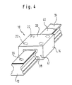
- the overall linear movement guide 10 shown in FIG. 4 consists of a guide rail 12 and a slide 14 which is movably mounted along the guide rail 12.
- the guide rail 12 is on a support 16, for example machine frame, indicated in FIGS. 1 and 2, with the aid of at least two fastening screws 18 attachable in the area of the two guide rail ends.
- the part to be moved linearly for example tool carrier or measuring device head, is on the guide slide 14.
- the carriage 14 is supported in the usual way on the rail 12 via rolling and rolling elements.
- the guide rail 12 is each provided with a corresponding, stepped through opening 32 which opens out into the upper side 34 of the guide rail 12 opposite the carrier 16, forming a relatively sharp annular edge 36.
- further screw fastenings may also be required between the guide rail ends, with corresponding through openings 32 in the guide rail 12.
- a lip seal 38 on both end faces 41 of the slide 14, essentially following the outline of the guide rail 12.
- a cover band 40 consisting of resilient band material, namely hardened spring band, is snapped onto the upper side 34 of the guide rail 12.
- the cover band 40 consists of a flat central section 42 with a width b slightly exceeding the corresponding width of the flat surface 34a of the upper side 34, and of two edge sections 44a and 44b.
- the edge sections 44a, 44b are each angled downward and towards one another with a kink angle a (FIG. 3) which is less than 90 ° and is approximately 65 to 75 °, preferably approximately 70 °.
- the respective edge section 44b lies on a contact surface 46 of an undercut 48 below the respective side edge 50 of the guide rail 12 between the upper side 34 and the long side 30.
- the contact surface 46 forms together with the flat upper side 34a an undercut angle B that is also less than 90 °. This is approximately 3 to 10 °, ideally approximately 5 ° larger than the kink angle ⁇ , ie approximately 75 °.
- a further inclined surface 51 adjoins the contact surface 46 in the direction away from the surface 34a, which forms an angle ( ⁇ + ⁇ ) of preferably approximately 120 ° with the contact surface 46. Since the contact surface 46 for the respective edge section 44a or 44b is formed on the longitudinal side 30 of the guide rail 12, which generally falls perpendicularly towards the support 16, and moreover due to the angle ⁇ of less than 90 °, seen from above, falls downwards and inwards and thus forms a kind of undercut, no dirt or dust particles or even workpiece chips can accumulate on the contact surface 46.
- the cover band 40 can be installed, at least with a small guide rail length, by attaching the cover band 40 to one end of the guide rail and sliding it onto the guide rail with constant engagement of the two edge sections 44a and 44b in the respective undercut 48.
- the type of installation is particularly simple and also independent of the length of the guide rail.
- the cover tape is placed obliquely on the guide rail 12 and, for example, the left edge section 44a in FIGS. 1 and 2 is inserted into the associated undercut 48.
- the cover strip is then folded down onto the upper side 34 of the guide rail 12 (arrow A in FIG. 1) until the right edge section 44b also snaps into the corresponding undercut 48. This is facilitated by the relatively strong rounding of the edge 50 shown in FIG. 3 between the flat surface 34a and the contact surface 46.
- the masking tape 40 is hardly applied, in particular there is no need to adapt the shape of the lip seal 38, since the thickness c of the masking tape 40 is only 0.1 to 0.2 mm, ideally about 0.15 mm.
Landscapes
- Engineering & Computer Science (AREA)
- General Engineering & Computer Science (AREA)
- Mechanical Engineering (AREA)
- Bearings For Parts Moving Linearly (AREA)
Abstract
Claims (10)
- Glissière de guidage à déplacement linéaire (10) comportant un rail de guidage (12) et un coulisseau (14) de section transversale sensiblement en forme de U, entourant le rail de guidage (12), coulisseau qui est pourvu d'éléments de roulement (26) pour son appui sur le rail de guidage (12), le rail de guidage (12) étant pourvu d'ouvertures de passage (32) recouvrables, destinées à des éléments de fixation (18), pour assurer la fixation du rail de guidage (12) sur un support, qui débouchent dans une face supérieure (34a) du rail de guidage (12), opposée au support (16) et sont pratiquées dans la zone de déplacement du coulisseau (14), caractérisée par une bande de recouvrement (40) enfilée ou enclenchée sur le rail de guidage (12), réalisée dans un feuillard élastique, constituée d'une section médiane (42) qui recouvre la face supérieure (34a) du rail de guidage (12) sur toute sa largeur perpendiculaire au sens longitudinal du rail de guidage et de deux sections marginales (44a, 44b) repliées vers l'intérieur et parallèles au sens longitudinal du rail de guidage, dont chacune est destinée à s'engager dans une contre-dépouille (48) pratiquée dans les deux surfaces latérales (30) du rail de guidage (12) qui sont contiguës à la face supérieure (34a) du rail de guidage (12) dans le sens de la largeur, dans la zone d'arête située entre la face supérieure (34a) et la surface latérale (30).
- Glissière de guidage à déplacement linéaire selon la revendication 1, caractérisée en ce qu'une surface d'appui (46) de la contre-dépouille (48), servant à l'appui sur la section marginale (44a, 44b) correspondante, forme, avec la surface (34a), un angle de contre-dépouille (β), qui est supérieur à un angle de repli (α) formé entre la section médiane (42) et la section marginale (44a, 44b) de la bande de recouvrement (40) libre.
- Glissière de guidage à déplacement linéaire selon la revendication 2, caractérisée en ce que l'angle de contre-dépouille (β) est supérieur à l'angle de repli (α) d'environ 3 à 10°, de préférence d'environ 5°.
- Glissière de guidage à déplacement linéaire selon la revendication 2 ou 3, caractérisée en ce que l'angle de repli (α) est d'environ 65 à 75°, de préférence d'environ 70°.
- Glissière de guidage à déplacement linéaire selon l'une des revendications précédentes, caractérisée en ce que l'arête (50) située entre la surface (34a) et la surface d'appui (46) est arrondie.
- Glissière de guidage à déplacement linéaire selon l'une des revendications précédentes, caractérisée en ce que la bande de recouvrement (40) est constituée par un feuillard trempé.
- Glissière de guidage à déplacement linéaire selon la revendication 6, caractérisée en ce que la bande de recouvrement (40) présente une épaisseur (c) de 0,1 à 0,2 mm, de préférence d'environ 0,15 mm.
- Bande de recouvrement (40) d'un rail de guidage, en feuillard métallique élastique, destinée à être enfilée ou enclenchée sur un rail de guidage (12) d'une glissière de guidage à déplacement linéaire (10) comportant un coulisseau (14) de section transversale sensiblement en forme de U, entourant le rail de guidage (12), destinée à recouvrir des ouvertures de passage (32) ménagées dans une face supérieure (34a) du rail de guidage (12), opposée à un support (16), et destinées à des éléments de fixation (18) pour la fixation du rail de guidage (12) sur le support (16), la bande de recouvrement (40) étant constituée d'une section médiane (42) plane et de deux sections marginales (44a, 44b) formant un angle l'une en direction de l'autre, présentes sur les bords opposés de la section médiane (42), en formant un angle de repli (α) chaque fois inférieur à 90°.
- Bande de recouvrement de rail de guidage selon la revendication 8, caractérisée en ce que la bande de recouvrement est constituée par un feuillard trempé.
- Bande de recouvrement de rail de guidage selon la revendication 9, caractérisée en ce que la bande de recouvrement (40) présente une épaisseur (c) de 0,1 mm à 0,2 mm, de préférence d'environ 0,15 mm.
Priority Applications (1)
| Application Number | Priority Date | Filing Date | Title |
|---|---|---|---|
| DE9421978U DE9421978U1 (de) | 1993-04-08 | 1994-04-07 | Linearbewegungsführung |
Applications Claiming Priority (3)
| Application Number | Priority Date | Filing Date | Title |
|---|---|---|---|
| DE4311641 | 1993-04-08 | ||
| DE4311641A DE4311641C1 (de) | 1993-04-08 | 1993-04-08 | Linearbewegungsführung |
| PCT/EP1994/001080 WO1994024445A1 (fr) | 1993-04-08 | 1994-04-07 | Glissiere de guidage a deplacement lineaire |
Publications (3)
| Publication Number | Publication Date |
|---|---|
| EP0693165A1 EP0693165A1 (fr) | 1996-01-24 |
| EP0693165B1 true EP0693165B1 (fr) | 1997-10-01 |
| EP0693165B2 EP0693165B2 (fr) | 2004-11-17 |
Family
ID=6485094
Family Applications (1)
| Application Number | Title | Priority Date | Filing Date |
|---|---|---|---|
| EP94913548A Expired - Lifetime EP0693165B2 (fr) | 1993-04-08 | 1994-04-07 | Glissiere de guidage a deplacement lineaire |
Country Status (6)
| Country | Link |
|---|---|
| US (1) | US5575566A (fr) |
| EP (1) | EP0693165B2 (fr) |
| JP (1) | JP2719985B2 (fr) |
| CN (1) | CN1039150C (fr) |
| DE (2) | DE4311641C1 (fr) |
| WO (1) | WO1994024445A1 (fr) |
Cited By (2)
| Publication number | Priority date | Publication date | Assignee | Title |
|---|---|---|---|---|
| DE102004018821A1 (de) * | 2004-04-19 | 2005-11-03 | Rexroth Star Gmbh | Führungsschiene mit Abdeckband und integriertem Sensor sowie Abdeckband mit Sensorkabel |
| EP2233894A2 (fr) | 2009-03-28 | 2010-09-29 | Robert Bosch GmbH | Dispositif de mouvement doté d'un conducteur d'ondes destiné à la détermination de la position |
Families Citing this family (41)
| Publication number | Priority date | Publication date | Assignee | Title |
|---|---|---|---|---|
| DE9420428U1 (de) * | 1994-12-21 | 1995-02-16 | INA Wälzlager Schaeffler KG, 91074 Herzogenaurach | Führungsschiene für ein Linearlager |
| JP3800636B2 (ja) * | 1995-03-07 | 2006-07-26 | 日本トムソン株式会社 | 上面カバー並びにこれを具備したトラックレールユニット及び案内ユニット |
| DE19524810B4 (de) * | 1995-07-07 | 2005-06-16 | Ina-Schaeffler Kg | Anordnung zum Verschließen von Bohrungen in einer Führungsschiene |
| DE19536089A1 (de) * | 1995-09-28 | 1997-04-03 | Schaeffler Waelzlager Kg | Linearlager |
| DE19615075A1 (de) * | 1996-04-17 | 1997-10-23 | Schaeffler Waelzlager Kg | Führungsschiene für ein Linearlager |
| DE19857028A1 (de) | 1998-12-10 | 2000-07-06 | Rexroth Star Gmbh | Linearführungseinrichtung |
| CH694023A5 (de) | 1998-12-28 | 2004-06-15 | Schneeberger Holding Ag | Linearbewegungsfuehrung. |
| US6364531B1 (en) | 1999-03-24 | 2002-04-02 | Phd, Inc. | Bearing rail system |
| EP1060829B1 (fr) * | 1999-06-16 | 2004-08-25 | Schneeberger Holding AG | Guidage linéaire |
| DE29911504U1 (de) * | 1999-07-01 | 1999-09-16 | Festo AG & Co, 73734 Esslingen | Linearantrieb |
| DE19959508A1 (de) * | 1999-12-10 | 2001-06-13 | Schaeffler Waelzlager Ohg | Führungsschiene für ein Linearlager |
| JP2001227542A (ja) * | 2000-02-18 | 2001-08-24 | Thk Co Ltd | 運動案内装置 |
| DE10037812A1 (de) * | 2000-08-03 | 2002-02-14 | Schaeffler Waelzlager Ohg | Anordnung eines Abdeckbandes an einer Linearführung |
| DE10049348A1 (de) * | 2000-10-05 | 2002-04-18 | Rexroth Star Gmbh | Linearführungsanordnung |
| US20050044979A1 (en) * | 2002-06-20 | 2005-03-03 | Fort William H. | Park pawl actuator |
| DE10318612B4 (de) * | 2003-04-24 | 2009-01-02 | Bosch Rexroth Aktiengesellschaft | Linearführungseinrichtung |
| US7229213B2 (en) * | 2003-10-07 | 2007-06-12 | Nsk, Ltd. | Linear guide device |
| JP4645454B2 (ja) * | 2006-01-13 | 2011-03-09 | 日本精工株式会社 | リニアガイド装置 |
| US20060260425A1 (en) * | 2005-01-31 | 2006-11-23 | Nsk Ltd. | Linear guide apparatus |
| DE102006008677A1 (de) * | 2006-02-24 | 2007-08-30 | Schaeffler Kg | Führungsschiene für ein Linearlager |
| US20090290818A1 (en) * | 2008-05-26 | 2009-11-26 | Tsung-Jen Chen | Cover Strip for a Linear Guide Rail |
| JP5059179B2 (ja) * | 2010-09-15 | 2012-10-24 | Thk株式会社 | 運動案内装置 |
| CN103264309B (zh) * | 2013-05-09 | 2016-08-24 | 大族激光科技产业集团股份有限公司 | 导向装置及其制作方法 |
| CN103659449A (zh) * | 2013-12-10 | 2014-03-26 | 江门市奥斯龙机械有限公司 | 一种加工中心的导轨防护机构 |
| JP6458362B2 (ja) * | 2014-06-12 | 2019-01-30 | 日本精工株式会社 | 直動案内装置 |
| DE102014220587A1 (de) | 2014-10-10 | 2016-04-14 | Robert Bosch Gmbh | Führungsschiene mit Temperierkanal |
| JP6198863B2 (ja) * | 2016-01-19 | 2017-09-20 | Thk株式会社 | ボルト取付け孔の閉塞キャップの圧入治具 |
| CN108214341B (zh) * | 2016-12-14 | 2020-08-21 | 上银科技股份有限公司 | 覆盖带固定装置 |
| DE102017201968A1 (de) | 2017-02-08 | 2018-08-09 | Robert Bosch Gmbh | Führungsschiene mit Maßverkörperung an der Kopfseite |
| DE102017204879A1 (de) | 2017-03-23 | 2018-09-27 | Robert Bosch Gmbh | Linearwälzlager mit magnetoresistivem Positionsmesssystem |
| USD875150S1 (en) * | 2017-05-31 | 2020-02-11 | Thk Co., Ltd. | End plate for motion guide device |
| JP2019002561A (ja) * | 2017-06-16 | 2019-01-10 | Thk株式会社 | レールカバーの装着治具 |
| DE102017127898A1 (de) | 2017-11-08 | 2019-05-09 | Schaeffler Technologies AG & Co. KG | Führungsschiene für ein Linearlager |
| DE102017127527B4 (de) | 2017-11-22 | 2020-07-02 | Schaeffler Technologies AG & Co. KG | Führungsschiene für ein Linearlager |
| DE102017128519A1 (de) | 2017-12-01 | 2019-05-09 | Schaeffler Technologies AG & Co. KG | Abstreifer für eine Führungsschiene |
| TW201925637A (zh) * | 2017-12-06 | 2019-07-01 | 日商日本精工股份有限公司 | 直線運動導引裝置及其組裝方法 |
| CN108317169A (zh) * | 2018-04-04 | 2018-07-24 | 济南蓝海传动机械有限公司 | 一种线性滑轨防尘带 |
| DE102019212557A1 (de) * | 2019-08-22 | 2021-02-25 | Robert Bosch Gmbh | Linearwälzlager mit Wegmesssystem und Schadendetektion |
| TWI740394B (zh) | 2020-02-25 | 2021-09-21 | 直得科技股份有限公司 | 滑軌防塵蓋的固定構造 |
| CN112097023A (zh) * | 2020-08-05 | 2020-12-18 | 广东工业大学 | 新型机械导轨式二维滚珠丝杠运动平台 |
| CN114986106B (zh) * | 2022-07-06 | 2023-09-08 | 宁波江丰电子材料股份有限公司 | 一种钽溅射靶材端面密封槽的加工方法 |
Family Cites Families (18)
| Publication number | Priority date | Publication date | Assignee | Title |
|---|---|---|---|---|
| DE296785C (fr) * | ||||
| DE1775728A1 (de) * | 1968-09-07 | 1971-12-30 | Artur Fischer | Spreizduebel zur Befestigung von Verkleidungselementen an einer Wand od.dgl. |
| CH519971A (de) * | 1970-04-24 | 1972-03-15 | Hennig Arnold | Abdeckung an Werkzeugmaschine |
| US3845993A (en) * | 1973-08-31 | 1974-11-05 | Portage Machine Co | Recirculating ball flat way bearing assembly |
| CH637702A5 (de) † | 1979-07-13 | 1983-08-15 | Grob & Co Ag | Webeschaft. |
| US4492256A (en) † | 1982-06-30 | 1985-01-08 | Steel Heddle Manufacturing Company | Extruded heddle rod and cap |
| DE3313129A1 (de) * | 1983-04-12 | 1984-10-18 | Neff Gewindespindeln | Linearlageranordnung zur geradlinigen fuehrung eines schlittens laengs einer fuehrungsschiene |
| DE3313128A1 (de) * | 1983-04-12 | 1984-10-18 | Neff Gewindespindeln | Lageranordnung zur geradlinigen fuehrung eines schlittens laengs einer fuehrungsschiene |
| SE444346C (sv) † | 1984-04-27 | 1988-06-13 | Atlas Copco Ab | Matningsbalk for bergborrmaskin der styrskenor fastsneppes pa en profilbalk |
| DD237805A1 (de) † | 1985-05-31 | 1986-07-30 | Werkzeugmaschinenfabrik Herman | Anordnung zum befestigen von fuehrungsbahnleisten |
| JPH0426482Y2 (fr) * | 1987-04-21 | 1992-06-25 | ||
| JPS644883U (fr) * | 1987-06-27 | 1989-01-12 | ||
| EP0311895A1 (fr) * | 1987-10-14 | 1989-04-19 | Chiron-Werke GmbH & Co. KG | Machine-outil |
| JPH0198920U (fr) † | 1987-12-24 | 1989-07-03 | ||
| US4986508A (en) * | 1988-11-22 | 1991-01-22 | Nippon Seiko Kabushiki Kaisha | Attaching device for a dust cover of a linear guide apparatus |
| JP2819610B2 (ja) † | 1989-05-01 | 1998-10-30 | 日本精工株式会社 | ボール・ころ併用リニアガイド装置 |
| JPH0672609B2 (ja) * | 1991-05-16 | 1994-09-14 | テイエチケー株式会社 | 直線運動機構の密封装置及びその製造方法 |
| JPH05187439A (ja) * | 1992-01-13 | 1993-07-27 | Nippon Seiko Kk | 横押し構造を有するリニアガイド装置 |
-
1993
- 1993-04-08 DE DE4311641A patent/DE4311641C1/de not_active Revoked
-
1994
- 1994-04-07 EP EP94913548A patent/EP0693165B2/fr not_active Expired - Lifetime
- 1994-04-07 WO PCT/EP1994/001080 patent/WO1994024445A1/fr not_active Ceased
- 1994-04-07 US US08/530,366 patent/US5575566A/en not_active Expired - Lifetime
- 1994-04-07 DE DE59404215T patent/DE59404215D1/de not_active Expired - Lifetime
- 1994-04-07 JP JP6522702A patent/JP2719985B2/ja not_active Expired - Lifetime
- 1994-04-07 CN CN94191727A patent/CN1039150C/zh not_active Expired - Fee Related
Cited By (2)
| Publication number | Priority date | Publication date | Assignee | Title |
|---|---|---|---|---|
| DE102004018821A1 (de) * | 2004-04-19 | 2005-11-03 | Rexroth Star Gmbh | Führungsschiene mit Abdeckband und integriertem Sensor sowie Abdeckband mit Sensorkabel |
| EP2233894A2 (fr) | 2009-03-28 | 2010-09-29 | Robert Bosch GmbH | Dispositif de mouvement doté d'un conducteur d'ondes destiné à la détermination de la position |
Also Published As
| Publication number | Publication date |
|---|---|
| DE59404215D1 (de) | 1997-11-06 |
| JPH08507134A (ja) | 1996-07-30 |
| CN1120858A (zh) | 1996-04-17 |
| WO1994024445A1 (fr) | 1994-10-27 |
| EP0693165B2 (fr) | 2004-11-17 |
| US5575566A (en) | 1996-11-19 |
| EP0693165A1 (fr) | 1996-01-24 |
| DE4311641C1 (de) | 1994-04-21 |
| JP2719985B2 (ja) | 1998-02-25 |
| CN1039150C (zh) | 1998-07-15 |
Similar Documents
| Publication | Publication Date | Title |
|---|---|---|
| EP0693165B1 (fr) | Glissiere de guidage a deplacement lineaire | |
| EP0092078B1 (fr) | Dispositif pour le serrage des parties marginales de vitres, en particulier pour le montage de serres | |
| EP0086885B1 (fr) | Unité linéaire mécanique | |
| DE69217871T2 (de) | Wälzlager für Linearbewegungen | |
| DE4015699A1 (de) | Vorschubmechanismus | |
| WO1985005586A1 (fr) | Installation de protection pour la voie de guidage de deux parties de machines entrainees et placees de maniere mobile longitudinalement l'une contre l'autre | |
| DE19959508A1 (de) | Führungsschiene für ein Linearlager | |
| DE19605387C2 (de) | Führungseinrichtung mit Abdeckband | |
| EP0285925B1 (fr) | Profil d'étanchéité | |
| EP0893200B1 (fr) | Dispositif racleur | |
| EP1144882B1 (fr) | Systeme de guidage de deplacement lineaire | |
| DE69307428T2 (de) | Wälzgelagerte Linearführungseinheit | |
| DE29800700U1 (de) | Linearbewegungsführung | |
| DE3531813C1 (de) | Schlittenfuehrungssystem | |
| DE4334776C5 (de) | Linearführungsvorrichtung mit Gleitdichtung | |
| DE102008028110B4 (de) | Abstreiferanordnung | |
| DE19850626B4 (de) | Führungsschiene für ein Linearlager | |
| DE9421978U1 (de) | Linearbewegungsführung | |
| EP0424973A2 (fr) | Dispositif d'étanchéité pour une porte | |
| DE9317161U1 (de) | Linearwälzlager | |
| DE4136233C2 (de) | Gleitschuh für ein Schiebedach an einem Fahrzeug | |
| EP1452374A2 (fr) | Etanchéité avec une barre de glissement pour guider un toit ouvrant et toit correspondant | |
| DE9211093U1 (de) | Schutzabdeckung für die Laufbahn und die Vortriebseinrichtung einer Linearführung | |
| DE4027738B4 (de) | Wälzlinearführung | |
| DE4438566A1 (de) | Linearwälzlager |
Legal Events
| Date | Code | Title | Description |
|---|---|---|---|
| PUAI | Public reference made under article 153(3) epc to a published international application that has entered the european phase |
Free format text: ORIGINAL CODE: 0009012 |
|
| 17P | Request for examination filed |
Effective date: 19950831 |
|
| AK | Designated contracting states |
Kind code of ref document: A1 Designated state(s): CH DE FR IT LI |
|
| 17Q | First examination report despatched |
Effective date: 19960612 |
|
| GRAG | Despatch of communication of intention to grant |
Free format text: ORIGINAL CODE: EPIDOS AGRA |
|
| GRAH | Despatch of communication of intention to grant a patent |
Free format text: ORIGINAL CODE: EPIDOS IGRA |
|
| GRAH | Despatch of communication of intention to grant a patent |
Free format text: ORIGINAL CODE: EPIDOS IGRA |
|
| GRAA | (expected) grant |
Free format text: ORIGINAL CODE: 0009210 |
|
| AK | Designated contracting states |
Kind code of ref document: B1 Designated state(s): CH DE FR IT LI |
|
| REG | Reference to a national code |
Ref country code: CH Ref legal event code: NV Representative=s name: A. BRAUN, BRAUN, HERITIER, ESCHMANN AG PATENTANWAE Ref country code: CH Ref legal event code: EP |
|
| ITF | It: translation for a ep patent filed | ||
| REF | Corresponds to: |
Ref document number: 59404215 Country of ref document: DE Date of ref document: 19971106 |
|
| ET | Fr: translation filed | ||
| PLBQ | Unpublished change to opponent data |
Free format text: ORIGINAL CODE: EPIDOS OPPO |
|
| PLBI | Opposition filed |
Free format text: ORIGINAL CODE: 0009260 |
|
| PLBF | Reply of patent proprietor to notice(s) of opposition |
Free format text: ORIGINAL CODE: EPIDOS OBSO |
|
| 26 | Opposition filed |
Opponent name: SCHNEEBERGER HOLDING AG Effective date: 19980626 |
|
| PLBF | Reply of patent proprietor to notice(s) of opposition |
Free format text: ORIGINAL CODE: EPIDOS OBSO |
|
| PLBF | Reply of patent proprietor to notice(s) of opposition |
Free format text: ORIGINAL CODE: EPIDOS OBSO |
|
| PLAW | Interlocutory decision in opposition |
Free format text: ORIGINAL CODE: EPIDOS IDOP |
|
| APAC | Appeal dossier modified |
Free format text: ORIGINAL CODE: EPIDOS NOAPO |
|
| APAC | Appeal dossier modified |
Free format text: ORIGINAL CODE: EPIDOS NOAPO |
|
| APBU | Appeal procedure closed |
Free format text: ORIGINAL CODE: EPIDOSNNOA9O |
|
| PUAH | Patent maintained in amended form |
Free format text: ORIGINAL CODE: 0009272 |
|
| STAA | Information on the status of an ep patent application or granted ep patent |
Free format text: STATUS: PATENT MAINTAINED AS AMENDED |
|
| 27A | Patent maintained in amended form |
Effective date: 20041117 |
|
| AK | Designated contracting states |
Kind code of ref document: B2 Designated state(s): CH DE FR IT LI |
|
| REG | Reference to a national code |
Ref country code: CH Ref legal event code: AEN Free format text: AUFRECHTERHALTUNG DES PATENTES IN GEAENDERTER FORM |
|
| APAA | Appeal reference recorded |
Free format text: ORIGINAL CODE: EPIDOS REFN |
|
| APAH | Appeal reference modified |
Free format text: ORIGINAL CODE: EPIDOSCREFNO |
|
| ET3 | Fr: translation filed ** decision concerning opposition | ||
| REG | Reference to a national code |
Ref country code: CH Ref legal event code: PFA Owner name: DEUTSCHE STAR GMBH Free format text: DEUTSCHE STAR GMBH#ERNST-SACHS-STRASSE 90#97424 SCHWEINFURT (DE) -TRANSFER TO- DEUTSCHE STAR GMBH#ERNST-SACHS-STRASSE 90#97424 SCHWEINFURT (DE) |
|
| REG | Reference to a national code |
Ref country code: DE Ref legal event code: R082 Ref document number: 59404215 Country of ref document: DE Representative=s name: WEICKMANN & WEICKMANN, DE |
|
| REG | Reference to a national code |
Ref country code: DE Ref legal event code: R082 Ref document number: 59404215 Country of ref document: DE Representative=s name: PATENTANWAELTE WEICKMANN & WEICKMANN, DE Effective date: 20120725 Ref country code: DE Ref legal event code: R081 Ref document number: 59404215 Country of ref document: DE Owner name: ROBERT BOSCH GMBH, DE Free format text: FORMER OWNER: BOSCH REXROTH MECHATRONICS GMBH, 97424 SCHWEINFURT, DE Effective date: 20120725 |
|
| PGFP | Annual fee paid to national office [announced via postgrant information from national office to epo] |
Ref country code: CH Payment date: 20130423 Year of fee payment: 20 Ref country code: DE Payment date: 20130627 Year of fee payment: 20 |
|
| PGFP | Annual fee paid to national office [announced via postgrant information from national office to epo] |
Ref country code: FR Payment date: 20130523 Year of fee payment: 20 Ref country code: IT Payment date: 20130424 Year of fee payment: 20 |
|
| REG | Reference to a national code |
Ref country code: DE Ref legal event code: R071 Ref document number: 59404215 Country of ref document: DE |
|
| REG | Reference to a national code |
Ref country code: DE Ref legal event code: R071 Ref document number: 59404215 Country of ref document: DE |
|
| REG | Reference to a national code |
Ref country code: CH Ref legal event code: PL |
|
| PG25 | Lapsed in a contracting state [announced via postgrant information from national office to epo] |
Ref country code: DE Free format text: LAPSE BECAUSE OF EXPIRATION OF PROTECTION Effective date: 20140408 |