EP0694024B1 - Herstellung von taschenfederaufbauten - Google Patents
Herstellung von taschenfederaufbauten Download PDFInfo
- Publication number
- EP0694024B1 EP0694024B1 EP94905640A EP94905640A EP0694024B1 EP 0694024 B1 EP0694024 B1 EP 0694024B1 EP 94905640 A EP94905640 A EP 94905640A EP 94905640 A EP94905640 A EP 94905640A EP 0694024 B1 EP0694024 B1 EP 0694024B1
- Authority
- EP
- European Patent Office
- Prior art keywords
- fabric
- tubes
- quilt
- guides
- springs
- Prior art date
- Legal status (The legal status is an assumption and is not a legal conclusion. Google has not performed a legal analysis and makes no representation as to the accuracy of the status listed.)
- Expired - Lifetime
Links
- 238000004519 manufacturing process Methods 0.000 title abstract description 9
- 230000000712 assembly Effects 0.000 title description 11
- 238000000429 assembly Methods 0.000 title description 11
- 239000004744 fabric Substances 0.000 claims abstract description 51
- 230000007246 mechanism Effects 0.000 claims description 16
- 238000000034 method Methods 0.000 claims description 9
- 230000009977 dual effect Effects 0.000 claims description 3
- 238000003780 insertion Methods 0.000 description 7
- 230000037431 insertion Effects 0.000 description 7
- 230000015572 biosynthetic process Effects 0.000 description 4
- 238000010276 construction Methods 0.000 description 4
- 238000003491 array Methods 0.000 description 3
- 230000006835 compression Effects 0.000 description 1
- 238000007906 compression Methods 0.000 description 1
- 230000010354 integration Effects 0.000 description 1
- 239000000463 material Substances 0.000 description 1
- 230000001360 synchronised effect Effects 0.000 description 1
- 229920002994 synthetic fiber Polymers 0.000 description 1
- 238000003466 welding Methods 0.000 description 1
Images


Classifications
-
- B—PERFORMING OPERATIONS; TRANSPORTING
- B68—SADDLERY; UPHOLSTERY
- B68G—METHODS, EQUIPMENT, OR MACHINES FOR USE IN UPHOLSTERING; UPHOLSTERY NOT OTHERWISE PROVIDED FOR
- B68G9/00—Placing upholstery springs in pockets; Fitting springs in upholstery
Definitions
- This invention relates to pocket spring assemblies for cushions or mattresses, and to apparatus and methods for that manufacture.
- Pocket spring assemblies consist of two dimensional arrays of coil springs contained in individual fabric pockets. Such a construction, often known as the Marshall construction after its inventor, has for almost a century been regarded as providing a highly desirable level of cushioning performance, but usage of it has been limited because of its high cost of manufacture, involving as it does the formation of the fabric pockets, the insertion of the compressed springs and the assembly and securing of the properly oriented pocketed springs into a two dimensional array.
- Various efforts have therefore been made to facilitate the manufacture of such arrays, as will be found described for example in United States Patents Nos 4,234,983 and 4,439,977 (Stumpf) which represent what is believed to be the most commercially successful attempt to date to automate the construction of pocket spring assemblies.
- These patents disclose the production of endless strips of pocketed springs which can then be assembled into the desired arrays. Even so, such pocket spring assemblies remain costly compared to other assemblies, which whilst of lower cushioning performance, can be assembled in a more highly automated manner.
- WO-A-91/05732 describes a method and apparatus for encapsulating integral rows of springs in which two layers of fabric are repeatedly drawn and spring units are released and encapsulated between each drawing of the layers by the formation of seam zones, with the spring axes perpendicular to the axes of the seam zones and the direction of advancement of the layers.
- two layers of fabric are secured together along multiple parallel seam zones so as to form a quilt defining a plurality of parallel fabric tubes
- the tubes so formed are supported on guides extending longitudinally through the tubes
- portions of the quilt are repeatedly drawn from the guides at their one ends and folds formed in the fabric of each drawn off portion are secured transverse to the axes of the tubes to form pockets in the drawn off portion
- precompressed coil springs are passed through the guides and released into the pockets between each drawing of the quilt, with their axes perpendicular to both the axes of the tubes and the direction of advancement of the quilt, so that fastened folds of the fabric in front of and behind the released springs retain them in the pockets.
- the parallel seam zones contain double seams, and longitudinal slots are formed in the fabric between the double seams at a pitch equal to the length of fabric which forms a pocket.
- the above method permits a pocket spring assembly to be produced directly in an automated manner from fabric and coil springs.
- the securing together of the layers of fabric and the closure of the tubes may be performed by stitching, or welding, or any combination of those techniques, although the use of two part fasteners is preferred.
- the quilt is transferred to and gathered upon the guides which are supported by a movable table of a spring inserting machine. The table is moved so that a spring dispensing unit, which receives springs from a coil forming machine, is aligned with the one end of each guide in turn and successively inserts compressed springs into the end of each guide.
- the invention also extends to apparatus according to claims 4-8 for carrying out the method according to claims 1-3, extends to a pocket spring assembly according to claims 9-13 and to a quilt for forming such a pocket spring assembly, according to claims 14, 15.
- FIGs 7, 8 and 9 illustrate the construction of a spring assembly 2 according to the invention.
- the assembly 2 is formed by inserting springs into a fabric quilt 24 formed as shown in Figure 7 by stitching together two layers of fabric, typically a non-woven synthetic fabric of a type conventionally used for enclosing pocket springs, along parallel spaced longitudinal zones 4.
- there are two lines of stitching 6 in each zone which have intersections 8 at intervals with a pitch somewhat greater that the intended pitch of the springs in the finished assembly.
- the zones 4 are spaced by a distance approximately equal to the sum of the pitch of the spring and the thickness of the finished assembly. Taking the two layers together, this provides an area of fabric, within each rectangle defined by an intersection interval and a zone spacing, sufficient to form a pocket 14 which can envelope a spring 10 within the assembly.
- the fabric quilt is formed on a conventional multineedle quilting machine, equipped with an intermittent slitting roller assembly at its exit to form slits 12 between each line of stitching 6 in each zone 4, the slits being interrupted in the vicinity of each intersection 8 to retain connections between portions of the quilt separated by the zones 4. These connections are reinforced by the stitching.
- Other forms of bonding of the layers of fabric could be used instead of stitching provided that seams and connections of sufficient integrity can be obtained, and other stitching patterns could be used provided that the slits 12 have a seam on each side between the layers of fabric.
- a spring 10 is introduced into each pocket 14, a fold of the fabric in each layer is pinched together, between adjacent springs in the longitudinal direction both above and below a horizontal centre line of the assembly, and the folds are then secured by a suitable form of fastening.
- This fastening could be a weld or staple, but for security it is preferred to use a two-part positive fastening in which an enlarged head of a tongue 16 on one fastening member 18 engaging one side of the fold is positively secured in an opening in a second fastening member 20 engaging the other side of the fold.
- the presence of the slits 12 permits the fabric to conform to and envelope the spring 10, leaving an aperture 22 between each adjacent group of four springs.
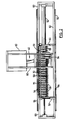
- the springs are inserted into the quilt by the apparatus shown in Figures 1-6.
- the apparatus includes a spring making machine 30 which may be a conventional machine for forming coil springs from wire. Since its sole function is to provide springs for use by the rest of the apparatus, it could be replaced by a reservoir or magazine providing a source of springs, but integration of the spring making step into the apparatus is preferred and is particularly advantageous with the high capacity spring forming machines now becoming available.
- a spring feeding assembly 40 feeds springs delivered by the machine 1 to spring insertion mechanisms 70 mounted on a moving table 50 supported on a machine frame 60 for lateral motion.
- a further laterally movable trolley (not shown) may be located in front of the frame 60, and can serve the dual purposes of preparing the quilt 24 for transfer to the table 50, and supporting a finished spring assembly as it is formed on the table.
- the spring feeding assembly 40 has a chute 42 supported by the frame 60 which delivers successive springs emerging from the machine 30 into a vertical tube 44.
- Each spring 10 delivered into the tube 44 is compressed by a ram 46 of a pneumatic cylinder 48 so as to reduce its height to less than that of a passage 41 extending horizontally forward towards the table 50, so that a plunger 43 may project the compressed spring forwardly into the passage 41.
- the formation and ejection of springs by the machine 30, reciprocation of the ram 46, and movement of the table 50 are synchronized to provide delivery of compressed springs to successive spring insertion mechanisms 70.
- a spring 10 into the passage 41 will result in a spring already in the passage being ejected into a rear end of a channel accumulator tube 72 (see Figures 6A - 6D), or depending on the stroke of the plunger 43, the spring may be ejected directly into the tube 72.
- the table 50 is indexed laterally to align a further assembly 70 with the passage 41. If there is more than one passage 41, the table is indexed a distance corresponding to the number of assemblies 70 being serviced simultaneously.
- a further pass is commenced, preferably with the table being indexed in the opposite direction rather than being returned to an opposite end of its stroke.
- Indexing of the table 50 is performed by a cylinder 52 mounted on the frame 60, in association with limit switches and a brake, to control the indexing movement in known manner.
- the table is supported by rollers 54 engaging rails 56 secured to the frame 60.
- the table 50 In addition to a row of the assemblies 70, mounted at a pitch equal to the lateral pitch of springs in the finished spring assembly, the table 50 also supports a row of pusher arms 58 mounted at a similar pitch on an actuating bar 51 so as to flank each assembly 70.
- the actuating bar is moved first forwardly and then rearwardly by cylinders 53 between each lateral pass of the table 50 so that fingers 55 on the ends of the arms can enter the slits 12 in the quilt 24, and engage a lateral row of intersections 8 to draw the quilt forwardly through a distance equal to the distance between successive intersections 8.
- the fingers ride over the next row of intersections and engage the slits beyond, ready for their next forward stroke.
- fastener applying mechanisms 80 utilized to apply the fastening members 18 and 20.
- Each mechanism 80 has two adjacent applicator guns 82 so that it can apply fasteners to folds of fabric on either side of an assembly 70.
- the guns may either operate simultaneously between every other indexing movement of the table, or preferably the leading gun may be utilized in each direction of movement of the table to ensure that fasteners are applied in folds to each side of each mechanism 70.
- the fasteners are fed from reels 84, and the mechanisms 80 and guns 82 are controlled by control boxes 86.
- Each assembly 70 includes a flattened tube or guide 72 through which compressed springs from the passage 41 are advanced by one spring diameter each time a new spring is inserted into the passage 41, i.e. once for each pass of the table 50.
- portions of the horizontal side walls of the tube are cut away to form openings 71, which reduce the frictional engagement between the tube and the springs and provide clearance for the arms and for fabric gathered on the tubes.
- At a forward end of each tube 72 are pivoted upper and lower arms 74, actuated by small air cylinders 73 between extended ( Figure 6D) and retracted ( Figures 6A-C) positions.
- a pre-prepared quilt 24 (see Figure 7) is placed from the front on the tubes 72, so that a tube enters each tunnel formed by portions of the quilt between zones 4.
- the quilt is pushed as far onto the tubes as possible whilst the arms 58 are raised by cylinders 59 so that its material gathers on the rear portions of the tubes, and only a front edge of the quilt is pulled forward so that the fingers 53 of the arms 58 can engage the frontmost slit in each zone 4.
- a pass of the table 50 is then run without inserting springs into the passages 41 so that the fastening mechanisms may apply initial fastenings to upper and lower folds of the fabric which are formed by opening the arms 74 on each tube 72.
- these fastenings could be applied before placing the quilt on the tubes 72.
- the arms 58 are actuated by the cylinders 53 so as to advance the quilt a further one pitch beyond the ends of the tubes. If the tubes 72 are not preloaded, sufficient passes during which springs are fed should be run to achieve this condition.
- springs are loaded into the passages 42, with the result that springs are ejected from the tubes or guides 72 into the pockets formed by the quilt to the rear of the fastenings applied in the previous pass, and further pockets are formed, by the application of fastenings by the application guns 82, behind the springs during each pass, followed by further advance of the quilt by the arms 58 at the end of each pass.
- the completed portion of the assembly can be supported on the separate trolley previously mentioned, which can move sideways as required with the table 50: the stepping motion of the table will be smoothed out by the flexibility of the spring assembly.
- a row of horns on the trolley may also be used to prepare a quilt for mounting on the tubes 72 and to assist in transferring it to the tubes 72 by aligning the horns, which may be hollow tubes, with the tubes 72.
- the spring forming machine 30 if it is programmable, it may be possible to alter the characteristics of springs inserted into different portions of the assembly, e.g. the side and centre portions of a mattress assembly.
- more than one machine 30 and feed assembly 40 could be provided to service separate insertion mechanisms 70 adjacent different zones of the table 50.
Landscapes
- Engineering & Computer Science (AREA)
- Mechanical Engineering (AREA)
- Mattresses And Other Support Structures For Chairs And Beds (AREA)
- Springs (AREA)
- Sewing Machines And Sewing (AREA)
Claims (15)
- Verfahren zur Herstellung einer Taschenfederanordnung (2), bei dem man zwei Textilstofflagen entlang mehreren parallelen Nahtbereichen (4) zur Bildung eines mehrere parallele Textilstoffschläuche definierenden gesteppten Flächengebildes (24) aneinander befestigt, die so gebildeten Schläuche auf sich in Längsrichtung durch die Schläuche erstreckenden Führungen (72) stützt, Teile des gesteppten Flächengebildes (24) wiederholt an ihrem einen Ende von den Führungen (72) zieht und in jeder Textilstofflage im abgezogenen Teil gebildete Falten zur Bildung von Taschen (14) aus den abgezogenen Teilen des gesteppten Flächengebildes befestigt und vorkomprimierte Schraubenfedern (10) zwischen jedem Ziehen des gesteppten Flächengebildes (24) mit ihren Achsen sowohl senkrecht zu den Achsen der Textilstoffschläuche als auch zur Vorschubrichtung des gesteppten Flächengebildes durch die Führungen (72) führt und in die Taschen (14) freigibt, so daß befestigte Falten im Textilstoff der Schläuche vor und hinter den freigegebenen Federn (10) sie in den Taschen (14) festhalten.
- Verfahren nach Anspruch 1, bei dem voneinander beabstandete Längsschlitze (12) in den Nahtzonen ausgebildet werden, wobei die Schlitze (12) ein Umhüllen der Schläuche durch den Textilstoff gestatten.
- Verfahren nach Anspruch 2, bei dem die Nahtbereiche (4) durch zwei Reihen Nähte (6), die sich zwischen jedem Schlitz (bei 8) schneiden, gebildet werden.
- Vorrichtung zur Herstellung einer Taschenfederanordnung (2), die folgendes umfaßt: zwei Reihen paralleler Führungen (72) zur Aufnahme von in einem gesteppten Flächengebilde (24), das durch Verbindung zweier Textilstofflagen entlang paralleler Bereiche (4) hergestellt ist, definierten Schläuchen um sie herum, einen Mechanismus (58) zum Zurückziehen aufeinanderfolgender Teile des gesteppten Flächengebildes (24) von Enden der Führungen (72), einen Mechanismus (80) zum Anbringen aufeinanderfolgender Befestigungen (18, 20) an in dem Textilstoff der Schläuche der abgezogenen Teile ausgebildeten Falten zur Bildung von Taschen (14), und einen Mechanismus (43) zur Abgabe komprimierter Schraubenfedern (10) durch die Führungen (72) in die Taschen (14) bei ihrer Bildung.
- Vorrichtung nach Anspruch 4, bei der die mehreren parallelen Führungen (72) an einem Tisch (50) angebracht sind, der so montiert ist, daß er eine Bewegung in einer senkrecht zu den Achsen der Führungen (72) verlaufenden Richtung ausführen kann, mit einem Mechanismus (52) zum Weiterschalten des Tisches zur Ausrichtung aufeinanderfolgender Führungen auf den Federabgabemechanismus (43) und auf die Mechanismen (80) zum Anbringen der Befestigungen.
- Vorrichtung nach Anspruch 5, mit einer Federherstellungsmaschine (30), die den Federabgabemechanismus (43) mit Federn (10) versorgt.
- Vorrichtung nach Anspruch 4, 5 oder 6, bei der die Führungen (72) Spreizarmen (74) neben ihren Enden zugeordnet sind, um die Falten an einander gegenüberliegenden Seiten des gesteppten Flächengebildes (24) im Textilstoff auszubilden, wobei die Arme (74) zwischen einer zurückgezogenen Position, die ein Zurückziehen des gesteppten Flächengebildes gestattet, und einer ausgezogenen Position, in der die Falten in einem zurückgezogenen Teil des gesteppten Flächengebildes ausgebildet werden, hin- und herbewegbar sind.
- Vorrichtung nach einem der Ansprüche 4 - 7, bei der es sich bei den Führungen (72) um Schläuche handelt, die in einer gemeinsamen Ebene flachgedrückt sind und bei denen Teile (71) ihrer benachbarten Ränder zur Vergrößerung des Abstands zwischen den Schläuchen (72) und Verringerung der Reibung an den durch sie hindurchgeführten Federn (10) weggeschnitten sind.
- Taschenfederanordnung (2) mit einem gesteppten Flächengebilde (24), das aus zwei zur Bildung mehrerer Textilstoffschläuche entlang mehrerer paralleler Nahtbereiche (4) aneinander befestigten Textilstofflagen besteht, wobei der Textilstoff jeder Lage durch mehrere gleichmäßig voneinander beabstandete Verbindungen (18, 20) entlang jedem Textilstoffschlauch in den Falten befestigt ist, um die Textilstoffschläuche zu einer Gruppierung von Taschen (14) anzuordnen, und einer Schraubenfeder (10), die in jeder Tasche mit ihrer Achse senkrecht zu einer Ebene des gesteppten Flächengebildes (24) auseinandergezogen ist.
- Taschenfederanordnung nach Anspruch 9, bei der das gesteppte Flächengebilde (24) Schlitze (12) in den Nahtbereichen (4) zwischen benachbarten Schläuchen aufweist, wobei die Schlitze (12) Öffnungen (22) zwischen im Textilstoff benachbarter Textilstoffschläuche befestigten Falten bilden.
- Taschenfederanordnung nach Anspruch 10, bei der die Nahtbereiche (4) zwischen benachbarten Schläuchen jeweils zwei Linien von Nähten (6) umfassen, die sich in Längsrichtung des Nahtbereichs (4) erstrecken und sich zwischen jedem Schlitz (12) schneiden, wobei die Schlitze zwischen den Linien von Nähten (6) verlaufen.
- Taschenfederanordnung nach einem der Ansprüche 9 - 11, bei der Federn (10) in verschiedenen Teilen der Anordnung (2) verschiedene Eigenschaften haben.
- Taschenfederanordnung nach einem der Ansprüche 9 - 12, bei der die Falten durch zwei Verbindungen (18, 20), die in einer parallel zu den Federachsen verlaufenden Richtung in einem Abstand voneinander angeordnet sind, der geringer ist als die ausgezogene Länge einer Feder (10) in der Tasche (14), zwischen jeder Feder (10) befestigt sind.
- Gestepptes Flächengebilde (24) zur Herstellung einer Taschenfederanordnung (2), die zwei entlang mehreren parallelen Nahtbereichen (4) zur Bildung mehrerer Textilstoffschläuche aneinander befestigte Textilstofflagen und mehrere gleichmäßig voneinander beabstandete Schlitze (12), die in Längsrichtung der Nahtbereiche (4) zwischen benachbarten Textilstoffschläuchen ausgebildet sind, umfaßt, wobei die Länge der Schlitze (12) eine Befestigung des Textilstoffes der Schläuche neben den Schlitzen in den die Schläuche zu einer Gruppierung von Taschen (14) teilenden Falten gestattet, wobei die Taschen (14) jeweils ausreichend groß sind, eine Schraubenfeder (10), deren Achse senkrecht zu einer Ebene des gesteppten Flächengebildes (24) verläuft, aufzunehmen.
- Gestepptes Flächengebilde nach Anspruch 14, bei dem die Nahtbereiche (4) zwischen benachbarten Schläuchen jeweils zwei Linien von Nähten (6) umfassen, die sich in Längsrichtung des Nahtbereichs (4) erstrecken und sich (bei 8) zwischen jedem Schlitz (12) schneiden, wobei die Schlitze zwischen den Linien der Nähte (6) verlaufen.
Applications Claiming Priority (3)
| Application Number | Priority Date | Filing Date | Title |
|---|---|---|---|
| GB9301927 | 1993-02-01 | ||
| GB939301927A GB9301927D0 (en) | 1993-02-01 | 1993-02-01 | Pocket spring assemblies |
| PCT/CA1994/000055 WO1994018116A1 (en) | 1993-02-01 | 1994-02-01 | Manufacture of pocket spring assemblies |
Publications (2)
| Publication Number | Publication Date |
|---|---|
| EP0694024A1 EP0694024A1 (de) | 1996-01-31 |
| EP0694024B1 true EP0694024B1 (de) | 1999-07-21 |
Family
ID=10729641
Family Applications (1)
| Application Number | Title | Priority Date | Filing Date |
|---|---|---|---|
| EP94905640A Expired - Lifetime EP0694024B1 (de) | 1993-02-01 | 1994-02-01 | Herstellung von taschenfederaufbauten |
Country Status (10)
| Country | Link |
|---|---|
| US (1) | US5699998A (de) |
| EP (1) | EP0694024B1 (de) |
| AU (2) | AU5968194A (de) |
| CA (1) | CA2155212C (de) |
| DE (1) | DE69419603T2 (de) |
| DK (1) | DK0694024T3 (de) |
| ES (1) | ES2136728T3 (de) |
| GB (1) | GB9301927D0 (de) |
| NZ (1) | NZ261095A (de) |
| WO (1) | WO1994018116A1 (de) |
Families Citing this family (35)
| Publication number | Priority date | Publication date | Assignee | Title |
|---|---|---|---|---|
| US6029957A (en) * | 1994-02-01 | 2000-02-29 | Furniture Row Technologies, Llc | Manufacture of pocket spring assemblies |
| US5444905A (en) * | 1994-03-14 | 1995-08-29 | Simmons Company | Apparatus for manufacturing mattresses and box springs |
| DE4435771A1 (de) * | 1994-10-06 | 1996-04-11 | Recticel Nv | Vorrichtung zur Herstellung eines Taschenfederkernes |
| AU2377095A (en) * | 1995-03-05 | 1996-09-23 | New Technology I Lidkoping Ab | Apparatus for the manufacture of innerspring constructions |
| US6315275B1 (en) | 1995-09-18 | 2001-11-13 | Furniture Row Technologies, Llc | Pocket spring assembly and methods |
| US6159319A (en) * | 1996-04-29 | 2000-12-12 | L&P Property Management Company | Method and apparatus for forming pocketed coil spring mattresses |
| US5885407A (en) * | 1996-04-29 | 1999-03-23 | Mossbeck; Niels S. | Method and apparatus for forming pocket spring coil mattresses |
| US5868383A (en) * | 1997-03-27 | 1999-02-09 | L&P Property Management Company | Multiple rate coil spring assembly |
| GB9806778D0 (en) * | 1998-03-31 | 1998-05-27 | Elson & Robbins Limited | Apparatus for the production of pocketed coil springs |
| GB9813805D0 (en) * | 1998-06-27 | 1998-08-26 | Harrison Bedding Limited A | Spring units |
| US6021627A (en) * | 1998-08-24 | 2000-02-08 | L & P Property Management Company | Manufacture of pocketed compound nested coil springs |
| CZ2001186A3 (cs) | 1998-08-25 | 2002-03-13 | L & P Property Management Company | Způsob výroby balených pruľinových jednotek |
| SE517533C2 (sv) * | 1999-03-25 | 2002-06-18 | Stjernfjaedrar Ab | Resårmadrass omfattande ett flertal sammankopplade spiralfjädrar, metod för tillverkande av en resårmadrass samt anordning för förspännande av spiralfjädrar |
| US6834477B2 (en) * | 1999-04-16 | 2004-12-28 | Spuhl Ag | Method and system for forming strings of pocketed coil springs with traction mechanism |
| US6499275B1 (en) | 1999-04-16 | 2002-12-31 | Spuhl Ag St. Gallen | Method and system for forming strings of pocketed coil springs |
| US6336305B1 (en) | 1999-04-16 | 2002-01-08 | Spuhl Ag St. Gallen | System for forming strings of pocketed coil springs |
| US6591436B2 (en) | 1999-04-16 | 2003-07-15 | Spuhl Ag St. Gallen | Side seam pocketed coil springs |
| US6256820B1 (en) | 2000-02-09 | 2001-07-10 | L&P Property Management Company | Multilayered pocketed bedding or seating product |
| US6684435B1 (en) | 2002-10-24 | 2004-02-03 | L&P Property Management Company | Method of manufacturing bedding or seating product having coaxial coil springs |
| US6862763B2 (en) | 2002-12-02 | 2005-03-08 | L&P Property Management Company | Pocketed bedding or seating product having pockets of differing heights |
| US6829798B2 (en) | 2003-01-08 | 2004-12-14 | L&P Property Management Company | Low density pocketed spring assembly and method of manufacture |
| US6813791B2 (en) | 2003-03-04 | 2004-11-09 | L&P Property Management Company | Posturized pocketed bedding or seating product having pockets of differing heights |
| SE527152C2 (sv) * | 2003-12-12 | 2006-01-10 | Stjernfjaedrar Ab | Separerad pocketmadrass med uppskurna strängar, samt metod och anordning för dess tillverkning |
| SE526926C2 (sv) * | 2004-04-26 | 2005-11-22 | Stjernfjaedrar Ab | Ändseparerad pocketmadrass samt metod och anordning för tillverkande av densamma |
| DE202005002906U1 (de) * | 2005-02-22 | 2005-05-04 | Spiroplex GmbH i.G. | Polsterfedereinrichtung |
| GB0519009D0 (en) * | 2005-09-17 | 2005-10-26 | Harrison Bedding Ltd | Pocketted spring units |
| US9161634B2 (en) * | 2007-10-29 | 2015-10-20 | Dreamwell, Ltd. | Asymmetrical combined cylindrical and conical springs |
| US20110148018A1 (en) * | 2007-10-29 | 2011-06-23 | Dreamwell, Ltd. | Asymmetrical combined cylindrical and conical springs |
| AU2011201807B2 (en) * | 2010-04-28 | 2016-05-19 | Mantzis Holdings Pty Ltd. | Mattress core |
| CA2817294C (en) | 2010-11-09 | 2019-02-12 | Dreamwell, Ltd. | Spring coils for innerspring assemblies and methods of manufacture |
| CN102218489A (zh) * | 2011-03-25 | 2011-10-19 | 谭治铭 | 改进型多绕制机床网弹簧生产装置 |
| PL2565152T3 (pl) * | 2011-08-30 | 2014-11-28 | Spuehl Ag | Urządzenie do tworzenia rękawa z materiału kieszeni i sposób wytwarzania rzędu sprężyn kieszeniowych |
| TR201801598T1 (tr) | 2015-08-03 | 2018-04-24 | Bedgear Llc | Özelleşti̇ri̇lebi̇li̇r yatak şi̇ltesi̇ |
| CN112537083A (zh) * | 2020-12-05 | 2021-03-23 | 嘉兴腾森五金有限公司 | 一种高效的袋装弹簧自动生产装置 |
| CN113800462B (zh) * | 2021-08-19 | 2023-01-03 | 运时通(中国)家具有限公司 | 弹性床垫的筒袋装弹簧装配设备 |
Family Cites Families (59)
| Publication number | Priority date | Publication date | Assignee | Title |
|---|---|---|---|---|
| US1313234A (en) * | 1919-08-12 | john g | ||
| US1370533A (en) * | 1921-03-08 | Method of and machine fob | ||
| US685160A (en) * | 1900-09-01 | 1901-10-22 | James Marshall | Mattress. |
| US698529A (en) * | 1901-06-22 | 1902-04-29 | James Marshall | Mattress. |
| US1270840A (en) * | 1915-08-02 | 1918-07-02 | Foster Brothers Mfg Co | Cushion-seat and mattress. |
| US1253272A (en) * | 1915-09-13 | 1918-01-15 | Fred A Nachman | Cushion construction. |
| US1287663A (en) * | 1917-06-07 | 1918-12-17 | Foster Brothers Mfg Co | Covered-spring structure. |
| US1247971A (en) * | 1917-07-14 | 1917-11-27 | Phillip Krakauer | Spring-pad and method of making same. |
| US1284384A (en) * | 1918-05-15 | 1918-11-12 | William Lewis | Spring-mattress. |
| US1466617A (en) * | 1919-11-21 | 1923-08-28 | Foster Brothers Mfg Co | Covered-spring structure |
| US1455847A (en) * | 1920-02-24 | 1923-05-22 | Charles C Meutsch | Mattress, cushion, and seat |
| US1406051A (en) * | 1920-04-26 | 1922-02-07 | Samuel S Marcus | Spring pad |
| US1445416A (en) * | 1921-03-21 | 1923-02-13 | Frederick C Genge | Filling machine |
| US1465766A (en) * | 1922-06-15 | 1923-08-21 | Krakauer Phillip | Spring pad |
| US1560588A (en) * | 1924-02-21 | 1925-11-10 | Lewis William | Spring cushion |
| US1813993A (en) * | 1926-02-26 | 1931-07-14 | Simmons Co | Machine for and method of assembling springs |
| US1724681A (en) * | 1926-08-18 | 1929-08-13 | Roseman Leo | Automatic work-starting mechanism for sewing machines |
| US1720480A (en) * | 1927-03-09 | 1929-07-09 | Karpen & Bros S | Cushion structure and manufacture |
| US1685851A (en) * | 1927-05-09 | 1928-10-02 | James L Macinerney | Machine for placing springs in fabric pockets |
| US1759050A (en) * | 1927-05-31 | 1930-05-20 | Simmons Co | Method of and machine for assembling springs |
| US1861429A (en) * | 1929-05-17 | 1932-05-31 | Bernard R Schneider | Machine for inclosing metallic coiled springs |
| US1867872A (en) * | 1929-10-05 | 1932-07-19 | Edward L Bronstien | Box spring mechanism |
| US1950186A (en) * | 1931-03-18 | 1934-03-06 | Karpen & Bros S | Coil spring inserting machine |
| GB373813A (en) * | 1931-06-26 | 1932-06-02 | Julius Spuhl | A machine for the insertion of upholstery springs into covers or pockets |
| US2048979A (en) * | 1934-03-24 | 1936-07-28 | Burton Dixie Corp | Spring cushion assembly |
| US2032510A (en) * | 1934-03-28 | 1936-03-03 | Spuhl Julius | Machine for the manufacture of pocket bands containing upholstery springs |
| US2320153A (en) * | 1940-10-17 | 1943-05-25 | Reynolds Spring Co | Spring construction |
| US2430098A (en) * | 1944-03-10 | 1947-11-04 | William Rhodes Ltd | Pocket spring surfaces |
| US2647671A (en) * | 1947-12-15 | 1953-08-04 | James L Mcinerney | Spring loading machine |
| US2615180A (en) * | 1949-05-07 | 1952-10-28 | Simmons Co | Spring assembly |
| US2862214A (en) * | 1956-10-04 | 1958-12-02 | Marspring Corp | Cushion or mattress construction and method of manufacture |
| US3099021A (en) * | 1957-05-28 | 1963-07-30 | Englander Co Inc | Foam mattress |
| US2983236A (en) * | 1958-03-24 | 1961-05-09 | Marspring Corp | Apparatus for making lengths of fabric-pocketed spring coils |
| US2934219A (en) * | 1958-08-15 | 1960-04-26 | Simmons Co | Mattress handling mechanism |
| US3193136A (en) * | 1959-10-22 | 1965-07-06 | Simmons Co | Coil feeding apparatus |
| US3046574A (en) * | 1959-12-23 | 1962-07-31 | Superior Bedding Company | Mattress construction |
| US3168792A (en) * | 1963-06-28 | 1965-02-09 | Simmons Co | Method and apparatus for making spring assemblies |
| US3230558A (en) * | 1963-06-28 | 1966-01-25 | Simmons Co | Spring assembly |
| CA913815A (en) * | 1969-05-30 | 1972-10-31 | Convexco Limited | Spring upholstery assembly |
| US3668816A (en) * | 1970-07-10 | 1972-06-13 | Mildred B Thompson | Method and apparatus for constructing fabric enclosed springs |
| US3789495A (en) * | 1972-01-18 | 1974-02-05 | Simmons Co | Method for manufacturing box spring |
| US3869739A (en) * | 1973-11-16 | 1975-03-11 | Marspring Corp | Cushion or mattress construction |
| US4439977A (en) * | 1977-05-05 | 1984-04-03 | Simmons U.S.A. Corporation | Method and apparatus for making a series of pocketed coil springs |
| US4234983A (en) * | 1978-10-02 | 1980-11-25 | Simmons Company | Thermally welded spring pockets |
| US4234984A (en) * | 1979-03-19 | 1980-11-25 | Simmons Company | Pocketed spring assembly |
| US4401501A (en) * | 1981-03-11 | 1983-08-30 | Simmons Usa Corporation | Apparatus for making assemblies of pocketed springs |
| US4451946A (en) * | 1981-11-20 | 1984-06-05 | Simmons U.S.A. Corporation | Pocketed spring assembly |
| US4523344A (en) * | 1982-09-17 | 1985-06-18 | Simmons U.S.A. Corporation | Independent block assembly of springs |
| US4485506A (en) * | 1983-04-07 | 1984-12-04 | Simmons U.S.A. Corporation | Coil spring construction |
| US4491491A (en) * | 1983-11-02 | 1985-01-01 | Simmons U.S.A. Corporation | Ultrasonic separation apparatus |
| US4566926A (en) * | 1984-03-09 | 1986-01-28 | Simmons U.S.A. Corporation | Method and apparatus for manufacturing innerspring constructions |
| US4578834A (en) * | 1984-03-09 | 1986-04-01 | Simmons U.S.A. Corporation | Innerspring construction |
| US4565046A (en) * | 1984-12-24 | 1986-01-21 | Simmons U.S.A. Corporation | Apparatus for manufacturing pocketed coil springs |
| US4679266A (en) * | 1986-02-18 | 1987-07-14 | Eugene Kraft | Varying firmness mattress |
| US4986518A (en) * | 1988-06-13 | 1991-01-22 | Simmons U.S.A. Corporation | Pocketed coil strings having a flat overlap side seam |
| US4854023A (en) * | 1988-06-13 | 1989-08-08 | Simmons U.S.A. Corporation | Method for providing pocketed coil strings having a flat overlap side seam |
| US4895352A (en) * | 1989-01-09 | 1990-01-23 | Simmons Company | Mattress or cushion spring array |
| GB8923528D0 (en) * | 1989-10-18 | 1989-12-06 | Rogers Paul | Spring unit assembly |
| DE4026502C1 (en) * | 1990-08-22 | 1991-06-06 | Schlaraffia-Werke Hueser Gmbh & Co Kg, 4630 Bochum, De | Pocket spring core - has parallel chains of pocketed springs with insert slits extending over half chain height |
-
1993
- 1993-02-01 GB GB939301927A patent/GB9301927D0/en active Pending
-
1994
- 1994-02-01 DK DK94905640T patent/DK0694024T3/da active
- 1994-02-01 US US08/500,904 patent/US5699998A/en not_active Expired - Fee Related
- 1994-02-01 WO PCT/CA1994/000055 patent/WO1994018116A1/en not_active Ceased
- 1994-02-01 ES ES94905640T patent/ES2136728T3/es not_active Expired - Lifetime
- 1994-02-01 AU AU59681/94A patent/AU5968194A/en not_active Abandoned
- 1994-02-01 CA CA002155212A patent/CA2155212C/en not_active Expired - Fee Related
- 1994-02-01 DE DE69419603T patent/DE69419603T2/de not_active Expired - Fee Related
- 1994-02-01 EP EP94905640A patent/EP0694024B1/de not_active Expired - Lifetime
- 1994-02-01 NZ NZ261095A patent/NZ261095A/en unknown
-
1998
- 1998-04-06 AU AU60660/98A patent/AU6066098A/en not_active Abandoned
Also Published As
| Publication number | Publication date |
|---|---|
| NZ261095A (en) | 1997-04-24 |
| AU5968194A (en) | 1994-08-29 |
| GB9301927D0 (en) | 1993-03-17 |
| CA2155212C (en) | 2001-12-18 |
| EP0694024A1 (de) | 1996-01-31 |
| US5699998A (en) | 1997-12-23 |
| WO1994018116A1 (en) | 1994-08-18 |
| DE69419603D1 (de) | 1999-08-26 |
| ES2136728T3 (es) | 1999-12-01 |
| CA2155212A1 (en) | 1994-08-18 |
| DK0694024T3 (da) | 2000-02-28 |
| AU6066098A (en) | 1998-06-18 |
| DE69419603T2 (de) | 2000-02-10 |
Similar Documents
| Publication | Publication Date | Title |
|---|---|---|
| EP0694024B1 (de) | Herstellung von taschenfederaufbauten | |
| US6029957A (en) | Manufacture of pocket spring assemblies | |
| EP0311830B1 (de) | Verfahren und Vorrichtung zum gruppenweisen Verpacken von Einzelpackungen | |
| CA2626919C (en) | Pocketed spring units | |
| US6467240B2 (en) | Pocket spring assembly and methods | |
| US3668816A (en) | Method and apparatus for constructing fabric enclosed springs | |
| DE69508936T2 (de) | Vorrichtung und verfahren zum anbringen von tuftinggarnen auf einen tuftinggarnträger | |
| DE69626008T2 (de) | Verfahren und vorrichtung zur montrage einer spiralfedereinheit | |
| CZ288277B6 (en) | Brush making machine | |
| US3937158A (en) | Method and means of tufting | |
| CH505245A (de) | Verfahren zur Herstellung von ein- oder mehrfarbigen Flor aufweisenden Textilien, insbesondere Florteppichen | |
| DE2353884A1 (de) | Tuftmaschine und tuftverfahren | |
| US3937156A (en) | Method and means of tufting | |
| DE3221620A1 (de) | Vorrichtung zum anbringen von komponenten | |
| US3937643A (en) | Method and means of tufting | |
| DE2139023A1 (de) | Verfahren und Vorrichtung zur Her stellung von mit synthetischen Fasern gefüllten oder gestopften Artikeln | |
| DE3719823C1 (de) | Verfahren und Vorrichtung zur Herstellung von Borstenwaren sowie Anwendung des Verfahrens fuer Geraete aehnlichen Aufbaus | |
| DE60312761T2 (de) | Verfahren und Vorrichtung zur Beschickung von chirurgischen Nadeln in chirurgische Nahtpackungen | |
| US3318497A (en) | Loop-making apparatus and method | |
| US3110427A (en) | Pleater structure | |
| JPH03119167A (ja) | パイルファブリックの製造装置と方法 | |
| EP0983207A1 (de) | Verfahren und vorrichtung zur herstellung von taschenfederkernen | |
| DE1785465C3 (de) | Vorrichtung zur Erzeugung und Zuführung von Faserbüscheln bei der Herstellung eines gemusterten Florteppichs o.dgl |
Legal Events
| Date | Code | Title | Description |
|---|---|---|---|
| PUAI | Public reference made under article 153(3) epc to a published international application that has entered the european phase |
Free format text: ORIGINAL CODE: 0009012 |
|
| 17P | Request for examination filed |
Effective date: 19950901 |
|
| AK | Designated contracting states |
Kind code of ref document: A1 Designated state(s): BE DE DK ES FR GB NL SE |
|
| RBV | Designated contracting states (corrected) |
Designated state(s): BE DE DK ES FR GB NL SE |
|
| 17Q | First examination report despatched |
Effective date: 19961122 |
|
| GRAG | Despatch of communication of intention to grant |
Free format text: ORIGINAL CODE: EPIDOS AGRA |
|
| GRAG | Despatch of communication of intention to grant |
Free format text: ORIGINAL CODE: EPIDOS AGRA |
|
| GRAG | Despatch of communication of intention to grant |
Free format text: ORIGINAL CODE: EPIDOS AGRA |
|
| GRAG | Despatch of communication of intention to grant |
Free format text: ORIGINAL CODE: EPIDOS AGRA |
|
| GRAH | Despatch of communication of intention to grant a patent |
Free format text: ORIGINAL CODE: EPIDOS IGRA |
|
| GRAH | Despatch of communication of intention to grant a patent |
Free format text: ORIGINAL CODE: EPIDOS IGRA |
|
| GRAA | (expected) grant |
Free format text: ORIGINAL CODE: 0009210 |
|
| AK | Designated contracting states |
Kind code of ref document: B1 Designated state(s): BE DE DK ES FR GB NL SE |
|
| REF | Corresponds to: |
Ref document number: 69419603 Country of ref document: DE Date of ref document: 19990826 |
|
| ET | Fr: translation filed | ||
| REG | Reference to a national code |
Ref country code: ES Ref legal event code: FG2A Ref document number: 2136728 Country of ref document: ES Kind code of ref document: T3 |
|
| REG | Reference to a national code |
Ref country code: DK Ref legal event code: T3 |
|
| RAP2 | Party data changed (patent owner data changed or rights of a patent transferred) |
Owner name: FURNITURE ROW TECHNOLOGIES, LLC |
|
| PLBE | No opposition filed within time limit |
Free format text: ORIGINAL CODE: 0009261 |
|
| STAA | Information on the status of an ep patent application or granted ep patent |
Free format text: STATUS: NO OPPOSITION FILED WITHIN TIME LIMIT |
|
| NLS | Nl: assignments of ep-patents |
Owner name: FURNITURE ROW TECHNOLOGIES, LLC |
|
| NLT2 | Nl: modifications (of names), taken from the european patent patent bulletin |
Owner name: FURNITURE ROW TECHNOLOGIES, LLC |
|
| 26N | No opposition filed | ||
| REG | Reference to a national code |
Ref country code: GB Ref legal event code: 732E |
|
| REG | Reference to a national code |
Ref country code: GB Ref legal event code: IF02 |
|
| PGFP | Annual fee paid to national office [announced via postgrant information from national office to epo] |
Ref country code: NL Payment date: 20050116 Year of fee payment: 12 |
|
| PGFP | Annual fee paid to national office [announced via postgrant information from national office to epo] |
Ref country code: GB Payment date: 20050126 Year of fee payment: 12 |
|
| PGFP | Annual fee paid to national office [announced via postgrant information from national office to epo] |
Ref country code: FR Payment date: 20050217 Year of fee payment: 12 |
|
| PGFP | Annual fee paid to national office [announced via postgrant information from national office to epo] |
Ref country code: SE Payment date: 20050222 Year of fee payment: 12 |
|
| PGFP | Annual fee paid to national office [announced via postgrant information from national office to epo] |
Ref country code: DK Payment date: 20050223 Year of fee payment: 12 |
|
| PGFP | Annual fee paid to national office [announced via postgrant information from national office to epo] |
Ref country code: ES Payment date: 20050309 Year of fee payment: 12 |
|
| PGFP | Annual fee paid to national office [announced via postgrant information from national office to epo] |
Ref country code: DE Payment date: 20050331 Year of fee payment: 12 |
|
| PGFP | Annual fee paid to national office [announced via postgrant information from national office to epo] |
Ref country code: BE Payment date: 20050414 Year of fee payment: 12 |
|
| PG25 | Lapsed in a contracting state [announced via postgrant information from national office to epo] |
Ref country code: GB Free format text: LAPSE BECAUSE OF NON-PAYMENT OF DUE FEES Effective date: 20060201 |
|
| PG25 | Lapsed in a contracting state [announced via postgrant information from national office to epo] |
Ref country code: SE Free format text: LAPSE BECAUSE OF NON-PAYMENT OF DUE FEES Effective date: 20060202 Ref country code: ES Free format text: LAPSE BECAUSE OF NON-PAYMENT OF DUE FEES Effective date: 20060202 |
|
| PG25 | Lapsed in a contracting state [announced via postgrant information from national office to epo] |
Ref country code: DK Free format text: LAPSE BECAUSE OF NON-PAYMENT OF DUE FEES Effective date: 20060228 Ref country code: BE Free format text: LAPSE BECAUSE OF NON-PAYMENT OF DUE FEES Effective date: 20060228 |
|
| PG25 | Lapsed in a contracting state [announced via postgrant information from national office to epo] |
Ref country code: NL Free format text: LAPSE BECAUSE OF NON-PAYMENT OF DUE FEES Effective date: 20060901 Ref country code: DE Free format text: LAPSE BECAUSE OF NON-PAYMENT OF DUE FEES Effective date: 20060901 |
|
| REG | Reference to a national code |
Ref country code: DK Ref legal event code: EBP |
|
| EUG | Se: european patent has lapsed | ||
| GBPC | Gb: european patent ceased through non-payment of renewal fee |
Effective date: 20060201 |
|
| NLV4 | Nl: lapsed or anulled due to non-payment of the annual fee |
Effective date: 20060901 |
|
| REG | Reference to a national code |
Ref country code: FR Ref legal event code: ST Effective date: 20061031 |
|
| REG | Reference to a national code |
Ref country code: ES Ref legal event code: FD2A Effective date: 20060202 |
|
| BERE | Be: lapsed |
Owner name: *FURNITURE ROW TECHNOLOGIES LLC Effective date: 20060228 |
|
| PG25 | Lapsed in a contracting state [announced via postgrant information from national office to epo] |
Ref country code: FR Free format text: LAPSE BECAUSE OF NON-PAYMENT OF DUE FEES Effective date: 20060228 |