EP0695606A1 - Fuzzy-Steuerungs-Prozess- und Einrichtung zur Positionierung und raschen Dämpfung mechanischer Schwingungen - Google Patents
Fuzzy-Steuerungs-Prozess- und Einrichtung zur Positionierung und raschen Dämpfung mechanischer Schwingungen Download PDFInfo
- Publication number
- EP0695606A1 EP0695606A1 EP94830372A EP94830372A EP0695606A1 EP 0695606 A1 EP0695606 A1 EP 0695606A1 EP 94830372 A EP94830372 A EP 94830372A EP 94830372 A EP94830372 A EP 94830372A EP 0695606 A1 EP0695606 A1 EP 0695606A1
- Authority
- EP
- European Patent Office
- Prior art keywords
- fuzzy
- derivative
- error
- position error
- fuzzy control
- Prior art date
- Legal status (The legal status is an assumption and is not a legal conclusion. Google has not performed a legal analysis and makes no representation as to the accuracy of the status listed.)
- Withdrawn
Links
Images


Classifications
-
- G—PHYSICS
- G05—CONTROLLING; REGULATING
- G05D—SYSTEMS FOR CONTROLLING OR REGULATING NON-ELECTRIC VARIABLES
- G05D19/00—Control of mechanical oscillations, e.g. of amplitude, of frequency, of phase
- G05D19/02—Control of mechanical oscillations, e.g. of amplitude, of frequency, of phase characterised by the use of electric means
-
- B—PERFORMING OPERATIONS; TRANSPORTING
- B25—HAND TOOLS; PORTABLE POWER-DRIVEN TOOLS; MANIPULATORS
- B25J—MANIPULATORS; CHAMBERS PROVIDED WITH MANIPULATION DEVICES
- B25J9/00—Program-controlled manipulators
- B25J9/16—Program controls
- B25J9/1602—Program controls characterised by the control system, structure, architecture
- B25J9/161—Hardware, e.g. neural networks, fuzzy logic, interfaces, processor
-
- G—PHYSICS
- G05—CONTROLLING; REGULATING
- G05B—CONTROL OR REGULATING SYSTEMS IN GENERAL; FUNCTIONAL ELEMENTS OF SUCH SYSTEMS; MONITORING OR TESTING ARRANGEMENTS FOR SUCH SYSTEMS OR ELEMENTS
- G05B2219/00—Program-control systems
- G05B2219/30—Nc systems
- G05B2219/34—Director, elements to supervisory
- G05B2219/34065—Fuzzy logic, controller
-
- G—PHYSICS
- G05—CONTROLLING; REGULATING
- G05B—CONTROL OR REGULATING SYSTEMS IN GENERAL; FUNCTIONAL ELEMENTS OF SUCH SYSTEMS; MONITORING OR TESTING ARRANGEMENTS FOR SUCH SYSTEMS OR ELEMENTS
- G05B2219/00—Program-control systems
- G05B2219/30—Nc systems
- G05B2219/39—Robotics, robotics to robotics hand
- G05B2219/39195—Control, avoid oscillation, vibration due to low rigidity
-
- G—PHYSICS
- G05—CONTROLLING; REGULATING
- G05B—CONTROL OR REGULATING SYSTEMS IN GENERAL; FUNCTIONAL ELEMENTS OF SUCH SYSTEMS; MONITORING OR TESTING ARRANGEMENTS FOR SUCH SYSTEMS OR ELEMENTS
- G05B2219/00—Program-control systems
- G05B2219/30—Nc systems
- G05B2219/40—Robotics, robotics mapping to robotics vision
- G05B2219/40533—Generate derivative, change of vibration error
-
- G—PHYSICS
- G05—CONTROLLING; REGULATING
- G05B—CONTROL OR REGULATING SYSTEMS IN GENERAL; FUNCTIONAL ELEMENTS OF SUCH SYSTEMS; MONITORING OR TESTING ARRANGEMENTS FOR SUCH SYSTEMS OR ELEMENTS
- G05B2219/00—Program-control systems
- G05B2219/30—Nc systems
- G05B2219/40—Robotics, robotics mapping to robotics vision
- G05B2219/40534—Generate derivative, change of position error
Definitions
- the present invention relates to a fuzzy control process and device for positioning and quickly damping mechanical oscillations.
- Figure 1 illustrates a known system of the PID (proportional-integral-derivative) type for controlling a flexible arm.
- the reference numeral 1 designates a flexible arm that is driven by a motor unit 2.
- Two sensors are associated with the flexible arm 1: a first sensor for detecting the arm position, typically constituted by a potentiometer 3, and a second sensor, typically constituted by a piezoelectric sensor 4, for measuring the variation in the deformation of the arm 1 (i.e. its oscillations).
- the value v measured by the sensor 4 is sent to a first comparator 5 suitable to generate an oscillation error signal E v from the comparison between the oscillation value v measured by the sensor 4 and a reference value v ref .
- the value y of the angular position of the arm 1, measured by the position sensor 3, is instead sent to a second comparator 6 suitable to generate a position error signal E y from the comparison between the value of the angular position y measured by the sensor 3 and a reference value y ref .
- Both reference signals are equal to zero, since oscillations and angular movements of the flexible arm 1 are to be avoided.
- the position error signal E y is sent to an integrator 7 and to a derivative circuit 8.
- the error signal E y , the output of the derivative circuit 8, i.e. its derivative dE y /dt of the error signal, and the output of the integrator 7, i.e. the integral ⁇ E y dt, are sent to a controller 9 of the known type.
- the controller 9 also receives the oscillation error signal E v .
- the controller 9 is suitable to generate a control signal u on the basis of the values of the errors E v , E y , of the derivative dE y /dt, and of the integral ⁇ E y dt; said control signal u is sent to the motor unit 2 which is in turn suitable to drive the flexible arm 1.
- u(k) k p ⁇ E y (k) + k d ⁇ [(E y (k) - E y (k-1))/T]+T/k i ⁇ E y (k)+k v ⁇ E v
- (u)k is the output of the controller 9
- T is the sampling interval (the time elapsing between the acquisition of the input values and the generation of the output values)
- k p is the parameter of the error signal E y
- k d is the parameter of the derivative dE y /dt
- k i is the parameter of the integral ⁇ E y dt
- k v is the parameter of the error E v .
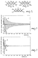
- Figure 2 illustrates the output of the system controlled with an above described controller.
- FIG 2 shows the output of the conventional PID system without vibration control.
- Curve A plots the trend of the vibrations, measured by the sensor 4, whereas curve B plots the trend of angular motions, i.e. of position, measured by the sensor 3.
- the reference values is zero.
- the vibration curve A the system has vibrations even after 1000 samples have been taken (4 s).
- Figure 3 shows the output of the conventional PID system with vibration control. As clearly shown by a comparison with figure 2, the vibrations decrease considerably already after 300 samples have been taken (1.2 seconds). However, the vibrations persist even after 1000 samples have been taken.
- Figures 4 and 5 plot the corresponding outputs of figures 2 and 3, with the difference that a weight is placed on the tip of the rod of the mechanical arm 1. The other parameters remain the same. As shown by figure 4, where there is no vibration control the vibrations are even stronger than in figure 2. Figure 5 shows that where vibration control is present, the vibrations decrease but their presence is nonetheless considerable.
- a principal aim of the present invention is to provide a fuzzy control process for positioning and quickly damping mechanical oscillations that can perform both position control and dynamic damping of oscillations.
- an object of the present invention is to provide a process that can perform robust control.
- Another object of the present invention is to provide a process that is faster and more efficient than conventional systems.
- Another object of the present invention is to provide a process that is simpler than known systems.
- Another object of the present invention is to provide a process that is highly reliable, relatively easy to manufacture, and at low costs.
- a fuzzy control process for positioning and quickly damping mechanical oscillations that comprises the following steps: measuring a value of the position of at least one mechanical element; generating a position error from the comparison between said position value and a first reference value; measuring a value of the deformation of said at least one mechanical element; generating a vibration error from the comparison between said deformation value and a second reference value; generating the derivative of said position error; characterized in that it comprises the additional steps of: generating the derivative of said vibration error; applying a fuzzy control to said position error, to said vibration error, to said derivative of said position error, and to said derivative of said vibration error, so as to generate a control signal suitable to drive means for actuating said at least one mechanical element.
- Figure 6 illustrates the device for embodying the present invention.
- the device according to the present invention includes a flexible arm 1 which is driven by a motor unit 2.
- An oscillation sensor 4 and a position sensor 3 are associated with the arm 1.
- the signal y measured by the position sensor 3 is sent to the comparator 6, which is suitable to generate a position error signal E y from the comparison between the signal y and a reference signal y ref .
- the signal v measured by the sensor 4 is sent to a second comparator 5 which is suitable to generate a vibration error signal from the comparison between the signal v and a reference signal V ref .
- the reference values are normally set to zero.
- the vibration error E v is sent to a derivative circuit 13 suitable to calculate the derivative dE v /dt of said error.
- the derivative circuit 13 determines the variation of the error E v from the comparison of the values of E v at two successive instants E v (t)-E v (t-1) .
- the error E v and its derivative dE v /dt are then sent to a first fuzzy vibration controller 10 which is part of the fuzzy control means of the device according to the present invention.
- the position error E y is sent to a derivative circuit 14 which is suitable to calculate the derivative dE y /dt of said error.
- the derivative circuit 14 determines the variation of the error E y from the comparison of the values of E y in two successive instants E y (t)-E y (t-1) .
- the error E y and its derivative dE y /dt are then sent to a second fuzzy position controller 11 which is also part of the fuzzy control means of the device according to the present invention.
- the fuzzy controllers 10 and 11 respectively have outputs u1 and u2. Said output signals are added at an adder node 12 so as to obtain a control signal u which is sent to amplifier means 9.
- the amplifier means 9 convert the control signal u into a form that is suitable to drive the means for actuating the arm 1, i.e. the motor unit 2.
- the fuzzy vibration controller 10 comprises memory means suitable to store membership functions for the input fuzzy variables: for the vibration error signal E v and for its derivative dE v /dt.
- the fuzzy position controller 11 also comprises respective memory means for storing membership functions defined for the input fuzzy variables: for the position error E y and for its derivative dE y /dt.
- the fuzzy sets for the fuzzy variable E v have been defined as N - Negative, NM - Negative Medium, Z - Zero, PM - Positive Medium, P - Positive.
- a term set for the derivative dE v /dt has been developed in a manner similar to the term set for the vibration error E v .
- the fuzzy sets are identical to those of the error E v (N, NM, Z, PM, P).
- a set of fuzzy rules is stored in the memory means of the fuzzy controllers, and the data measured in input to the controllers and the related membership functions are applied to these rules.
- the fuzzy rules are developed from the technical knowledge available on the system: the experience of technicians and/or characteristic equations.
- the table is to be interpreted as follows. With reference to the first row and the first column, for the error E y one obtains: IF E y IS N AND dE y /dt IS N THEN u2 IS N With reference to the third column and the second row, one obtains: IF E y IS NM AND dE y /dt IS Z THEN u2 IS NM
- the fuzzy inference occurs in the inference means of the controllers 10 and 11 in the manner described hereinafter.
- weight functions which identify some particularly indicative values are determined.
- One of these weight functions is the function ⁇ , which indicates the extent to which the input propositions (A1, B1) match the stored premises (A, B).
- the second weight function is ⁇ i , which indicates the extent of the "general resemblance" of the IF part of a rule.
- MAX/DOT As far as this subject is concerned, two different inference methods are generally considered: MAX/DOT and MAX/MIN. Essentially, both methods act by modifying the membership functions of the consequent by means of a threshold value supplied by the antecedent.
- the MAX/MIN method acts by clipping the membership functions related to the consequent. As regards the input values, one uses the corresponding lower (threshold) membership value with which the membership function of the output is clipped. In practice, the membership function in output will have no value higher than the threshold value.
- the MAX/DOT method instead acts by modifying the membership functions of the right part (the consequent), so that the membership function of the output is "compressed", while however trying to maintain its original shape as much as possible.
- fuzzy control it is possible to simplify the calculation of the weights ⁇ . It is in fact possible to considerably reduce the amount of calculation by assuming that one is dealing with a degenerate case of fuzzy calculus in which the input variables are not fuzzy sets (ambiguous values) but are variables which generally originate from sensors and are thus definite numeric values.
- the input data are not fuzzy sets but crisp values.
- the weights thus computed are used for computation on the consequent of the fuzzy inference (i.e. on the fuzzy rules).
- the weights are calculated by the calculation means of the fuzzy controllers 10 and 11.
- the outputs of the fuzzy controllers 10 and 11 must be physical values u1 and u2.
- the outputs of the fuzzy controllers 10 and 11 must be physical values u1 and u2.
- the inference has been performed on the right part of the fuzzy rules, one obtains a fuzzy set of the output value u1 or u2; it is accordingly necessary to defuzzify, i.e. to extract a definite numeric value of u1 and u2 from the calculated fuzzy set.
- Defuzzification occurs in the defuzzification means of the fuzzy controllers 10 and 11.
- centroid method for example the centroid method, the maximum height method, etc.
- centroid method for reasons related to numeric precision it is possible to use the centroid method, according to which (in this case for the output of the fuzzy controller 10): where n is the number of rules and C represents the centroids (centers of gravity) of the membership functions of the consequents of each rule, appropriately modified by using the MAX/MIN or MAX/DOT method.
- the functions ⁇ are determined as described earlier, using either the minimum among the functions ⁇ or the product thereof.
- This computational model is referenced as the MAMDANI computational model.
- SUGENO model in which defuzzification is performed simply by means of the following rule (in this case, too, for the output of the fuzzy controller 10):
- ⁇ 0 is always equal to 1.
- the defuzzified value is determined by a linear combination of the activation values of each individual rule.
- FIGS 8 to 11 plot the results obtained with the control according to the present invention.
- Figure 8 plots the output of the system controlled with the process according to the present invention without vibration control.
- the output corresponds to the output of the conventional PID system without vibration control (figure 2).
- Figure 9 instead illustrates the output of the system controlled according to the process described in the present invention with vibration control. It can be seen that the difference with respect to the PID system (figure 3) is considerable. Vibrations are practically reduced to the reference value (zero volts) after three oscillations (200 samples).
- Figure 10 plots the output of the system, without vibration control, with a weight placed on the tip of the rod of the flexible arm 1.
- the output corresponds to the output of the PID system without vibration control (figure 4).
- Figure 11 instead plots the output of the system with vibration control and with the weight placed on the rod of the arm 1. It can be seen that in this case, too, the difference with respect to the conventional PID system is considerable. The oscillations of the arm 1 in fact stabilize at practically zero after only six cycles.
- the advantages of the control process according to the present invention are considerable. As far as this subject is concerned, it is specified that the weight of the bare rod exceeds 20 g, whereas the additional weight exceeds 10 g, i.e. approximately 50% of the weight of the rod itself.
- control process according to the present invention is able to implement a robust control criterion that can eliminate vibrations introduced by lightweight materials both in nominal operating conditions and in the presence of noise and parametric variations. It should be noted that in addition to the advantages obtained in terms of performance, there is the undisputed advantage arising from the computational simplicity of a fuzzy algorithm. This type of control can be implemented both on a dedicated system and on a standard 8-bit microcontroller, since it is not necessary to resort to a 16- or 32-bit machine.
- the above example is valid for a system having a single degree of freedom (for example the angular positioning of a flexible arm 1).
- the present invention can be applied to systems having multiple degrees of freedom.
- the process has fuzzy control means for each individual articulation.
- Figure 12 shows such a system.
- the flexible arm 1 has three articulations 21a, 22b, and 22c which are typically mounted on a robot 20.
- Each articulation is driven by the corresponding fuzzy control means.
- the articulation 21b is driven by the two controllers 10b (vibrations) and 11b (position), by the amplifier 9b, and by the motor unit 2b.
Landscapes
- Engineering & Computer Science (AREA)
- Automation & Control Theory (AREA)
- Physics & Mathematics (AREA)
- Fuzzy Systems (AREA)
- Artificial Intelligence (AREA)
- Evolutionary Computation (AREA)
- General Physics & Mathematics (AREA)
- Mathematical Physics (AREA)
- Software Systems (AREA)
- Robotics (AREA)
- Mechanical Engineering (AREA)
- Feedback Control In General (AREA)
- Control Of Position Or Direction (AREA)
Priority Applications (2)
| Application Number | Priority Date | Filing Date | Title |
|---|---|---|---|
| EP94830372A EP0695606A1 (de) | 1994-07-25 | 1994-07-25 | Fuzzy-Steuerungs-Prozess- und Einrichtung zur Positionierung und raschen Dämpfung mechanischer Schwingungen |
| JP18555395A JPH08286705A (ja) | 1994-07-25 | 1995-07-21 | 位置決めおよび機械的振動の迅速な減衰のためのファジー制御プロセスおよびその装置、ならびにファジー制御位置決め装置 |
Applications Claiming Priority (1)
| Application Number | Priority Date | Filing Date | Title |
|---|---|---|---|
| EP94830372A EP0695606A1 (de) | 1994-07-25 | 1994-07-25 | Fuzzy-Steuerungs-Prozess- und Einrichtung zur Positionierung und raschen Dämpfung mechanischer Schwingungen |
Publications (1)
| Publication Number | Publication Date |
|---|---|
| EP0695606A1 true EP0695606A1 (de) | 1996-02-07 |
Family
ID=8218496
Family Applications (1)
| Application Number | Title | Priority Date | Filing Date |
|---|---|---|---|
| EP94830372A Withdrawn EP0695606A1 (de) | 1994-07-25 | 1994-07-25 | Fuzzy-Steuerungs-Prozess- und Einrichtung zur Positionierung und raschen Dämpfung mechanischer Schwingungen |
Country Status (2)
| Country | Link |
|---|---|
| EP (1) | EP0695606A1 (de) |
| JP (1) | JPH08286705A (de) |
Cited By (5)
| Publication number | Priority date | Publication date | Assignee | Title |
|---|---|---|---|---|
| WO2001043924A1 (en) * | 1999-12-16 | 2001-06-21 | Matsushita Electric Industrial Co., Ltd. | Controlling method and apparatus for positioning a robot |
| CN109176529A (zh) * | 2018-10-19 | 2019-01-11 | 福州大学 | 一种空间机器人协调运动的新型自适应模糊控制方法 |
| US10718341B2 (en) | 2015-06-03 | 2020-07-21 | Abb Schweiz Ag | Active damping of oscillations in a control process |
| CN120295142A (zh) * | 2025-06-09 | 2025-07-11 | 中国人民解放军国防科技大学 | 一种基于振动监测的智能隔振控制方法及系统 |
| CN120739829A (zh) * | 2025-06-16 | 2025-10-03 | 北京巴布科克·威尔科克斯有限公司 | 力与位移双控的阻尼耗能装置 |
Families Citing this family (1)
| Publication number | Priority date | Publication date | Assignee | Title |
|---|---|---|---|---|
| FR2978933B1 (fr) * | 2011-08-12 | 2013-09-06 | Fatronik France | Procede de commande d'un automate a actionnement parallele redondant, dispositif de commande associe et automate. |
Citations (4)
| Publication number | Priority date | Publication date | Assignee | Title |
|---|---|---|---|---|
| EP0402849A2 (de) * | 1989-06-12 | 1990-12-19 | Hitachi, Ltd. | Handhabungsgerät |
| US5049797A (en) * | 1990-07-02 | 1991-09-17 | Utah State University Foundation | Device and method for control of flexible link robot manipulators |
| EP0523252A1 (de) * | 1991-02-06 | 1993-01-20 | Fanuc Ltd. | Schwingungsdämpfer |
| US5206566A (en) * | 1990-03-08 | 1993-04-27 | Matsushita Electric Industrial Co., Ltd. | Access method of actuator and control apparatus therefor |
Family Cites Families (6)
| Publication number | Priority date | Publication date | Assignee | Title |
|---|---|---|---|---|
| JPH0224078A (ja) * | 1988-07-12 | 1990-01-26 | Mitsubishi Heavy Ind Ltd | マニピュレータ制御装置 |
| JPH02269586A (ja) * | 1989-04-11 | 1990-11-02 | Toshiba Corp | マニピュレータ駆動制御装置 |
| JP2958165B2 (ja) * | 1991-08-26 | 1999-10-06 | キヤノン株式会社 | 位置調整方法及びその装置 |
| JPH05161378A (ja) * | 1991-12-06 | 1993-06-25 | Mitsubishi Heavy Ind Ltd | 位置制御器 |
| DE4204047C2 (de) * | 1992-02-12 | 2003-12-24 | Bosch Gmbh Robert | Verfahren und Vorrichtung zur Positionierung eines Stellers in einem Kraftfahrzeug |
| JP3034685B2 (ja) * | 1992-02-14 | 2000-04-17 | 川崎重工業株式会社 | 研磨ロボットの制御方法 |
-
1994
- 1994-07-25 EP EP94830372A patent/EP0695606A1/de not_active Withdrawn
-
1995
- 1995-07-21 JP JP18555395A patent/JPH08286705A/ja active Pending
Patent Citations (4)
| Publication number | Priority date | Publication date | Assignee | Title |
|---|---|---|---|---|
| EP0402849A2 (de) * | 1989-06-12 | 1990-12-19 | Hitachi, Ltd. | Handhabungsgerät |
| US5206566A (en) * | 1990-03-08 | 1993-04-27 | Matsushita Electric Industrial Co., Ltd. | Access method of actuator and control apparatus therefor |
| US5049797A (en) * | 1990-07-02 | 1991-09-17 | Utah State University Foundation | Device and method for control of flexible link robot manipulators |
| EP0523252A1 (de) * | 1991-02-06 | 1993-01-20 | Fanuc Ltd. | Schwingungsdämpfer |
Non-Patent Citations (3)
| Title |
|---|
| A. T. WU ET AL.: "COMPARISON OF FUZZY LOGIC AND SELF-TUNING ADAPTIVE CONTROL OF SINGLE-LINK FLEXIBLE ARM", MECHATRONICS, vol. 3, no. 4, August 1993 (1993-08-01), OXFORD GB, pages 451 - 464, XP000376980, DOI: doi:10.1016/0957-4158(93)90017-V * |
| ARCINIEGAS ET AL.: "Fuzzy Inference and the Control of Flexible Robotic Manipulators", PROCEEDINGS IEEE INTERNATIONAL SYMPOSIUM ON INTELLIGENT CONTROL, 25 August 1993 (1993-08-25), CHICAGO, ILLINOIS, USA, pages 250 - 254, XP010137303, DOI: doi:10.1109/ISIC.1993.397705 * |
| KUBICA ET AL.: "A FUZZY CONTROL STRATEGY FOR A FLEXIBLE SINGLE LINK ROBOT", PROCEEDINGS IEEE INTERNATIONAL CONFERENCE ON ROBOTICS AND AUTOMATION, 4 May 1993 (1993-05-04), ATLANTA, GEORGA, USA, pages 236 - 241, XP000402662, DOI: doi:10.1109/ROBOT.1993.292152 * |
Cited By (6)
| Publication number | Priority date | Publication date | Assignee | Title |
|---|---|---|---|---|
| WO2001043924A1 (en) * | 1999-12-16 | 2001-06-21 | Matsushita Electric Industrial Co., Ltd. | Controlling method and apparatus for positioning a robot |
| US6615110B2 (en) | 1999-12-16 | 2003-09-02 | Matsushita Electric Industrial Co., Ltd. | Controlling method and apparatus for positioning a robot |
| US10718341B2 (en) | 2015-06-03 | 2020-07-21 | Abb Schweiz Ag | Active damping of oscillations in a control process |
| CN109176529A (zh) * | 2018-10-19 | 2019-01-11 | 福州大学 | 一种空间机器人协调运动的新型自适应模糊控制方法 |
| CN120295142A (zh) * | 2025-06-09 | 2025-07-11 | 中国人民解放军国防科技大学 | 一种基于振动监测的智能隔振控制方法及系统 |
| CN120739829A (zh) * | 2025-06-16 | 2025-10-03 | 北京巴布科克·威尔科克斯有限公司 | 力与位移双控的阻尼耗能装置 |
Also Published As
| Publication number | Publication date |
|---|---|
| JPH08286705A (ja) | 1996-11-01 |
Similar Documents
| Publication | Publication Date | Title |
|---|---|---|
| Sanger | Neural network learning control of robot manipulators using gradually increasing task difficulty | |
| US5890142A (en) | Apparatus for monitoring system condition | |
| KR100374052B1 (ko) | 제어상수동정장치 | |
| EP0690557B1 (de) | Fuzzy Logik Steuerungsverfahren bzw. -vorrichtung für einen Induktionsmotor | |
| US20030135290A1 (en) | Vehicle road wheel fuzzy logic control system and method of implementing a fuzzy logic strategy for same | |
| EP0695606A1 (de) | Fuzzy-Steuerungs-Prozess- und Einrichtung zur Positionierung und raschen Dämpfung mechanischer Schwingungen | |
| Hamzaoui et al. | State observer based robust adaptive fuzzy controller for nonlinear uncertain and perturbed systems | |
| US5673365A (en) | Fuzzy microcontroller for complex nonlinear signal recognition | |
| Lin et al. | Fuzzy controller for flexible-link robot arm by reduced-order techniques | |
| JP2019053594A (ja) | 制御装置及び機械学習装置 | |
| JPH0392911A (ja) | スライディングモード制御によるロボット制御方法 | |
| Saito et al. | Two-link-robot brachiation with connectionist q-learning | |
| JP3424849B2 (ja) | マニピュレータのコンプライアンス制御装置 | |
| JPH0378003A (ja) | ファジイコントローラ | |
| Sidabalok et al. | Development of elbow joint exoskeleton control system using fuzzy pid control method for post stroke rehabilitation | |
| EP0445729B1 (de) | Verfahren und Vorrichtung zur modellunterstützten Regelung | |
| JPS62241002A (ja) | オ−ト・チユ−ニング・コントロ−ラ | |
| CN115169420B (zh) | 一种机器人碰撞判断方法、装置、电子设备及存储介质 | |
| JPH0297291A (ja) | モータの自動制御装置 | |
| JP2571145B2 (ja) | ファジイ推論によるプラントなどの制御方法 | |
| Parenthoën et al. | Action learning for autonomous virtual actors | |
| JPS62241003A (ja) | オ−ト・チユ−ニング・コントロ−ラ | |
| Shyu et al. | Self-tuning controller with fuzzy filtered-X algorithm | |
| Sun et al. | Heuristic and hybrid methods for finding the global minimum of the error function in artificial neural networks | |
| CN118512232A (zh) | 一种关节置换手术机器人截骨模糊控制方法及装置 |
Legal Events
| Date | Code | Title | Description |
|---|---|---|---|
| PUAI | Public reference made under article 153(3) epc to a published international application that has entered the european phase |
Free format text: ORIGINAL CODE: 0009012 |
|
| 17P | Request for examination filed |
Effective date: 19950410 |
|
| AK | Designated contracting states |
Kind code of ref document: A1 Designated state(s): DE FR GB IT |
|
| STAA | Information on the status of an ep patent application or granted ep patent |
Free format text: STATUS: THE APPLICATION HAS BEEN WITHDRAWN |
|
| 18W | Application withdrawn |
Withdrawal date: 19961210 |