EP0696242B2 - Articulated arm transfer device - Google Patents
Articulated arm transfer device Download PDFInfo
- Publication number
- EP0696242B2 EP0696242B2 EP94914144A EP94914144A EP0696242B2 EP 0696242 B2 EP0696242 B2 EP 0696242B2 EP 94914144 A EP94914144 A EP 94914144A EP 94914144 A EP94914144 A EP 94914144A EP 0696242 B2 EP0696242 B2 EP 0696242B2
- Authority
- EP
- European Patent Office
- Prior art keywords
- shaft
- pair
- arm
- casing
- forearms
- Prior art date
- Legal status (The legal status is an assumption and is not a legal conclusion. Google has not performed a legal analysis and makes no representation as to the accuracy of the status listed.)
- Expired - Lifetime
Links
Images



Classifications
-
- H—ELECTRICITY
- H02—GENERATION; CONVERSION OR DISTRIBUTION OF ELECTRIC POWER
- H02K—DYNAMO-ELECTRIC MACHINES
- H02K16/00—Machines with more than one rotor or stator
-
- B—PERFORMING OPERATIONS; TRANSPORTING
- B25—HAND TOOLS; PORTABLE POWER-DRIVEN TOOLS; MANIPULATORS
- B25J—MANIPULATORS; CHAMBERS PROVIDED WITH MANIPULATION DEVICES
- B25J21/00—Chambers provided with manipulation devices
-
- B—PERFORMING OPERATIONS; TRANSPORTING
- B25—HAND TOOLS; PORTABLE POWER-DRIVEN TOOLS; MANIPULATORS
- B25J—MANIPULATORS; CHAMBERS PROVIDED WITH MANIPULATION DEVICES
- B25J9/00—Program-controlled manipulators
- B25J9/10—Program-controlled manipulators characterised by positioning means for manipulator elements
- B25J9/106—Program-controlled manipulators characterised by positioning means for manipulator elements with articulated links
- B25J9/1065—Program-controlled manipulators characterised by positioning means for manipulator elements with articulated links with parallelograms
- B25J9/107—Program-controlled manipulators characterised by positioning means for manipulator elements with articulated links with parallelograms of the froglegs type
-
- B—PERFORMING OPERATIONS; TRANSPORTING
- B25—HAND TOOLS; PORTABLE POWER-DRIVEN TOOLS; MANIPULATORS
- B25J—MANIPULATORS; CHAMBERS PROVIDED WITH MANIPULATION DEVICES
- B25J9/00—Program-controlled manipulators
- B25J9/10—Program-controlled manipulators characterised by positioning means for manipulator elements
- B25J9/12—Program-controlled manipulators characterised by positioning means for manipulator elements electric
- B25J9/126—Rotary actuators
-
- H—ELECTRICITY
- H02—GENERATION; CONVERSION OR DISTRIBUTION OF ELECTRIC POWER
- H02K—DYNAMO-ELECTRIC MACHINES
- H02K5/00—Casings; Enclosures; Supports
- H02K5/04—Casings or enclosures characterised by the shape, form or construction thereof
- H02K5/12—Casings or enclosures characterised by the shape, form or construction thereof specially adapted for operating in liquid or gas
- H02K5/128—Casings or enclosures characterised by the shape, form or construction thereof specially adapted for operating in liquid or gas using air-gap sleeves or air-gap discs
-
- H—ELECTRICITY
- H10—SEMICONDUCTOR DEVICES; ELECTRIC SOLID-STATE DEVICES NOT OTHERWISE PROVIDED FOR
- H10P—GENERIC PROCESSES OR APPARATUS FOR THE MANUFACTURE OR TREATMENT OF DEVICES COVERED BY CLASS H10
- H10P72/00—Handling or holding of wafers, substrates or devices during manufacture or treatment thereof
- H10P72/30—Handling or holding of wafers, substrates or devices during manufacture or treatment thereof for conveying, e.g. between different workstations
- H10P72/33—Handling or holding of wafers, substrates or devices during manufacture or treatment thereof for conveying, e.g. between different workstations into and out of processing chamber
- H10P72/3302—Mechanical parts of transfer devices
-
- H—ELECTRICITY
- H10—SEMICONDUCTOR DEVICES; ELECTRIC SOLID-STATE DEVICES NOT OTHERWISE PROVIDED FOR
- H10P—GENERIC PROCESSES OR APPARATUS FOR THE MANUFACTURE OR TREATMENT OF DEVICES COVERED BY CLASS H10
- H10P72/00—Handling or holding of wafers, substrates or devices during manufacture or treatment thereof
- H10P72/70—Handling or holding of wafers, substrates or devices during manufacture or treatment thereof for supporting or gripping
- H10P72/76—Handling or holding of wafers, substrates or devices during manufacture or treatment thereof for supporting or gripping using mechanical means, e.g. clamps or pinches
- H10P72/7602—Handling or holding of wafers, substrates or devices during manufacture or treatment thereof for supporting or gripping using mechanical means, e.g. clamps or pinches the wafers being placed on a robot blade or gripped by a gripper for conveyance
Definitions
- the apparatus of the present invention relates to material transfer devices.
- the material transferred might include, but not be limited to, semiconductor wafers, such as Silicon and Gallium Arsenide, semiconductor packaging substrates, such as High Density Interconnects, semiconductor manufacturing process imaging plates, such as masks or reticles, and large area display panels, such as Active Matrix LCD substrates.
- the transfer of delicate silicon wafers or the like between a plurality of work stations or locations in the manufacture of semiconductor devices presents unique handling problems.
- the silicon wafers are very delicate and have highly polished surfaces. When the wafers are abruptly moved, they tend to slide. This sliding action can cause the silicon wafers to abrade or alternatively can cause damage to their edges if they collide.
- U.S. Patent No. 3,823,836 discloses an apparatus which includes a supply carrier with a plurality of ledges to hold the silicon wafers and a withdrawal device having a vacuum chuck.
- the vacuum chuck is attached to an elevator which raises and lowers the chuck.
- a horizontal transfer arm coupled to the vacuum chuck is used to transfer the silicon wafer from the supply carrier to a desired work station.
- U.S. Patent No. 3,730,595 discloses a wafer transfer handling apparatus having an indexable carrier for transferring wafers to and from work stations. Wafers enter and leave the wafer carrier on an air slide with the aid of a wafer ejector acceptor arm having directional air jets. The wafer ejector acceptor arm controls the driving of the wafers into or out of the carrier from or onto the air slide, which moves the wafers to or from a work station.
- U.S. Patent Nos. 4,062,463, 3,874,525 and 4,208,159 also disclose wafer transfer devices which include either pneumatic components or gripping devices for handling the wafers.
- U.S. Patent Nos. 4,666,366 and 4,909,701 disclose wafer transfer handling apparatus having an articulated arm assembly which extends and retracts in a "froglike" motion to transfer an object such as a wafer between a plurality of locations.
- Two articulated arms are operatively coupled such that when one arm is driven by a motor the articulated arms extend and retract in a "frog-like" or “frogkick” type of motion.
- a platform is coupled to the arms and has the object to be transferred disposed thereon.
- U.S. Patent No. 4,951,601 discloses wafer transfer handling apparatus having an articulated arm assembly which includes a concentric-shaft, rotational drive system.
- a concentric-shaft, rotational drive system requires rotary seals which can contaminate the vacuum chamber.
- the inner shaft 98 is mounted on a drum 111 which is rotated by a cable 113 mounted on a drive 115 which is rotated by a belt. It appears that the drive 115 rotates in an aperture in the vacuum chamber, thus requiring a rotary seal.
- the hollow middle shaft 96 is mounted on a drum 101 which is rotated by a cable 103 mounted on a drive 100 which is rotated by a belt.
- EP 0 512 516 A1 describes a magnetic drive device for use in semiconductor production apparatus for handling wafers in a vacuum comprising the feature of the preamble of claim 1.
- a concentric-shaft rotational drive system for an articulated arm transfer device adapted to transfer objects, such as silicon wafers, camera lenses, crystal oscillators, or the like, between a plurality of locations disposed in various axial and radial planes.
- the drive system permits the entire articulated arm assembly to be rotated in a radial plane. Like the apparatus of the prior art, such rotation is done when the end effector is not in an extended position.
- the drive system also permits the platform assembly to be displaced in an axial direction.
- the assembly is adaptable for use in a variety of environments, including operation in a vacuum chamber or other controlled environment.
- the assembly may be mounted for movement inside a vacuum chamber with a vacuum seal between the assembly and its support.
- a mounting flange 1 is attached to an apertured region of the bottom wall 2 of a vacuum chamber within which an articulated arm transfer device 3 is supported.
- the mounting flange itself has a central aperture through which two concentric output shafts extend.
- the outer shaft is designated 4, and the inner shaft is designated 5.
- a pilot bearing 6 separates the shafts and supports them upon each other.
- the two shafts are independently rotatable.
- the relative motion of the shafts is limited to one in which they rotate together, and another in which they rotate in opposite directions. The former motion serves to rotate the articulated arm transfer device, and the latter motion serves to extend and retract the articulated arm transfer device.
- the inner shaft is longer than the outer shaft, and the extremity of the inner shaft outside the vacuum chamber extends beyond the corresponding extremity of the outer shaft and attains a maximum outer diameter corresponding to that of the outer shaft.
- a rotor 7 is supported on the outer surface of the outer shaft 4, and a corresponding stator 8 is supported outside the rotor 7.
- a rotor 9 is supported on the outer surface of the inner shaft 5, and a corresponding stator 10 is supported outside the rotor 9.
- Each stator is part of a drive which rotates the corresponding shaft. As appears hereinafter, each rotor is inside the vacuum and each stator is outside the vacuum.
- Each rotor-stator pair 7,8 and 9,10 may form part of a conventional brushless DC motor such as the M & K Series manufactured by MFM Technology, Inc., 200 Thirteenth Avenue, Ronkonkoma, New York 11779.
- Rotary motion is imparted to each shaft by well-known servomechanism techniques, wherein a suitable signal is applied to the coils of the stators.
- each shaft as it rotates is detected by a suitable sensing mechanism in combination which a suitable coded disk or the like.
- a coded pattern of opaque portions on a transparent disk may be caused to pass between a light source and a light detector.
- a magnetic sensing mechanism may be employed wherein a coded pattern of magnetized portions on a magnetic disk may be magnetically scanned.
- the sensing mechanism may be mechanical, such as a combination of a gear and a switch, or it may be acoustical, with rotation of each shaft producing coded clicks of some sort; even electrostatic systems may be designed.
- an optical sensing mechanism will now be described.
- a disk 11 is affixed to the outer extremity of the outer shaft 4 by a clamp plate 12.
- This disk has a coded pattern of opaque portions which pass between a light-emitting-diode housing 13 and a read head 14, from which a signal is transmitted to the appropriate external circuit through a signal feedthrough 15.
- the light-emitting-diode housing 13, the read head 14, and the signal feedthrough 15 are supported on a drive housing 16 which is fixed and forms part of a vacuum-tight tubular casing 17.
- the rotor 7 is affixed to the outer shaft 4, and the stator 8 is affixed to the drive housing 16 by a stator clamp 18, positioned so that the stator 8 can co-act with the rotor 7; and two bearings 19, 20 are provided between the outer shaft 4 and the corresponding drive housing 16 upon which that drive is mounted.
- a disk 31 is affixed to the outer extremity of the inner shaft 5 by a clamp plate 32. This disk has a coded pattern of opaque portions which pass between a light-emitting-diode housing 33 and a read head 34, from which a signal is transmitted to the appropriate external circuit through a signal feedthrough 35.
- the rotor 9 is affixed to the inner shaft 5, and the stator 10 is affixed to the drive housing 36 by a stator clamp 37, positioned so that the stator 10 can co-act with the rotor 9; and two bearings 38, 39 are provided between the inner shaft 5 and the corresponding drive housing 36 upon which that drive is mounted.
- the drive housings 16, 36 are of special configuration, and provide an important part of the vacuum-tight casing 17 which separates the evacuated regions of the device from the atmospheric-air regions of the device.
- the two drive housings are similar in shape and are connected to each other by an adapter 40.
- Vertical motion may be imparted to the shafts by vertical movement of the drive housings which in turn are supported on two linear slides 41 and two lead screws 42.
- Alternates to the lead screws with rotary motors may be linear motors (servo or stepper) or a voice-coil or solenoid.
- the vertically movable drive housings are separated from the mounting flange by suitable bellows 43, and the outer extremity of the outermost drive housing is closed off by an end cap 44.
- end cap 44 the entire region within the bellows, drive housings and end cap may be evacuated, and frictional motion inside this evacuated region is limited to that of the various bearings.
- Each drive housing has a portion which passes between its respective rotor and stator, and sufficient clearance must be provided between the rotor and this part of the drive housing.
- a prior art device is shown in Figure 5.
- Rotary motion is imparted to the articulated arm transfer device by rotating the rotate plug.
- Extension and retraction of the frog-legs is achieved by counter-rotation of the extend/retract drive shafts.
- the structure of the present invention reduces the number and type of seals required by the use of concentric shafts constructed in a particular way.
- the prior-art device shows that control may be effected by (1) simple rotation of a shaft and (2) counter-rotation of two shafts.
- (1) is provided when the concentric shafts rotate together and (2) is provided when the concentric shafts counter-rotate.
- rotary motion is not limited by the basic mechanism, but may continue in either direction for any desired angle.
- the three motions may be simultaneously activated to provide any desired trajectory of the end effector.
- all three motions may not necessarily be activated, and the scope of the invention includes devices in which only one or two of the aforementioned three motions are activated.
- the outer shaft 4 is connected to one upper arm 51 and the inner shaft 5 is connected to the other upper arm 52 of an articulated arm transfer device such as that shown in the aforementioned U.S. patent No. 5,180,276.
- ⁇ motion i.e. rotation of the end effectors 53
- R motion i.e. extension and retraction of the end effectors 53
- each rotor 7, 9 mirrors the other with equal but opposite rotation.
- shafts 4, 5 When rotors 7, 9 turn in synchronism in one direction, shafts 4, 5 also turn in that direction.
- the upper arms 51, 52 also turn clockwise, along with the rest of the apparatus shown in Figure 4.
- the entire apparatus shown in Figure 4 turns counterclockwise.
- the outer shaft 4 turns clockwise while the inner shaft 5 turns counterclockwise
- the upper arm 51 will turn clockwise and the upper arm 52 will turn counterclockwise.
- the resulting movement of both end effectors 53 is downward in Figure 4.
- the outer shaft 4 turns counterclockwise while the inner shaft 5 turns clockwise
- the upper arm 51 will turn counterclockwise and the upper arm 52 will turn clockwise.
- the resulting movement of both end effectors 53 is upward in Figure 4.
- the outer shaft 4 has affixed thereto a block 54 in which the upper slave arm 55 of an articulated arm transfer device such as that shown in the aforementioned US 5431529 is rotatably supported.
- the upper drive arm 56 of such an articulated arm transfer device is affixed to the inner shaft 5 so as to rotate therewith.
- the two shafts rotate in synchronism for ⁇ motion, but the outer shaft 4 is held fixed and only the inner shaft 5 is rotated for radial motion.
- an articulated arm transfer device of the type shown in the aforementioned U.S. Patents Nos. 4,666,366 and 4,909,701 (such as shown in Figure 5) is made with two concentric shafts, an outer shaft to rotate the arms in ⁇ motion and an inner shaft to generate extend/retract motion, it is possible to rotate the appropriate shaft combinations with one motor (and encoder) by using two brakes, one of which will lock the inner shaft to the outer shaft, and the other the outer shaft to the casing.
- one encoder when its signal is combined in a computer with the brake command, can indicate the motion of either parameter. If greater precision is required, two encoders, as in Figure 1 (11, 31) may be used.
Landscapes
- Engineering & Computer Science (AREA)
- Robotics (AREA)
- Mechanical Engineering (AREA)
- Power Engineering (AREA)
- Manipulator (AREA)
Abstract
Description
- The apparatus of the present invention relates to material transfer devices. The material transferred might include, but not be limited to, semiconductor wafers, such as Silicon and Gallium Arsenide, semiconductor packaging substrates, such as High Density Interconnects, semiconductor manufacturing process imaging plates, such as masks or reticles, and large area display panels, such as Active Matrix LCD substrates.
- The transfer of delicate silicon wafers or the like between a plurality of work stations or locations in the manufacture of semiconductor devices presents unique handling problems. The silicon wafers are very delicate and have highly polished surfaces. When the wafers are abruptly moved, they tend to slide. This sliding action can cause the silicon wafers to abrade or alternatively can cause damage to their edges if they collide.
- There are numerous devices described in the prior art for transferring silicon wafers. For example:
- U.S. Patent No. 3,823,836 discloses an apparatus which includes a supply carrier with a plurality of ledges to hold the silicon wafers and a withdrawal device having a vacuum chuck. The vacuum chuck is attached to an elevator which raises and lowers the chuck. A horizontal transfer arm coupled to the vacuum chuck is used to transfer the silicon wafer from the supply carrier to a desired work station.
- U.S. Patent No. 3,730,595 discloses a wafer transfer handling apparatus having an indexable carrier for transferring wafers to and from work stations. Wafers enter and leave the wafer carrier on an air slide with the aid of a wafer ejector acceptor arm having directional air jets. The wafer ejector acceptor arm controls the driving of the wafers into or out of the carrier from or onto the air slide, which moves the wafers to or from a work station.
- U.S. Patent Nos. 4,062,463, 3,874,525 and 4,208,159 also disclose wafer transfer devices which include either pneumatic components or gripping devices for handling the wafers.
- U.S. Patent Nos. 4,666,366 and 4,909,701 disclose wafer transfer handling apparatus having an articulated arm assembly which extends and retracts in a "froglike" motion to transfer an object such as a wafer between a plurality of locations. Two articulated arms are operatively coupled such that when one arm is driven by a motor the articulated arms extend and retract in a "frog-like" or "frogkick" type of motion. A platform is coupled to the arms and has the object to be transferred disposed thereon.
- U.S. Patent No. 4,951,601 discloses wafer transfer handling apparatus having an articulated arm assembly which includes a concentric-shaft, rotational drive system. However, such drive system requires rotary seals which can contaminate the vacuum chamber. In the drive system of U.S. Patent No. 4,951,601 the inner shaft 98 is mounted on a drum 111 which is rotated by a cable 113 mounted on a drive 115 which is rotated by a belt. It appears that the drive 115 rotates in an aperture in the vacuum chamber, thus requiring a rotary seal. The hollow middle shaft 96 is mounted on a drum 101 which is rotated by a
cable 103 mounted on adrive 100 which is rotated by a belt. It is not clear which components are inside the vacuum, but it seems clear that some rotating member must rotate in an aperture in the vacuum chamber, thus requiring a rotary seal. The device of the present invention has no such rotary seals. All bearings of the present invention are entirely within the vacuum, and all rotating parts are entirely within the vacuum. -
EP 0 512 516 A1 describes a magnetic drive device for use in semiconductor production apparatus for handling wafers in a vacuum comprising the feature of the preamble of claim 1. - It is the object of the invention to improve the transport apparatus known from EP 0512516.
- This object is accomplished in accordance with the features of claim 1. Dependent claims are directed on preferred embodiments of the invention.
- Provided is a concentric-shaft rotational drive system for an articulated arm transfer device adapted to transfer objects, such as silicon wafers, camera lenses, crystal oscillators, or the like, between a plurality of locations disposed in various axial and radial planes.
- The drive system permits the entire articulated arm assembly to be rotated in a radial plane. Like the apparatus of the prior art, such rotation is done when the end effector is not in an extended position.
- The drive system also permits the platform assembly to be displaced in an axial direction. The assembly is adaptable for use in a variety of environments, including operation in a vacuum chamber or other controlled environment. The assembly may be mounted for movement inside a vacuum chamber with a vacuum seal between the assembly and its support.
- Figure 1 is a central section through a dual-shaft device constructed in accordance with the invention and connected so as to drive an articulated arm transfer device of the type disclosed in U.S. patent No. 5,180,276 to Hendrickson and assigned to the assignee of the instant application;
- Figure 2 is a detail of a portion of the central section of Figure 1;
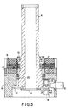
- Figure 3 is a detail of a portion of the central section of Figure 2;
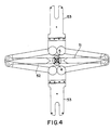
- Figure 4 is a plan view of the device of Figure 1;
- Figure 5 is an isometric sketch of a prior art device;
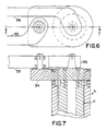
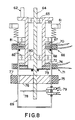
- Figure 6 is a plan view of the device of Figure 1 but modified to drive an articulated arm transfer device of the type disclosed in US 5431529 filed December 28, 1992 by Eastman and Davis and assigned to the assignee of the present application; and
- Figure 7 is a central section along the line 7-7 of Figure 6;
-
- Referring to Figures 1 through 4, a mounting flange 1 is attached to an apertured region of the bottom wall 2 of a vacuum chamber within which an articulated
arm transfer device 3 is supported. The mounting flange itself has a central aperture through which two concentric output shafts extend. The outer shaft is designated 4, and the inner shaft is designated 5. At the extremities of the output shafts within the vacuum chamber a pilot bearing 6 separates the shafts and supports them upon each other. The two shafts are independently rotatable. However, in the preferred embodiment of the invention the relative motion of the shafts is limited to one in which they rotate together, and another in which they rotate in opposite directions. The former motion serves to rotate the articulated arm transfer device, and the latter motion serves to extend and retract the articulated arm transfer device. - The inner shaft is longer than the outer shaft, and the extremity of the inner shaft outside the vacuum chamber extends beyond the corresponding extremity of the outer shaft and attains a maximum outer diameter corresponding to that of the outer shaft. A
rotor 7 is supported on the outer surface of theouter shaft 4, and acorresponding stator 8 is supported outside therotor 7. Similarly, a rotor 9 is supported on the outer surface of theinner shaft 5, and acorresponding stator 10 is supported outside the rotor 9. Each stator is part of a drive which rotates the corresponding shaft. As appears hereinafter, each rotor is inside the vacuum and each stator is outside the vacuum. - Each rotor-
stator pair - Rotary motion is imparted to each shaft by well-known servomechanism techniques, wherein a suitable signal is applied to the coils of the stators.
- The varying position of each shaft as it rotates is detected by a suitable sensing mechanism in combination which a suitable coded disk or the like. For example, a coded pattern of opaque portions on a transparent disk may be caused to pass between a light source and a light detector. In lieu of such an optical sensing mechanism, a magnetic sensing mechanism may be employed wherein a coded pattern of magnetized portions on a magnetic disk may be magnetically scanned. Alternatively, the sensing mechanism may be mechanical, such as a combination of a gear and a switch, or it may be acoustical, with rotation of each shaft producing coded clicks of some sort; even electrostatic systems may be designed. For purposes of illustration, an optical sensing mechanism will now be described.
- A disk 11 is affixed to the outer extremity of the
outer shaft 4 by aclamp plate 12. This disk has a coded pattern of opaque portions which pass between a light-emitting-diode housing 13 and aread head 14, from which a signal is transmitted to the appropriate external circuit through asignal feedthrough 15. The light-emitting-diode housing 13, the readhead 14, and thesignal feedthrough 15 are supported on adrive housing 16 which is fixed and forms part of a vacuum-tighttubular casing 17. Therotor 7 is affixed to theouter shaft 4, and thestator 8 is affixed to thedrive housing 16 by astator clamp 18, positioned so that thestator 8 can co-act with therotor 7; and twobearings outer shaft 4 and thecorresponding drive housing 16 upon which that drive is mounted. Similarly, adisk 31 is affixed to the outer extremity of theinner shaft 5 by aclamp plate 32. This disk has a coded pattern of opaque portions which pass between a light-emitting-diode housing 33 and aread head 34, from which a signal is transmitted to the appropriate external circuit through asignal feedthrough 35. The rotor 9 is affixed to theinner shaft 5, and thestator 10 is affixed to thedrive housing 36 by astator clamp 37, positioned so that thestator 10 can co-act with the rotor 9; and twobearings inner shaft 5 and thecorresponding drive housing 36 upon which that drive is mounted. - The drive housings 16, 36 are of special configuration, and provide an important part of the vacuum-
tight casing 17 which separates the evacuated regions of the device from the atmospheric-air regions of the device. The two drive housings are similar in shape and are connected to each other by anadapter 40. - Vertical motion may be imparted to the shafts by vertical movement of the drive housings which in turn are supported on two
linear slides 41 and two lead screws 42. Alternates to the lead screws with rotary motors may be linear motors (servo or stepper) or a voice-coil or solenoid. The vertically movable drive housings are separated from the mounting flange bysuitable bellows 43, and the outer extremity of the outermost drive housing is closed off by anend cap 44. Thus the entire region within the bellows, drive housings and end cap may be evacuated, and frictional motion inside this evacuated region is limited to that of the various bearings. - Each drive housing has a portion which passes between its respective rotor and stator, and sufficient clearance must be provided between the rotor and this part of the drive housing.
- A prior art device is shown in Figure 5. Rotary motion is imparted to the articulated arm transfer device by rotating the rotate plug. Extension and retraction of the frog-legs is achieved by counter-rotation of the extend/retract drive shafts. The structure of the present invention reduces the number and type of seals required by the use of concentric shafts constructed in a particular way. The prior-art device shows that control may be effected by (1) simple rotation of a shaft and (2) counter-rotation of two shafts. In the device of the invention, (1) is provided when the concentric shafts rotate together and (2) is provided when the concentric shafts counter-rotate. In this device rotary motion is not limited by the basic mechanism, but may continue in either direction for any desired angle.
- The three motions (vertical, rotary and extend/retract) may be simultaneously activated to provide any desired trajectory of the end effector. On the other hand, in some applications all three motions may not necessarily be activated, and the scope of the invention includes devices in which only one or two of the aforementioned three motions are activated.
- Referring now to Figure 4 in conjunction with Figures 1-3, the
outer shaft 4 is connected to oneupper arm 51 and theinner shaft 5 is connected to the otherupper arm 52 of an articulated arm transfer device such as that shown in the aforementioned U.S. patent No. 5,180,276. For motion (i.e. rotation of the end effectors 53) bothrotors 7, 9 turn in synchronism in one direction. For R motion (i.e. extension and retraction of the end effectors 53) eachrotor 7, 9 mirrors the other with equal but opposite rotation. These motions are computer controlled, using inputs from the two encoders. - When
rotors 7, 9 turn in synchronism in one direction,shafts shafts upper arms shafts outer shaft 4 turns clockwise while theinner shaft 5 turns counterclockwise, theupper arm 51 will turn clockwise and theupper arm 52 will turn counterclockwise. The resulting movement of bothend effectors 53 is downward in Figure 4. Conversely, if theouter shaft 4 turns counterclockwise while theinner shaft 5 turns clockwise, theupper arm 51 will turn counterclockwise and theupper arm 52 will turn clockwise. The resulting movement of bothend effectors 53 is upward in Figure 4. - Referring now to Figures 6 and 7, the
outer shaft 4 has affixed thereto ablock 54 in which theupper slave arm 55 of an articulated arm transfer device such as that shown in the aforementioned US 5431529 is rotatably supported. Theupper drive arm 56 of such an articulated arm transfer device is affixed to theinner shaft 5 so as to rotate therewith. In this case the two shafts rotate in synchronism for motion, but theouter shaft 4 is held fixed and only theinner shaft 5 is rotated for radial motion. - If an articulated arm transfer device of the type shown in the aforementioned U.S. Patents Nos. 4,666,366 and 4,909,701 (such as shown in Figure 5) is made with two concentric shafts, an outer shaft to rotate the arms in motion and an inner shaft to generate extend/retract motion, it is possible to rotate the appropriate shaft combinations with one motor (and encoder) by using two brakes, one of which will lock the inner shaft to the outer shaft, and the other the outer shaft to the casing.
- If the outer shaft is locked to the casing, and the shoulder assembly is mounted on the outer (rotate) shaft, no rotation of the shoulder will be possible. Rotation of the inner shaft by a motor attached to it will generate extend-retract motion as is now done by the extend/retract motor of an articulated arm transfer device of the type shown in Figure 5.
- Conversely, if the inner shaft is locked to the outer shaft, no extend/retract motion is possible. If, therefore, the outer shaft/casing brake is released, rotation of the inner shaft by the motor will result in simultaneously rotating the outer shaft, and therefore in motion.
- If both brakes are locked at the end of each motion, and then the appropriate brake is released, one encoder, when its signal is combined in a computer with the brake command, can indicate the motion of either parameter. If greater precision is required, two encoders, as in Figure 1 (11, 31) may be used.
- By proper design and use of magnetic and non-magnetic materials, it is possible to mount all moving parts, including brake shoes and motor rotors, inside of a sealed cylindrical case, while placing the magnet coils of all components in atmosphere outside the casing. This will eliminate the known outgassing problems and electrical feedthroughs which degrade performance of systems having active electromagnets in vacuum.
- While this mechanism will work with any of the extending arm assemblies typical of robots manufactured by the assignee of the instant application, a particular advantage is achieved when using the aforementioned arm shown in Figures 6 and 7 and used in articulated arm transfer devices of the type disclosed in the aforementioned US 5431529 in that only one driving shaft is required at the shoulder, eliminating the need of gearing on top of the rotating shafts.
Claims (19)
- A transport apparatus having a movable arm assembly (51, 52) and a drive mechanism driven by two motors, the drive mechanism comprising:characterized in thata casing (17) attached to a vacuum chamber, the casing comprising a first and a second housing (16, 36);two electro-magnetic stators (8, 10) at different heights relative to the vacuum chamber, the stators being located outside of the chamber;two rotors (7, 9); andtwo drive shafts (4, 5) located partially in the vacuum chamber, the two shafts being two independently rotatable coaxial shafts (4, 5), a first inner shaft (5) extending coaxially through a second outer shaft (4), each shaft (4, 5) having a rotor (7, 9) that is aligned with a separate one of the electro-magnetic stators,the motors are brushless DC motors, andthe stators (8, 10) are stationarily connected to a respective housing (16, 36).
- An apparatus as in claim 1 comprising:a mounting flange (1);said first and second housings (16,36) being movable connected to the mounting flange (1) by a vertical movement mechanism (41, 42)
- An apparatus as in claim 1 or 2, wherein the first (16) and the second (36) housings are connected one on top of the other.
- An apparatus as in claim 3, wherein the two housings (16,36) are connected by an adapter (40).
- An apparatus as in claim 3, wherein a first stator (8) is directly connected to a first housing (16) and a second stator (10) is directly connected to a second housing (36)
- An apparatus as in claim 1 further comprising two bearings (19, 20, 38, 39) between each one of the first and second coaxial shafts and the housings (16,36).
- An apparatus as in claim 2, wherein the vertical movement mechanism (41,42) is connected to a top of a housing for moving both the housings and the drive shaft assembly in vertical direction.
- An apparatus as in claim 7, wherein the housings are connected to a mounting flange (1) of the apparatus by the vertical movement mechanism.
- An apparatus as in claim 8 further comprising bellows (43) that surrounds the drive shaft assembly located between the mounting flange and the housings (16,36).
- An apparatus as in claim 1 further comprising sensing means (11-15, 31-35) for independently sensing the angular position of each of the first and second shafts relative to the casing.
- An apparatus as in claim 10, wherein the means for sensing includes two optical disks (11, 31) connected to the drive shaft assembly, each one of the disks being fixedly connected to a separate one of the coaxial shafts, and two light-emitting diodes (13, 33) and two read-heads (14, 34) stationarily connected to the casing at separate spaced locations in the chamber.
- Apparatus as in one of the preceding claims comprising:a vacuum enclosure (2) having an aperture and an end cap (44) mounted over said aperture;a pilot bearing (6) supporting said outer shaft upon said inner shaft; andmeans for causing each of said stators to impress a suitable electromagnetic field upon its respective rotor so as to impart rotary motion thereto.
- An apparatus as in claim 12 comprising:a support;a first upper arm (51) supported on said support so as to be rotatable about a first axis;a second upper arm (52) supported on said support so as to be rotatable about a second axis;means for causing said second upper arm to be driven by rotation of said first upper arm;a first pair of forearms articulated to said first and second upper arms;a second pair of forearms articulated to said first and second upper arms;each of said upper arms being of lesser length than each forearm;first holding means pivotally coupled to said first pair of forearms and second holding means pivotally coupled to said second pair of forearms, an engagement between said first pair of forearms and adapted to prevent rotation of said first holding means, and an engagement between said second pair of forearms and adapted to prevent rotations of said second holding means; anddriving means capable of driving said first upper arm for rotation through an angle in the range of from greater than 120° up to and including 180° to move said first holding means between a first extended position and a first retracted position whilesimultaneously moving said second holding means between a second retracted position and a second extended position.
- An apparatus as in claim 12 comprising:a support;a first upper arm (51) supported on said support so as to be rotatable about a first axis;a second upper arm (52) supported on said support so as to be rotatable about a second axis;a pair of forearms, comprising a first forearm and a second forearm, said pair of forearms being articulated to said first and second upper arms by means of link means;said link means comprising a link, an upper shaft rotatably supported on said link, a lower shaft rotatably supported on said link, and means for causing rotation of one shaft in one sense to cause rotation of the other shaft in the opposite sense;said first upper arm being fixed to said upper shaft;said second upper arm being rotatably mounted on said lower shaft;said first forearm being fixed to said lower shaft;said second forearm being rotatably mounted on said upper shaft;holding means pivotally coupled to said pair of forearms; anddriving means capable of driving at least one of said upper arms for rotation through an angle in the range of from greater than 120° up to and including 180° to move said holding means between an extended position and a retracted position.
- Apparatus as in claim 1 for imparting rotary motion to a device within the vacuum chamber comprising in combination:a vacuum-tight tubular casing of non-magnetic material, said casing having a longitudinal axis,a first shaft (5) being rotatably mounted inside said casing along said axis, said first shaft having a first disk of magnetic material mounted thereon,a second shaft (4) being rotatably mounted inside said casing about said first shaft, said second shaft being tubular and having a second disk of magnetic material mounted thereon outside said second shaft,a first coil mounted outside said casing and adapted to generate a magnetic field in said first disk,a second coil mounted outside said casing and adapted to generate a magnetic field in said second disk,at least said first coil being adapted to generate a first rotating field pattern for rotating said first shaft, said first disk being magnetized in a pattern for being rotated by said first rotating field pattern.
- Apparatus in accordance with claim 15, wherein said second coil is adapted to generate a second rotating field pattern for rotating said second shaft, and wherein said second disk is magnetized in a pattern for being rotated by said second rotating field pattern.
- Apparatus in accordance with claim 1, wherein said electromagnetic field is derived from one or more encoders mounted on one or both of said shafts.
- An apparatus as in one of the claims 13 to 15, wherein the movable arm assembly comprises a first driving arm connected to the first shaft, a second driving arm connected to the second shaft, and a link structure comprising two separated pairs of driven arms.
- An apparatus as in one of the claims 13 to 15, wherein each pair of driven arms are connected to a separate end effector, and one driven arm from each pair of arms is connected to the first driving arm and the other driven arm of each pair of arms is connected to the second driving arm.
Applications Claiming Priority (3)
| Application Number | Priority Date | Filing Date | Title |
|---|---|---|---|
| US4883393A | 1993-04-16 | 1993-04-16 | |
| US48833 | 1993-04-16 | ||
| PCT/US1994/004040 WO1994023911A1 (en) | 1993-04-16 | 1994-04-13 | Articulated arm transfer device |
Publications (4)
| Publication Number | Publication Date |
|---|---|
| EP0696242A1 EP0696242A1 (en) | 1996-02-14 |
| EP0696242A4 EP0696242A4 (en) | 1996-06-26 |
| EP0696242B1 EP0696242B1 (en) | 1998-12-23 |
| EP0696242B2 true EP0696242B2 (en) | 2004-10-13 |
Family
ID=21956683
Family Applications (1)
| Application Number | Title | Priority Date | Filing Date |
|---|---|---|---|
| EP94914144A Expired - Lifetime EP0696242B2 (en) | 1993-04-16 | 1994-04-13 | Articulated arm transfer device |
Country Status (7)
| Country | Link |
|---|---|
| US (3) | US5720590A (en) |
| EP (1) | EP0696242B2 (en) |
| JP (1) | JP2761438B2 (en) |
| KR (1) | KR100303018B1 (en) |
| CN (1) | CN1046654C (en) |
| DE (1) | DE69415517T3 (en) |
| WO (1) | WO1994023911A1 (en) |
Families Citing this family (143)
| Publication number | Priority date | Publication date | Assignee | Title |
|---|---|---|---|---|
| WO1994023911A1 (en) * | 1993-04-16 | 1994-10-27 | Brooks Automation, Inc. | Articulated arm transfer device |
| JP3740770B2 (en) * | 1995-12-28 | 2006-02-01 | 日本精工株式会社 | Sealed actuator |
| US6102164A (en) * | 1996-02-28 | 2000-08-15 | Applied Materials, Inc. | Multiple independent robot assembly and apparatus for processing and transferring semiconductor wafers |
| US5954840A (en) * | 1996-06-13 | 1999-09-21 | Genmark Automation | Universally tiltable Z axis drive arm |
| US5955858A (en) | 1997-02-14 | 1999-09-21 | Applied Materials, Inc. | Mechanically clamping robot wrist |
| JP3757016B2 (en) | 1997-02-20 | 2006-03-22 | ローツェ株式会社 | Handling robot |
| US6354791B1 (en) * | 1997-04-11 | 2002-03-12 | Applied Materials, Inc. | Water lift mechanism with electrostatic pickup and method for transferring a workpiece |
| US6059507A (en) * | 1997-04-21 | 2000-05-09 | Brooks Automation, Inc. | Substrate processing apparatus with small batch load lock |
| US5879461A (en) * | 1997-04-21 | 1999-03-09 | Brooks Automation, Inc. | Metered gas control in a substrate processing apparatus |
| JPH10329059A (en) * | 1997-05-30 | 1998-12-15 | Daihen Corp | Two-arm transfer robot device |
| US5894760A (en) * | 1997-06-12 | 1999-04-20 | Brooks Automation, Inc. | Substrate transport drive system |
| US6123502A (en) * | 1997-07-08 | 2000-09-26 | Brooks Automation, Inc. | Substrate holder having vacuum holding and gravity holding |
| US5993142A (en) * | 1997-07-10 | 1999-11-30 | Genmark Automation, Inc. | Robot having multiple degrees of freedom in an isolated environment |
| US5882413A (en) * | 1997-07-11 | 1999-03-16 | Brooks Automation, Inc. | Substrate processing apparatus having a substrate transport with a front end extension and an internal substrate buffer |
| US5837059A (en) * | 1997-07-11 | 1998-11-17 | Brooks Automation, Inc. | Automatic positive pressure seal access door |
| JP3806812B2 (en) * | 1997-07-16 | 2006-08-09 | 株式会社ダイヘン | 2-arm type transfer robot |
| JPH1138909A (en) * | 1997-07-18 | 1999-02-12 | Toa Resin Kk | Signboard |
| JP3722598B2 (en) * | 1997-07-16 | 2005-11-30 | 株式会社ダイヘン | 2-arm type transfer robot |
| US6155773A (en) * | 1997-09-22 | 2000-12-05 | Applied Materials, Inc. | Substrate clamping apparatus |
| KR100490053B1 (en) * | 1997-09-25 | 2005-09-02 | 삼성전자주식회사 | Glass Stage for Liquid Crystal Display |
| JPH11188671A (en) * | 1997-12-26 | 1999-07-13 | Daihen Corp | Two-arm transfer robot device |
| JPH11188670A (en) * | 1997-12-26 | 1999-07-13 | Daihen Corp | Two-arm transfer robot device |
| US5931626A (en) * | 1998-01-16 | 1999-08-03 | Brooks Automation Inc. | Robot mounting de-coupling technique |
| US6155768A (en) * | 1998-01-30 | 2000-12-05 | Kensington Laboratories, Inc. | Multiple link robot arm system implemented with offset end effectors to provide extended reach and enhanced throughput |
| JP3519595B2 (en) * | 1998-03-31 | 2004-04-19 | 松下電器産業株式会社 | Wafer transfer device |
| US6547510B1 (en) | 1998-05-04 | 2003-04-15 | Brooks Automation Inc. | Substrate transport apparatus with coaxial drive shafts and dual independent scara arms |
| JPH11333778A (en) | 1998-05-29 | 1999-12-07 | Daihen Corp | Carrying robot device |
| US6224319B1 (en) | 1998-07-10 | 2001-05-01 | Equibe Technologies | Material handling device with overcenter arms and method for use thereof |
| CA2273729A1 (en) * | 1998-07-14 | 2000-01-14 | Bayer Corporation | Robotics for transporting containers and objects within an automated analytical instrument and service tool for servicing robotics |
| JP3863671B2 (en) | 1998-07-25 | 2006-12-27 | 株式会社ダイヘン | Transfer robot |
| US6247889B1 (en) | 1998-07-31 | 2001-06-19 | Bks Lab. Ltd. | Multiple-shaft power transmission apparatus and wafer transport arm link |
| US6464448B1 (en) | 1998-09-01 | 2002-10-15 | Brooks Automation, Inc. | Substrate transport apparatus |
| US6543306B1 (en) | 1998-12-04 | 2003-04-08 | Daihen Corporation | Conveying device |
| JP2000167792A (en) * | 1998-12-04 | 2000-06-20 | Daihen Corp | Transfer device |
| JP2000195939A (en) * | 1998-12-28 | 2000-07-14 | Media Kenkyusho:Kk | Hard disk carrier |
| US6485250B2 (en) * | 1998-12-30 | 2002-11-26 | Brooks Automation Inc. | Substrate transport apparatus with multiple arms on a common axis of rotation |
| US6322312B1 (en) * | 1999-03-18 | 2001-11-27 | Applied Materials, Inc. | Mechanical gripper for wafer handling robots |
| US6318945B1 (en) | 1999-07-28 | 2001-11-20 | Brooks Automation, Inc. | Substrate processing apparatus with vertically stacked load lock and substrate transport robot |
| US6513848B1 (en) | 1999-09-17 | 2003-02-04 | Applied Materials, Inc. | Hydraulically actuated wafer clamp |
| US6265803B1 (en) * | 1999-11-10 | 2001-07-24 | Brooks Automation, Inc. | Unlimited rotation vacuum isolation wire feedthrough |
| US6537011B1 (en) | 2000-03-10 | 2003-03-25 | Applied Materials, Inc. | Method and apparatus for transferring and supporting a substrate |
| JP2001298920A (en) * | 2000-04-18 | 2001-10-26 | Tamagawa Seiki Co Ltd | Two-axis concentric motor |
| US6705816B2 (en) * | 2000-06-09 | 2004-03-16 | Waypoint Technologies | Wafer transport mechanism |
| US6712907B1 (en) | 2000-06-23 | 2004-03-30 | Novellus Systems, Inc. | Magnetically coupled linear servo-drive mechanism |
| DE10032098C2 (en) * | 2000-07-01 | 2003-06-05 | Kuka Roboter Gmbh | robot arm |
| KR100730661B1 (en) | 2000-07-10 | 2007-06-21 | 티에스 코포레이션 | Traction drive speed reducer, Conveyance apparatus using traction drive speed reducer, and Arrangement of two-axis output encoder in conveyance apparatus |
| DE10054045B4 (en) * | 2000-10-31 | 2004-12-30 | Asys Gmbh & Co. Kg | Work table with a table top |
| JP2002212729A (en) * | 2001-01-17 | 2002-07-31 | Hitachi Kokusai Electric Inc | Substrate processing apparatus and semiconductor device manufacturing method |
| KR100428781B1 (en) * | 2001-04-16 | 2004-04-27 | 삼성전자주식회사 | Method and transfer apparatus for wafer |
| GB0130021D0 (en) * | 2001-12-15 | 2002-02-06 | Renishaw Plc | Reaction balanced rotary drive mechanism |
| US6973734B2 (en) * | 2002-02-14 | 2005-12-13 | Faro Technologies, Inc. | Method for providing sensory feedback to the operator of a portable measurement machine |
| US7073271B2 (en) | 2002-02-14 | 2006-07-11 | Faro Technologies Inc. | Portable coordinate measurement machine |
| JP2005517909A (en) * | 2002-02-14 | 2005-06-16 | ファロ テクノロジーズ インコーポレーテッド | Portable coordinate measuring instrument with articulated arm |
| US6957496B2 (en) * | 2002-02-14 | 2005-10-25 | Faro Technologies, Inc. | Method for improving measurement accuracy of a portable coordinate measurement machine |
| US7881896B2 (en) | 2002-02-14 | 2011-02-01 | Faro Technologies, Inc. | Portable coordinate measurement machine with integrated line laser scanner |
| US7519493B2 (en) * | 2002-02-14 | 2009-04-14 | Faro Technologies, Inc. | Portable coordinate measurement machine with integrated line laser scanner |
| US7246030B2 (en) * | 2002-02-14 | 2007-07-17 | Faro Technologies, Inc. | Portable coordinate measurement machine with integrated line laser scanner |
| US6952882B2 (en) * | 2002-02-14 | 2005-10-11 | Faro Technologies, Inc. | Portable coordinate measurement machine |
| USRE42082E1 (en) | 2002-02-14 | 2011-02-01 | Faro Technologies, Inc. | Method and apparatus for improving measurement accuracy of a portable coordinate measurement machine |
| CA2426057C (en) | 2002-04-22 | 2018-03-06 | Milos Misha Subotincic | End effector with multiple pick-up members |
| US7578649B2 (en) | 2002-05-29 | 2009-08-25 | Brooks Automation, Inc. | Dual arm substrate transport apparatus |
| ITTO20020835A1 (en) * | 2002-09-24 | 2004-03-25 | O M V Ohg Venete S Rl | PIECE HOLDER TABLE FOR NUMERICALLY CONTROLLED MACHINE TOOLS |
| JP4000036B2 (en) * | 2002-09-30 | 2007-10-31 | 東京エレクトロン株式会社 | Transport device |
| US7572092B2 (en) | 2002-10-07 | 2009-08-11 | Brooks Automation, Inc. | Substrate alignment system |
| US7077973B2 (en) * | 2003-04-18 | 2006-07-18 | Applied Materials, Inc. | Methods for substrate orientation |
| KR100582697B1 (en) | 2003-07-16 | 2006-05-23 | 동경 엘렉트론 주식회사 | Transportation apparatus and drive mechanism |
| CN100342519C (en) * | 2003-07-16 | 2007-10-10 | 东京毅力科创株式会社 | Conveying device and drive mechanism |
| US7128806B2 (en) * | 2003-10-21 | 2006-10-31 | Applied Materials, Inc. | Mask etch processing apparatus |
| US7458763B2 (en) | 2003-11-10 | 2008-12-02 | Blueshift Technologies, Inc. | Mid-entry load lock for semiconductor handling system |
| US20070269297A1 (en) | 2003-11-10 | 2007-11-22 | Meulen Peter V D | Semiconductor wafer handling and transport |
| US20050223837A1 (en) | 2003-11-10 | 2005-10-13 | Blueshift Technologies, Inc. | Methods and systems for driving robotic components of a semiconductor handling system |
| US10086511B2 (en) | 2003-11-10 | 2018-10-02 | Brooks Automation, Inc. | Semiconductor manufacturing systems |
| US20050133166A1 (en) * | 2003-12-19 | 2005-06-23 | Applied Materials, Inc. | Tuned potential pedestal for mask etch processing apparatus |
| US20050133158A1 (en) * | 2003-12-19 | 2005-06-23 | Applied Materials, Inc. | Mask handler apparatus |
| JP4515133B2 (en) * | 2004-04-02 | 2010-07-28 | 株式会社アルバック | Conveying apparatus, control method therefor, and vacuum processing apparatus |
| US20060207359A1 (en) * | 2004-05-28 | 2006-09-21 | Keith Kowalski | Compact linear/rotary actuator for offset actuation |
| JP4732716B2 (en) * | 2004-06-29 | 2011-07-27 | 株式会社アルバック | Conveying apparatus, control method therefor, and vacuum processing apparatus |
| WO2006006554A1 (en) | 2004-07-09 | 2006-01-19 | Rorze Corporation | Drive source and transportation robot |
| FR2879490B1 (en) * | 2004-12-21 | 2007-03-23 | Tech En Milieu Ionisant Stmi S | MOTORIZED INTERVENTION DEVICE FOR A GLOVE BOX AND A GLOVE BOX EQUIPPED WITH SUCH A DEVICE |
| CN1942288B (en) * | 2005-02-12 | 2010-12-22 | 应用材料公司 | A multi-axis vacuum motor assembly |
| US7604449B1 (en) | 2005-06-27 | 2009-10-20 | Kla-Tencor Technologies Corporation | Equipment front end module |
| CN101310377B (en) * | 2005-11-17 | 2010-11-17 | Oc欧瑞康巴尔斯公司 | Conveyor for disc-shaped workpieces |
| KR101341241B1 (en) | 2006-01-13 | 2013-12-12 | 나부테스코 가부시키가이샤 | Drive apparatus for substrate transfer robot having coolant circulating passage |
| US7946800B2 (en) * | 2007-04-06 | 2011-05-24 | Brooks Automation, Inc. | Substrate transport apparatus with multiple independently movable articulated arms |
| US8752449B2 (en) | 2007-05-08 | 2014-06-17 | Brooks Automation, Inc. | Substrate transport apparatus with multiple movable arms utilizing a mechanical switch mechanism |
| TWI492826B (en) * | 2007-06-27 | 2015-07-21 | Brooks Automation Inc | Robot drive with magnetic spindle bearings |
| US8283813B2 (en) | 2007-06-27 | 2012-10-09 | Brooks Automation, Inc. | Robot drive with magnetic spindle bearings |
| JP5416104B2 (en) | 2007-06-27 | 2014-02-12 | ブルックス オートメーション インコーポレイテッド | Position feedback for self-bearing motors |
| CN101855811B (en) * | 2007-06-27 | 2013-11-20 | 布鲁克斯自动化公司 | Motor stator with lift capability and reduced cogging characteristics |
| US8823294B2 (en) | 2007-06-27 | 2014-09-02 | Brooks Automation, Inc. | Commutation of an electromagnetic propulsion and guidance system |
| KR101659931B1 (en) | 2007-06-27 | 2016-09-26 | 브룩스 오토메이션 인코퍼레이티드 | Multiple dimension position sensor |
| US9752615B2 (en) | 2007-06-27 | 2017-09-05 | Brooks Automation, Inc. | Reduced-complexity self-bearing brushless DC motor |
| WO2009012396A2 (en) * | 2007-07-17 | 2009-01-22 | Brooks Automation, Inc. | Substrate processing apparatus with motors integral to chamber walls |
| ATE549279T1 (en) | 2007-10-10 | 2012-03-15 | Langen Packaging Inc | DEVICE WITH MULTIPLE INTERVENTION DEVICES |
| KR100866094B1 (en) * | 2008-04-28 | 2008-10-30 | 주식회사 싸이맥스 | Independently stacked dual arm robot |
| CN101478194B (en) * | 2009-02-06 | 2012-01-25 | 洛阳轴研科技股份有限公司 | Dual shaft structured high speed precise electric main shaft capable of performing rotation, linear reciprocating movement |
| JP2011205878A (en) * | 2009-12-25 | 2011-10-13 | Canon Anelva Corp | Vacuum actuator and substrate transport robot |
| FR2960637B1 (en) | 2010-05-26 | 2013-04-12 | Moving Magnet Tech | COMPLEX PLAN MOVEMENT EDGE PANEL INDICATING DEVICE |
| JP5563396B2 (en) * | 2010-07-16 | 2014-07-30 | キヤノンアネルバ株式会社 | Actuator and substrate transfer robot |
| JP5620172B2 (en) * | 2010-07-16 | 2014-11-05 | キヤノンアネルバ株式会社 | Substrate transport apparatus, electronic device manufacturing system, and electronic device manufacturing method |
| CN103237634B (en) | 2010-10-08 | 2016-12-14 | 布鲁克斯自动化公司 | coaxial drive vacuum robot |
| US9623555B2 (en) | 2010-11-10 | 2017-04-18 | Brooks Automation, Inc. | Dual arm robot |
| US8918203B2 (en) | 2011-03-11 | 2014-12-23 | Brooks Automation, Inc. | Substrate processing apparatus |
| KR101611586B1 (en) * | 2011-05-16 | 2016-04-11 | 가부시키가이샤 하모닉 드라이브 시스템즈 | Concentric multi-axis actuator |
| US9186799B2 (en) | 2011-07-13 | 2015-11-17 | Brooks Automation, Inc. | Compact direct drive spindle |
| CN110620473B (en) * | 2011-09-16 | 2025-05-06 | 柿子技术公司 | Robotic drive with passive rotor |
| US10476354B2 (en) | 2011-09-16 | 2019-11-12 | Persimmon Technologies Corp. | Robot drive with isolated optical encoder |
| US10569430B2 (en) | 2011-09-16 | 2020-02-25 | Persimmon Technologies Corporation | Low variability robot |
| US9202733B2 (en) | 2011-11-07 | 2015-12-01 | Persimmon Technologies Corporation | Robot system with independent arms |
| FR2982715B1 (en) | 2011-11-14 | 2013-11-15 | Moving Magnet Tech | INDICATOR MODULE FOR A FLUID MOTION DASHBOARD |
| TWI725303B (en) * | 2012-02-10 | 2021-04-21 | 美商布魯克斯自動機械公司 | Substrate processing apparatus |
| KR101327267B1 (en) * | 2012-04-26 | 2013-11-11 | 한양대학교 에리카산학협력단 | Driving force transmission apparatus for end-effector |
| KR101710770B1 (en) * | 2012-05-18 | 2017-02-27 | 비코 인스트루먼츠 인코포레이티드 | Rotary Disk Reactor with Ferrofluid Seal for Chemical Vapor Deposition |
| JP5617900B2 (en) * | 2012-11-19 | 2014-11-05 | 株式会社安川電機 | robot |
| CN103192384B (en) * | 2013-03-11 | 2015-08-19 | 上海交通大学 | A kind of permanent vacuum axle system device of integrated rotary transformer |
| CN104029198A (en) * | 2013-07-27 | 2014-09-10 | 昆山昊旺机械有限公司 | Manipulator |
| CN104511899A (en) * | 2013-09-27 | 2015-04-15 | 中日龙(襄阳)机电技术开发有限公司 | Biaxial numerical control electric posture portion mechanism |
| KR102224756B1 (en) | 2013-11-13 | 2021-03-08 | 브룩스 오토메이션 인코퍼레이티드 | Sealed robot drive |
| WO2015073658A1 (en) | 2013-11-13 | 2015-05-21 | Brooks Automation, Inc. | Sealed switched reluctance motor |
| TWI695447B (en) | 2013-11-13 | 2020-06-01 | 布魯克斯自動機械公司 | Transport apparatus |
| KR102383699B1 (en) | 2013-11-13 | 2022-04-06 | 브룩스 오토메이션 인코퍼레이티드 | Method and apparatus for brushless electrical machine control |
| US11587813B2 (en) | 2013-12-17 | 2023-02-21 | Brooks Automation Us, Llc | Substrate transport apparatus |
| US10134621B2 (en) * | 2013-12-17 | 2018-11-20 | Brooks Automation, Inc. | Substrate transport apparatus |
| TWI657524B (en) * | 2013-12-17 | 2019-04-21 | 美商布魯克斯自動機械公司 | Substrate transport apparatus |
| WO2015112538A1 (en) | 2014-01-21 | 2015-07-30 | Persimmon Technologies, Corp. | Substrate transport vacuum platform |
| WO2015187614A1 (en) * | 2014-06-02 | 2015-12-10 | Eaton Corporation | Devices including an anti-rotation mechanism for a piston and a method of using the same |
| DE102014009892B4 (en) * | 2014-07-04 | 2018-05-30 | gomtec GmbH | Drive unit with magnetic interface |
| CN104785700B (en) * | 2015-03-26 | 2017-05-10 | 上海大学 | Manipulator device of multistage cold former |
| CN105427872B (en) * | 2015-10-30 | 2018-06-08 | 芜湖市振华戎科智能科技有限公司 | A kind of clamping device of secrecy CD finishing equipment integrating |
| JP6415758B2 (en) * | 2016-01-27 | 2018-10-31 | 三菱電機株式会社 | Magnetization method, rotor, electric motor and scroll compressor |
| JP6407456B2 (en) * | 2016-01-27 | 2018-10-17 | 三菱電機株式会社 | Rotor, magnetizing method, electric motor and scroll compressor |
| US10576644B2 (en) | 2017-03-31 | 2020-03-03 | Kinova Inc. | Articulated mechanism with internal brake assembly |
| US10903107B2 (en) | 2017-07-11 | 2021-01-26 | Brooks Automation, Inc. | Semiconductor process transport apparatus comprising an adapter pendant |
| US11088004B2 (en) | 2018-01-30 | 2021-08-10 | Brooks Automation, Inc. | Automatic wafer centering method and apparatus |
| US11574830B2 (en) | 2018-03-16 | 2023-02-07 | Brooks Automation Us, Llc | Substrate transport apparatus |
| JP7723602B2 (en) * | 2019-02-14 | 2025-08-14 | パーシモン テクノロジーズ コーポレイション | Magnetically guided material handling robot. |
| JP7313790B2 (en) * | 2019-08-02 | 2023-07-25 | 株式会社ハーモニック・ドライブ・システムズ | rotary actuator |
| JP7555113B2 (en) * | 2021-02-12 | 2024-09-24 | サーパス工業株式会社 | Tube Pump |
| CN113843775B (en) * | 2021-09-30 | 2025-09-02 | 达闼机器人股份有限公司 | A dual-degree-of-freedom actuator, robotic arm, and robot |
| CN113843772B (en) * | 2021-09-30 | 2025-07-04 | 达闼机器人股份有限公司 | Anti-twisting wire actuator, robotic arm and robot |
| CN114313838A (en) * | 2021-11-24 | 2022-04-12 | 费勉仪器科技(上海)有限公司 | Vacuum driving mechanism and vacuum sample conveying equipment comprising same |
| KR20250142028A (en) * | 2024-03-21 | 2025-09-30 | (주) 코모텍 | Assembly Of Multiple Motor Modules And Device For Transporting Semiconductor Wafers Including The Same |
| WO2026054775A1 (en) * | 2024-09-06 | 2026-03-12 | Saia-Burgess Llc | Dual motor input in friction drive systems |
Citations (1)
| Publication number | Priority date | Publication date | Assignee | Title |
|---|---|---|---|---|
| EP0512516A1 (en) † | 1991-05-08 | 1992-11-11 | Koyo Seiko Co., Ltd. | Magnetic drive device |
Family Cites Families (42)
| Publication number | Priority date | Publication date | Assignee | Title |
|---|---|---|---|---|
| US1190215A (en) * | 1913-06-17 | 1916-07-04 | Joseph Becker | Linkage. |
| US2282608A (en) * | 1940-04-17 | 1942-05-12 | Sun Rubber Co | Hoist |
| US3768714A (en) * | 1969-10-06 | 1973-10-30 | Memorex Corp | Microfilm printer |
| US3730595A (en) * | 1971-11-30 | 1973-05-01 | Ibm | Linear carrier sender and receiver |
| US3823836A (en) * | 1973-05-22 | 1974-07-16 | Plat General Inc | Vacuum apparatus for handling sheets |
| US3874525A (en) * | 1973-06-29 | 1975-04-01 | Ibm | Method and apparatus for handling workpieces |
| JPS5920267B2 (en) * | 1975-10-22 | 1984-05-11 | 株式会社日立製作所 | Electric motor with frequency generator |
| US4062463A (en) * | 1976-05-11 | 1977-12-13 | Machine Technology, Inc. | Automated single cassette load mechanism for scrubber |
| US4208159A (en) * | 1977-07-18 | 1980-06-17 | Tokyo Ohka Kogyo Kabushiki Kaisha | Apparatus for the treatment of a wafer by plasma reaction |
| US4909701A (en) * | 1983-02-14 | 1990-03-20 | Brooks Automation Inc. | Articulated arm transfer device |
| US4666366A (en) * | 1983-02-14 | 1987-05-19 | Canon Kabushiki Kaisha | Articulated arm transfer device |
| JPS606372A (en) * | 1983-06-24 | 1985-01-14 | ぺんてる株式会社 | Motor multiple freedom-degree robot |
| JPS60146689A (en) * | 1984-01-07 | 1985-08-02 | 新明和工業株式会社 | Multi-joint robot |
| JPS61121880A (en) * | 1984-11-19 | 1986-06-09 | 松下電器産業株式会社 | Direct drive robot |
| US4702668A (en) * | 1985-01-24 | 1987-10-27 | Adept Technology, Inc. | Direct drive robotic system |
| US4712971A (en) * | 1985-02-13 | 1987-12-15 | The Charles Stark Draper Laboratory, Inc. | Control arm assembly |
| JPS61244475A (en) * | 1985-04-22 | 1986-10-30 | 株式会社東芝 | Industrial robot |
| US4721971A (en) * | 1986-04-07 | 1988-01-26 | Scott Joel E | Photograph logging apparatus and method |
| JPS6315750A (en) * | 1986-07-07 | 1988-01-22 | Teraoka Seiko Co Ltd | Label printer |
| FR2605158B1 (en) * | 1986-09-25 | 1993-08-20 | Alsthom | SUPERCONDUCTING ROTATING ELECTRIC MACHINE AND ITS THERMAL ISOLATION |
| US4951601A (en) * | 1986-12-19 | 1990-08-28 | Applied Materials, Inc. | Multi-chamber integrated process system |
| JPS63162176A (en) * | 1986-12-24 | 1988-07-05 | フアナツク株式会社 | First arm structure of horizontal joint type robot |
| DE3704505A1 (en) * | 1987-02-13 | 1988-08-25 | Leybold Ag | INSERT UNIT FOR VACUUM SYSTEMS |
| US4784010A (en) * | 1987-04-27 | 1988-11-15 | Graco Robotics Inc. | Electric robotic work unit |
| JPH01120336A (en) * | 1987-11-04 | 1989-05-12 | Daicel Huels Ltd | Composite metal plate |
| CN87205305U (en) * | 1987-11-24 | 1988-07-20 | 王守觉 | Transmission for manipulator |
| JPH01177990A (en) * | 1987-12-28 | 1989-07-14 | Pentel Kk | Direct drive robot |
| FR2633863A1 (en) * | 1988-07-07 | 1990-01-12 | Margery Alain | Handling robot with circular horizontal movement |
| JP2531261B2 (en) * | 1988-07-08 | 1996-09-04 | 富士電機株式会社 | Transfer device |
| US5447409A (en) * | 1989-10-20 | 1995-09-05 | Applied Materials, Inc. | Robot assembly |
| DE69032945T2 (en) * | 1989-10-20 | 1999-09-16 | Applied Materials, Inc. | Robotic device |
| JP2808826B2 (en) * | 1990-05-25 | 1998-10-08 | 松下電器産業株式会社 | Substrate transfer device |
| JP2667284B2 (en) * | 1990-07-26 | 1997-10-27 | シャープ株式会社 | Video tape recorder with answering machine function |
| WO1992005922A1 (en) * | 1990-09-27 | 1992-04-16 | Genmark Automation | Vacuum elevator |
| US5180955A (en) * | 1990-10-11 | 1993-01-19 | International Business Machines Corporation | Positioning apparatus |
| JP3196218B2 (en) * | 1991-01-10 | 2001-08-06 | ソニー株式会社 | Wafer transfer device and wafer transfer method |
| US5209699A (en) * | 1991-02-26 | 1993-05-11 | Koyo Seiko Co., Ltd | Magnetic drive device |
| JP3013264B2 (en) * | 1991-02-26 | 2000-02-28 | 光洋精工株式会社 | Magnetic levitation actuator |
| US5180276A (en) * | 1991-04-18 | 1993-01-19 | Brooks Automation, Inc. | Articulated arm transfer device |
| JP3030667B2 (en) * | 1991-07-29 | 2000-04-10 | 東京エレクトロン株式会社 | Transfer device |
| US5431529A (en) * | 1992-12-28 | 1995-07-11 | Brooks Automation, Inc. | Articulated arm transfer device |
| WO1994023911A1 (en) * | 1993-04-16 | 1994-10-27 | Brooks Automation, Inc. | Articulated arm transfer device |
-
1994
- 1994-04-13 WO PCT/US1994/004040 patent/WO1994023911A1/en not_active Ceased
- 1994-04-13 JP JP6523409A patent/JP2761438B2/en not_active Expired - Lifetime
- 1994-04-13 EP EP94914144A patent/EP0696242B2/en not_active Expired - Lifetime
- 1994-04-13 KR KR1019950704522A patent/KR100303018B1/en not_active Expired - Lifetime
- 1994-04-13 DE DE69415517T patent/DE69415517T3/en not_active Expired - Lifetime
- 1994-04-13 CN CN94191774A patent/CN1046654C/en not_active Expired - Lifetime
-
1995
- 1995-05-03 US US08/434,012 patent/US5720590A/en not_active Expired - Lifetime
-
1996
- 1996-10-30 US US08/740,496 patent/US5813823A/en not_active Expired - Lifetime
-
1997
- 1997-10-24 US US08/957,141 patent/US5899658A/en not_active Expired - Lifetime
Patent Citations (1)
| Publication number | Priority date | Publication date | Assignee | Title |
|---|---|---|---|---|
| EP0512516A1 (en) † | 1991-05-08 | 1992-11-11 | Koyo Seiko Co., Ltd. | Magnetic drive device |
Also Published As
| Publication number | Publication date |
|---|---|
| CN1121331A (en) | 1996-04-24 |
| DE69415517T2 (en) | 1999-05-20 |
| EP0696242A1 (en) | 1996-02-14 |
| US5899658A (en) | 1999-05-04 |
| EP0696242A4 (en) | 1996-06-26 |
| KR100303018B1 (en) | 2001-11-22 |
| EP0696242B1 (en) | 1998-12-23 |
| JP2761438B2 (en) | 1998-06-04 |
| DE69415517D1 (en) | 1999-02-04 |
| US5813823A (en) | 1998-09-29 |
| CN1046654C (en) | 1999-11-24 |
| WO1994023911A1 (en) | 1994-10-27 |
| US5720590A (en) | 1998-02-24 |
| JPH08506771A (en) | 1996-07-23 |
| KR960701729A (en) | 1996-03-28 |
| DE69415517T3 (en) | 2005-03-17 |
Similar Documents
| Publication | Publication Date | Title |
|---|---|---|
| EP0696242B2 (en) | Articulated arm transfer device | |
| US5583408A (en) | Two-axis magnetically coupled robot | |
| US5227708A (en) | Two-axis magnetically coupled robot | |
| JP4866504B2 (en) | Substrate transport apparatus, drive system and operation method thereof | |
| US5789878A (en) | Dual plane robot | |
| JP3341060B2 (en) | End station for parallel ion beam ion implanter | |
| US20060245905A1 (en) | Multi-axis vacuum motor assembly | |
| WO2004008611A1 (en) | Motor, robot, substrate loader and exposure system | |
| US20030026547A1 (en) | Actuator mechanism for precision alignment of optical components | |
| JP2001112223A (en) | Vacuum motor and transfer device | |
| JP4365605B2 (en) | Substrate holding apparatus and substrate holding method, and substrate processing apparatus and substrate processing method using the same | |
| US6279490B1 (en) | Epicyclic stage | |
| JP2506356B2 (en) | Wafer transfer device | |
| CN214269374U (en) | Vacuum sample driving device | |
| WO1999063583A2 (en) | Improved method and apparatus for contacting a wafer | |
| KR101676380B1 (en) | Substrate transport apparatus | |
| CN112758696A (en) | Vacuum sample driving device | |
| JPH0828416B2 (en) | Wafer transfer robot | |
| JPH07114231B2 (en) | Wafer transfer robot | |
| KR20000048686A (en) | Coaxial drive elevator | |
| JPH05228881A (en) | Robot | |
| JPH0297268A (en) | magnetic levitation transfer arm |
Legal Events
| Date | Code | Title | Description |
|---|---|---|---|
| PUAI | Public reference made under article 153(3) epc to a published international application that has entered the european phase |
Free format text: ORIGINAL CODE: 0009012 |
|
| 17P | Request for examination filed |
Effective date: 19951108 |
|
| AK | Designated contracting states |
Kind code of ref document: A1 Designated state(s): CH DE FR GB IT LI NL |
|
| A4 | Supplementary search report drawn up and despatched |
Effective date: 19960513 |
|
| AK | Designated contracting states |
Kind code of ref document: A4 Designated state(s): CH DE FR GB IT LI NL |
|
| 17Q | First examination report despatched |
Effective date: 19970530 |
|
| GRAG | Despatch of communication of intention to grant |
Free format text: ORIGINAL CODE: EPIDOS AGRA |
|
| GRAG | Despatch of communication of intention to grant |
Free format text: ORIGINAL CODE: EPIDOS AGRA |
|
| GRAH | Despatch of communication of intention to grant a patent |
Free format text: ORIGINAL CODE: EPIDOS IGRA |
|
| GRAH | Despatch of communication of intention to grant a patent |
Free format text: ORIGINAL CODE: EPIDOS IGRA |
|
| GRAA | (expected) grant |
Free format text: ORIGINAL CODE: 0009210 |
|
| AK | Designated contracting states |
Kind code of ref document: B1 Designated state(s): CH DE FR GB IT LI NL |
|
| REG | Reference to a national code |
Ref country code: CH Ref legal event code: NV Representative=s name: MICHELI & CIE INGENIEURS-CONSEILS Ref country code: CH Ref legal event code: EP |
|
| REF | Corresponds to: |
Ref document number: 69415517 Country of ref document: DE Date of ref document: 19990204 |
|
| ET | Fr: translation filed | ||
| PLBQ | Unpublished change to opponent data |
Free format text: ORIGINAL CODE: EPIDOS OPPO |
|
| PLBI | Opposition filed |
Free format text: ORIGINAL CODE: 0009260 |
|
| PLBF | Reply of patent proprietor to notice(s) of opposition |
Free format text: ORIGINAL CODE: EPIDOS OBSO |
|
| PLBF | Reply of patent proprietor to notice(s) of opposition |
Free format text: ORIGINAL CODE: EPIDOS OBSO |
|
| 26 | Opposition filed |
Opponent name: INSTITUTE OF TECHNOLOGICAL INFORMATION, INC. Effective date: 19990923 |
|
| NLR1 | Nl: opposition has been filed with the epo |
Opponent name: INSTITUTE OF TECHNOLOGICAL INFORMATION, INC. |
|
| PLBF | Reply of patent proprietor to notice(s) of opposition |
Free format text: ORIGINAL CODE: EPIDOS OBSO |
|
| PLBF | Reply of patent proprietor to notice(s) of opposition |
Free format text: ORIGINAL CODE: EPIDOS OBSO |
|
| PLAW | Interlocutory decision in opposition |
Free format text: ORIGINAL CODE: EPIDOS IDOP |
|
| APAC | Appeal dossier modified |
Free format text: ORIGINAL CODE: EPIDOS NOAPO |
|
| APAE | Appeal reference modified |
Free format text: ORIGINAL CODE: EPIDOS REFNO |
|
| APAE | Appeal reference modified |
Free format text: ORIGINAL CODE: EPIDOS REFNO |
|
| APAC | Appeal dossier modified |
Free format text: ORIGINAL CODE: EPIDOS NOAPO |
|
| REG | Reference to a national code |
Ref country code: GB Ref legal event code: IF02 |
|
| APAC | Appeal dossier modified |
Free format text: ORIGINAL CODE: EPIDOS NOAPO |
|
| APAC | Appeal dossier modified |
Free format text: ORIGINAL CODE: EPIDOS NOAPO |
|
| PLAW | Interlocutory decision in opposition |
Free format text: ORIGINAL CODE: EPIDOS IDOP |
|
| APBU | Appeal procedure closed |
Free format text: ORIGINAL CODE: EPIDOSNNOA9O |
|
| PUAH | Patent maintained in amended form |
Free format text: ORIGINAL CODE: 0009272 |
|
| STAA | Information on the status of an ep patent application or granted ep patent |
Free format text: STATUS: PATENT MAINTAINED AS AMENDED |
|
| 27A | Patent maintained in amended form |
Effective date: 20041013 |
|
| AK | Designated contracting states |
Kind code of ref document: B2 Designated state(s): CH DE FR GB IT LI NL |
|
| REG | Reference to a national code |
Ref country code: CH Ref legal event code: AEN Free format text: AUFRECHTERHALTUNG DES PATENTES IN GEAENDERTER FORM |
|
| NLR2 | Nl: decision of opposition |
Effective date: 20041013 |
|
| NLR3 | Nl: receipt of modified translations in the netherlands language after an opposition procedure | ||
| ET3 | Fr: translation filed ** decision concerning opposition | ||
| APAH | Appeal reference modified |
Free format text: ORIGINAL CODE: EPIDOSCREFNO |
|
| PGFP | Annual fee paid to national office [announced via postgrant information from national office to epo] |
Ref country code: CH Payment date: 20080430 Year of fee payment: 15 |
|
| PGFP | Annual fee paid to national office [announced via postgrant information from national office to epo] |
Ref country code: IT Payment date: 20080429 Year of fee payment: 15 |
|
| PGFP | Annual fee paid to national office [announced via postgrant information from national office to epo] |
Ref country code: FR Payment date: 20080417 Year of fee payment: 15 |
|
| PGFP | Annual fee paid to national office [announced via postgrant information from national office to epo] |
Ref country code: GB Payment date: 20080429 Year of fee payment: 15 |
|
| REG | Reference to a national code |
Ref country code: CH Ref legal event code: PL |
|
| GBPC | Gb: european patent ceased through non-payment of renewal fee |
Effective date: 20090413 |
|
| REG | Reference to a national code |
Ref country code: FR Ref legal event code: ST Effective date: 20091231 |
|
| PG25 | Lapsed in a contracting state [announced via postgrant information from national office to epo] |
Ref country code: LI Free format text: LAPSE BECAUSE OF NON-PAYMENT OF DUE FEES Effective date: 20090430 Ref country code: CH Free format text: LAPSE BECAUSE OF NON-PAYMENT OF DUE FEES Effective date: 20090430 |
|
| PG25 | Lapsed in a contracting state [announced via postgrant information from national office to epo] |
Ref country code: GB Free format text: LAPSE BECAUSE OF NON-PAYMENT OF DUE FEES Effective date: 20090413 Ref country code: FR Free format text: LAPSE BECAUSE OF NON-PAYMENT OF DUE FEES Effective date: 20091222 |
|
| PG25 | Lapsed in a contracting state [announced via postgrant information from national office to epo] |
Ref country code: IT Free format text: LAPSE BECAUSE OF NON-PAYMENT OF DUE FEES Effective date: 20090413 |
|
| PGFP | Annual fee paid to national office [announced via postgrant information from national office to epo] |
Ref country code: DE Payment date: 20130429 Year of fee payment: 20 |
|
| PGFP | Annual fee paid to national office [announced via postgrant information from national office to epo] |
Ref country code: NL Payment date: 20130426 Year of fee payment: 20 |
|
| REG | Reference to a national code |
Ref country code: DE Ref legal event code: R071 Ref document number: 69415517 Country of ref document: DE |
|
| REG | Reference to a national code |
Ref country code: NL Ref legal event code: V4 Effective date: 20140413 |
|
| PG25 | Lapsed in a contracting state [announced via postgrant information from national office to epo] |
Ref country code: DE Free format text: LAPSE BECAUSE OF EXPIRATION OF PROTECTION Effective date: 20140415 |