EP0701023A1 - Dispositif pour le transport et la mise en place des l'éléments en forme de panneaux d'un pavage - Google Patents
Dispositif pour le transport et la mise en place des l'éléments en forme de panneaux d'un pavage Download PDFInfo
- Publication number
- EP0701023A1 EP0701023A1 EP94202507A EP94202507A EP0701023A1 EP 0701023 A1 EP0701023 A1 EP 0701023A1 EP 94202507 A EP94202507 A EP 94202507A EP 94202507 A EP94202507 A EP 94202507A EP 0701023 A1 EP0701023 A1 EP 0701023A1
- Authority
- EP
- European Patent Office
- Prior art keywords
- frame
- clamping element
- feature
- conclusion
- wheels
- Prior art date
- Legal status (The legal status is an assumption and is not a legal conclusion. Google has not performed a legal analysis and makes no representation as to the accuracy of the status listed.)
- Granted
Links
- 239000004575 stone Substances 0.000 description 11
- 239000004576 sand Substances 0.000 description 3
- 240000006829 Ficus sundaica Species 0.000 description 2
- 238000010276 construction Methods 0.000 description 2
- 125000006850 spacer group Chemical group 0.000 description 2
- 230000000284 resting effect Effects 0.000 description 1
- 210000002023 somite Anatomy 0.000 description 1
Images


Classifications
-
- B—PERFORMING OPERATIONS; TRANSPORTING
- B62—LAND VEHICLES FOR TRAVELLING OTHERWISE THAN ON RAILS
- B62B—HAND-PROPELLED VEHICLES, e.g. HAND CARTS OR PERAMBULATORS; SLEDGES
- B62B1/00—Hand carts having only one axis carrying one or more transport wheels; Equipment therefor
- B62B1/02—Hand carts having only one axis carrying one or more transport wheels; Equipment therefor in which the wheel axis is disposed between the load and the handles
- B62B1/06—Hand carts having only one axis carrying one or more transport wheels; Equipment therefor in which the wheel axis is disposed between the load and the handles involving means for grappling or securing in place objects to be carried; Loading or unloading equipment
-
- B—PERFORMING OPERATIONS; TRANSPORTING
- B62—LAND VEHICLES FOR TRAVELLING OTHERWISE THAN ON RAILS
- B62B—HAND-PROPELLED VEHICLES, e.g. HAND CARTS OR PERAMBULATORS; SLEDGES
- B62B1/00—Hand carts having only one axis carrying one or more transport wheels; Equipment therefor
- B62B1/02—Hand carts having only one axis carrying one or more transport wheels; Equipment therefor in which the wheel axis is disposed between the load and the handles
- B62B1/04—Hand carts having only one axis carrying one or more transport wheels; Equipment therefor in which the wheel axis is disposed between the load and the handles involving parts being adjustable, collapsible, attachable, detachable, or convertible
-
- E—FIXED CONSTRUCTIONS
- E01—CONSTRUCTION OF ROADS, RAILWAYS, OR BRIDGES
- E01C—CONSTRUCTION OF, OR SURFACES FOR, ROADS, SPORTS GROUNDS, OR THE LIKE; MACHINES OR AUXILIARY TOOLS FOR CONSTRUCTION OR REPAIR
- E01C19/00—Machines, tools or auxiliary devices for preparing or distributing paving materials, for working the placed materials, or for forming, consolidating, or finishing the paving
- E01C19/52—Apparatus for laying individual preformed surfacing elements, e.g. kerbstones
- E01C19/526—Apparatus for laying individual preformed surfacing elements, e.g. kerbstones hand operated
- E01C19/528—Apparatus for laying individual preformed surfacing elements, e.g. kerbstones hand operated with wheels
Definitions
- the invention relates to a device for the transport and laying of plate-shaped pavement elements, the frame of which is equipped with a clamp on two wheels and can be moved by hand.
- This known device is suitable for transporting heavy paving elements in a vertical position and placing them at their destination.
- the device consists of a frame on two wheels and a vertically and horizontally tiltable clamping device, which consists of movable clamping plates.
- the invention aims at a machine with which it is possible to clamp paving elements from a horizontal position, to lift them up and to deposit them again on a previously smoothed sand bed at the destination.
- Version A of the device is used for heavy concrete paving elements in the formats 40cm x 40cm, 50cm x 50cm, 40cm x 60cm etc.
- Version B of the machine is particularly suitable for laying sidewalks.
- the device is very flexible and enables the road builder to have an almost vertical view of the workplace. This facilitates the correct positioning of the stone slab in relation to the slabs already laid.
- the construction of the device is straightforward, it is cheap to produce, which makes it ideal for the rental industry.
- Model A can easily be converted into a pushcart - it can be used so multifunctional.
- the machine is characterized in that one part of the clamping device is attached to the underside of the frame, while the other part is at a certain distance from it a hinge is attached to the frame.
- This construction makes it possible to increase the distance between the clamping elements by tilting the frame forward or to reduce it by tilting it backwards. If the frame with the fixed clamping element is placed against a stone slab, after which it is tilted forward, the movable clamping element falls over the stone slab. The frame is now tilted backwards, whereby the plate is clamped and lifted up a little. When tilting backwards, the frame must be blocked on the underside, this is easy to do by placing one foot on the wheel axle. The stone slab can now be transported.
- the machine is tilted forward again in such a way that the stone slab lies on the side of the fixed clamping element against the already finished paving.
- the front of the stone slab touches the surface.
- the clamping and frictional force decrease as the distance between the clamping elements increases, the stone slab falls into place at a certain point in time, the slabs connecting very closely to one another.
- the device can now be removed by lifting the movable clamping element with your foot.
- the small axis position is inceimpuls when laying certain patterns, e.g. the so-called mill wing, in which four plates of the format 60 cm x 40 cm form a square of 100 cm x 100 cm.
- the maximum wheelbase that can be used with this pattern is 20 cm.
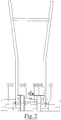
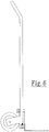
- the movable clamping element 4 (see FIG. 1) is adjustable, so that it can be adapted to the different plate formats. With the help of handle 18 (Fig. 7 + 8), the device becomes a portable device, whereby one can carry the plates. Models without wheels can also be produced if the panels only have to be relocated a short distance apart.
- the invention works as follows: The stone slabs to be laid are supplied in packages in a vertical position.
- the plate that must be picked up by the device must first be placed in a horizontal position. In a simple way, you can tip the plate over with your foot or hand and drop it on a rubber mat, for example.
- the device is positioned so that the fixed clamping element lies against the stone slab. By tilting the frame forward, the fixed clamping element falls over the plate at a certain moment (see Fig. 3).
- the plate is lifted up slightly by tilting the device backwards, one foot pressing on the wheel axle (see Fig. 4).
- the device is now driven with the clamped stone slab over the already paved surface to the destination.
- the clamped plate is now placed against the stone slabs already laid, as shown in FIG. 5.
- the front edge of the plate will first touch the floor, after which the plate as a whole will fall into place. If the slab to be laid has the lower edge of the left or right corner on the pavement that has already been laid, which can easily happen if it is incorrectly positioned, the slab can easily be brought into a good position by tilting the device back and forth. The clamping and frictional forces increase and decrease alternately, causing them to move longitudinally with respect to the fixed clamping element until the plate is perfectly in place.
Landscapes
- Engineering & Computer Science (AREA)
- Chemical & Material Sciences (AREA)
- Combustion & Propulsion (AREA)
- Transportation (AREA)
- Mechanical Engineering (AREA)
- Architecture (AREA)
- Civil Engineering (AREA)
- Structural Engineering (AREA)
- Road Paving Structures (AREA)
- Road Paving Machines (AREA)
Priority Applications (2)
| Application Number | Priority Date | Filing Date | Title |
|---|---|---|---|
| EP19940202507 EP0701023B1 (fr) | 1994-09-02 | 1994-09-02 | Dispositif pour le transport et la mise en place d'éléments en forme de panneaux d'un pavage |
| DE59410027T DE59410027D1 (de) | 1994-09-02 | 1994-09-02 | Vorrichtung für den Transport und das Verlegen plattenförmiger Strassenpflasterung |
Applications Claiming Priority (1)
| Application Number | Priority Date | Filing Date | Title |
|---|---|---|---|
| EP19940202507 EP0701023B1 (fr) | 1994-09-02 | 1994-09-02 | Dispositif pour le transport et la mise en place d'éléments en forme de panneaux d'un pavage |
Publications (2)
| Publication Number | Publication Date |
|---|---|
| EP0701023A1 true EP0701023A1 (fr) | 1996-03-13 |
| EP0701023B1 EP0701023B1 (fr) | 2002-01-09 |
Family
ID=8217157
Family Applications (1)
| Application Number | Title | Priority Date | Filing Date |
|---|---|---|---|
| EP19940202507 Expired - Lifetime EP0701023B1 (fr) | 1994-09-02 | 1994-09-02 | Dispositif pour le transport et la mise en place d'éléments en forme de panneaux d'un pavage |
Country Status (2)
| Country | Link |
|---|---|
| EP (1) | EP0701023B1 (fr) |
| DE (1) | DE59410027D1 (fr) |
Cited By (3)
| Publication number | Priority date | Publication date | Assignee | Title |
|---|---|---|---|---|
| NO20064541A (no) * | 2006-10-06 | 2007-12-27 | Eriksengruppen | Anordning for løfte, transport og legging av belegningsstein. |
| WO2011078669A3 (fr) * | 2009-12-22 | 2011-09-09 | T-Garden | Dispositif permettant de soulever et de transporter des objets |
| NL2022842B1 (en) | 2019-03-29 | 2020-10-06 | Albert Scheringa Frederik | Device for lifting and transporting objects |
Families Citing this family (1)
| Publication number | Priority date | Publication date | Assignee | Title |
|---|---|---|---|---|
| DE102008013973A1 (de) | 2008-03-12 | 2009-09-17 | Wolfgang Ody | Handkarre zum Aufnehmen und Verlegen von Plattenelementen |
Citations (5)
| Publication number | Priority date | Publication date | Assignee | Title |
|---|---|---|---|---|
| US4049284A (en) * | 1976-04-26 | 1977-09-20 | Ronald Capper | Combination hand truck and garden cart |
| GB2172249A (en) * | 1985-03-16 | 1986-09-17 | George Henry Jones | Trolley for facilitating movement and or laying of paving slabs or flags |
| GB2182307A (en) * | 1985-07-04 | 1987-05-13 | Charles John Downey | Paving slab laying trolley |
| DE9102053U1 (de) * | 1990-08-14 | 1991-10-10 | Breu, Michael, 8201 Frasdorf | Handhabungs- und/oder Verlegevorrichtung für Steine |
| NL9300947A (nl) * | 1993-06-02 | 1995-01-02 | Hermanus Willem Johannes Spekm | Inrichting voor het transporteren en leggen van plaatvormige bestratingselementen. |
-
1994
- 1994-09-02 DE DE59410027T patent/DE59410027D1/de not_active Expired - Lifetime
- 1994-09-02 EP EP19940202507 patent/EP0701023B1/fr not_active Expired - Lifetime
Patent Citations (5)
| Publication number | Priority date | Publication date | Assignee | Title |
|---|---|---|---|---|
| US4049284A (en) * | 1976-04-26 | 1977-09-20 | Ronald Capper | Combination hand truck and garden cart |
| GB2172249A (en) * | 1985-03-16 | 1986-09-17 | George Henry Jones | Trolley for facilitating movement and or laying of paving slabs or flags |
| GB2182307A (en) * | 1985-07-04 | 1987-05-13 | Charles John Downey | Paving slab laying trolley |
| DE9102053U1 (de) * | 1990-08-14 | 1991-10-10 | Breu, Michael, 8201 Frasdorf | Handhabungs- und/oder Verlegevorrichtung für Steine |
| NL9300947A (nl) * | 1993-06-02 | 1995-01-02 | Hermanus Willem Johannes Spekm | Inrichting voor het transporteren en leggen van plaatvormige bestratingselementen. |
Cited By (3)
| Publication number | Priority date | Publication date | Assignee | Title |
|---|---|---|---|---|
| NO20064541A (no) * | 2006-10-06 | 2007-12-27 | Eriksengruppen | Anordning for løfte, transport og legging av belegningsstein. |
| WO2011078669A3 (fr) * | 2009-12-22 | 2011-09-09 | T-Garden | Dispositif permettant de soulever et de transporter des objets |
| NL2022842B1 (en) | 2019-03-29 | 2020-10-06 | Albert Scheringa Frederik | Device for lifting and transporting objects |
Also Published As
| Publication number | Publication date |
|---|---|
| DE59410027D1 (de) | 2002-02-14 |
| EP0701023B1 (fr) | 2002-01-09 |
Similar Documents
| Publication | Publication Date | Title |
|---|---|---|
| DE922718C (de) | Strassenbaumaschine | |
| DE2817396A1 (de) | Geraet mit einem fahrbaren wagen mit einem aufrechtstehend angeordneten werkzeug, das zur bodenbearbeitung oder zum stampfen bestimmt ist | |
| EP0701023A1 (fr) | Dispositif pour le transport et la mise en place des l'éléments en forme de panneaux d'un pavage | |
| EP0240801B1 (fr) | Règle pour enduit | |
| DE1534201B1 (de) | Verfahren und Vorrichtung zum maschinellen Verlegen von Formsteinen | |
| DE1261152B (de) | Strassenfertiger, insbesondere fuer Betondecken | |
| DE2408585A1 (de) | Vorzugsweise selbstfahrender hubstapler | |
| DE3802034A1 (de) | Vorrichtung zum bewegen von schachtdeckeln | |
| DE3811186C2 (de) | Gleitschalungsfertiger | |
| DE202019004464U1 (de) | Universelle Verlegevorrichtung für großformatige Beton-, Feinsteinzeugplatten, Fliesen und ähnlichen Platten, Rasenkantensteinen, Betongittersteinen und ähnlichem | |
| CN209759975U (zh) | 一种较大地砖码放铺设装置 | |
| DE8815279U1 (de) | Vorrichtung zum Transportieren von Operationstischen od.dgl. | |
| DE2629066A1 (de) | Vorrichtung zum aufreissen des pflasters einer strassendecke oder dergleichen, welche aus schweren pflastersteinen besteht | |
| DE202009000678U1 (de) | Vorrichtung zum Angreifen, Anheben und Verlegen von Pflastersteinen | |
| DE19536286A1 (de) | Gerät zum Transportieren und Handhaben von palettierten Bodenplatten, Formsteinen und dergleichen Bauelementen | |
| DE7717723U1 (de) | Vorrichtung zum verlegen von bodenplatten | |
| DE102020007692B3 (de) | Plattenheber | |
| DE1122893B (de) | Vorrichtung zum maschinellen Trennen von Asbestzementplatten von ihren Unterlagen und zum getrennten maschinellen Stapeln von Platten und Unterlagen | |
| DE3107761C2 (fr) | ||
| DE10105587C2 (de) | Vorrichtung und Verfahren zum Egalisieren von Pflasterungen | |
| DE8134079U1 (de) | Selbstfahrende vorrichtung zum versetzen transportabler bauelemente | |
| DE20006657U1 (de) | Schubkarre | |
| DE2435369C3 (de) | Vorrichtung zum Heben und Senken eines einen geschlossenen Boden aufweisenden, kastenförmigen Fertigbauteils, insbesondere einer Fertiggarage | |
| NL9300947A (nl) | Inrichting voor het transporteren en leggen van plaatvormige bestratingselementen. | |
| DE19924843C1 (de) | Transporteinrichtung für mindestens ein zeitweilig aufzustellendes Straßenschild |
Legal Events
| Date | Code | Title | Description |
|---|---|---|---|
| PUAI | Public reference made under article 153(3) epc to a published international application that has entered the european phase |
Free format text: ORIGINAL CODE: 0009012 |
|
| AK | Designated contracting states |
Kind code of ref document: A1 Designated state(s): BE DE FR |
|
| RBV | Designated contracting states (corrected) |
Designated state(s): BE DE FR |
|
| 17P | Request for examination filed |
Effective date: 19960821 |
|
| 17Q | First examination report despatched |
Effective date: 19990728 |
|
| GRAG | Despatch of communication of intention to grant |
Free format text: ORIGINAL CODE: EPIDOS AGRA |
|
| GRAG | Despatch of communication of intention to grant |
Free format text: ORIGINAL CODE: EPIDOS AGRA |
|
| GRAH | Despatch of communication of intention to grant a patent |
Free format text: ORIGINAL CODE: EPIDOS IGRA |
|
| GRAH | Despatch of communication of intention to grant a patent |
Free format text: ORIGINAL CODE: EPIDOS IGRA |
|
| GRAA | (expected) grant |
Free format text: ORIGINAL CODE: 0009210 |
|
| AK | Designated contracting states |
Kind code of ref document: B1 Designated state(s): BE DE FR |
|
| REF | Corresponds to: |
Ref document number: 59410027 Country of ref document: DE Date of ref document: 20020214 |
|
| ET | Fr: translation filed | ||
| PLBE | No opposition filed within time limit |
Free format text: ORIGINAL CODE: 0009261 |
|
| STAA | Information on the status of an ep patent application or granted ep patent |
Free format text: STATUS: NO OPPOSITION FILED WITHIN TIME LIMIT |
|
| 26N | No opposition filed | ||
| PGFP | Annual fee paid to national office [announced via postgrant information from national office to epo] |
Ref country code: FR Payment date: 20121015 Year of fee payment: 19 Ref country code: DE Payment date: 20121130 Year of fee payment: 19 Ref country code: BE Payment date: 20121025 Year of fee payment: 19 |
|
| BERE | Be: lapsed |
Owner name: *SPEKMAN HERMANUS WILLEM JOHANNES Effective date: 20130930 |
|
| REG | Reference to a national code |
Ref country code: FR Ref legal event code: ST Effective date: 20140530 |
|
| REG | Reference to a national code |
Ref country code: DE Ref legal event code: R119 Ref document number: 59410027 Country of ref document: DE Effective date: 20140401 |
|
| PG25 | Lapsed in a contracting state [announced via postgrant information from national office to epo] |
Ref country code: BE Free format text: LAPSE BECAUSE OF NON-PAYMENT OF DUE FEES Effective date: 20130930 |
|
| PG25 | Lapsed in a contracting state [announced via postgrant information from national office to epo] |
Ref country code: FR Free format text: LAPSE BECAUSE OF NON-PAYMENT OF DUE FEES Effective date: 20130930 Ref country code: DE Free format text: LAPSE BECAUSE OF NON-PAYMENT OF DUE FEES Effective date: 20140401 |