EP0702162A2 - Adjustable coupling - Google Patents
Adjustable coupling Download PDFInfo
- Publication number
- EP0702162A2 EP0702162A2 EP95300031A EP95300031A EP0702162A2 EP 0702162 A2 EP0702162 A2 EP 0702162A2 EP 95300031 A EP95300031 A EP 95300031A EP 95300031 A EP95300031 A EP 95300031A EP 0702162 A2 EP0702162 A2 EP 0702162A2
- Authority
- EP
- European Patent Office
- Prior art keywords
- axle
- cam
- movable
- toggle
- toggles
- Prior art date
- Legal status (The legal status is an assumption and is not a legal conclusion. Google has not performed a legal analysis and makes no representation as to the accuracy of the status listed.)
- Withdrawn
Links
Images


Classifications
-
- F—MECHANICAL ENGINEERING; LIGHTING; HEATING; WEAPONS; BLASTING
- F16—ENGINEERING ELEMENTS AND UNITS; GENERAL MEASURES FOR PRODUCING AND MAINTAINING EFFECTIVE FUNCTIONING OF MACHINES OR INSTALLATIONS; THERMAL INSULATION IN GENERAL
- F16C—SHAFTS; FLEXIBLE SHAFTS; ELEMENTS OR CRANKSHAFT MECHANISMS; ROTARY BODIES OTHER THAN GEARING ELEMENTS; BEARINGS
- F16C11/00—Pivots; Pivotal connections
- F16C11/04—Pivotal connections
- F16C11/10—Arrangements for locking
Definitions
- the present invention relates to couplings, and relates more particularly to an adjustable coupling for connecting a plurality of frame rods together permitting them to be adjustably retained at desired angular positions.
- Adjustable couplings are intensively used in folding hand trucks and deck chairs to couple frame rods together permitting them to be adjusted relative to one another.
- the disadvantage of these adjustable couplings is that they allow the coupled frame rods to be turned between the operative and collapsed positions or adjusted at limited angles.
- an adjustable coupling comprised of an axle, a fixed toggle mounted around the axle to hold a first frame rod, two movable toggles turned about the axle to hold a second frame rod and a third frame rod respectively, two locating plates mounted around the axle and prohibited from rotary motion relative to the axle and coupled with the movable toggles through a respective toothed joint, two cam plate holders fixed to the axle at two opposite ends, and two cam plates mounted around the axle and engaged with the cam plate holders.
- an adjustable coupling in accordance with the present invention is generally comprised of a first movable toggle 11, a second movable toggle 12, two locating members 13, two coiled springs 14, a first mushroom cam 15, a second mushroom cam 15A, two cam holders 16, and a fixed toggle 19. These elements are respectively mounted around an axle 2 and stopped in place by a headed screw bolt 17 and a screw pin 18.
- the axle 2 is polygonal bar having a first screw hole 23 axially at one end 21 thereof, and a second screw hole 22 spaced from the first screw hole 23 and disposed in a radial direction.
- the fixed toggle 19 comprises a circular shaft 192 having a polygonal bore 191, and an axle housing 193 perpendicularly spaced from the circular shaft 192 for receiving a first frame rod 41.
- the first movable toggle 11 comprises a circular axial hole 112, which receives one end of the circular shaft 192 of the fixed toggle 19, a crown gear 111 around the circular center through hole 112 at an outer end, and an axle housing 113 disposed in a radial direction for receiving a second frame rod 42.
- the second movable toggle 12 comprises a circular axial hole 122, which receives an opposite end of the circular shaft 192, a crown gear 121 (not shown) around the circular center through hole 122 at an outer end, and an axle housing 123 disposed in a radial direction for receiving a third frame rod 43.
- the locating members 13 are respectively coupled to the movable toggles 11 and 12, each having a crown gear 131 meshed with the crown gears 111 and 121 of the movable toggles 11 and 12 and a polygonal center through hole 132 fitting the axle 2.
- the coiled springs 14 are respectively mounted around the axle 2 and stopped between the locating members 13 and the movable toggles 11 and 12.
- the cam plate holders 16 are respectively mounted around the axle 2 at two opposite ends, each having a polygonal center through hole 161, which fits the axle 2, and a projecting portion 162 at an inner side.
- the first and second mushroom cams 15 and 15A are respectively turned around the circular shaft 192 of the fixed toggle 19 and disposed between the locating members 13 and the cam holders 16 and received in the cam holders 16, each having a circular center through hole 153, which receive the circular shaft 192 of the fixed toggle 19, a projecting portion 151 respectively axially stopped against the projecting portions 162 of the cam holders 16, and a handle 152 respectively extended out of the cam holders 16.
- the headed screw bolt 17 and the screw pin 18 are respectively threaded into the first and second screw holes 23 and 22 on the axle 2 to stop all the members in place.
- the mushroom cams 15 and 15A are respectively turned back to let the projecting portions 151 of the mushroom cams 15 and 15A stop against the projecting portions 162 of the cam holders 16 axially, and therefore the locating members 13 are forced to engage with the crown gears 111 and 121 of the movable toggles 11 and 12 again.
Landscapes
- Engineering & Computer Science (AREA)
- General Engineering & Computer Science (AREA)
- Mechanical Engineering (AREA)
- Transmission Devices (AREA)
- Chairs For Special Purposes, Such As Reclining Chairs (AREA)
Abstract
Description
- The present invention relates to couplings, and relates more particularly to an adjustable coupling for connecting a plurality of frame rods together permitting them to be adjustably retained at desired angular positions.
- Adjustable couplings are intensively used in folding hand trucks and deck chairs to couple frame rods together permitting them to be adjusted relative to one another. The disadvantage of these adjustable couplings is that they allow the coupled frame rods to be turned between the operative and collapsed positions or adjusted at limited angles.
- The present invention has been accomplished to provide an adjustable coupling which permits the coupled frame rods to be respectively adjusted through 360° angle. To achieve this object, there is provided an adjustable coupling comprised of an axle, a fixed toggle mounted around the axle to hold a first frame rod, two movable toggles turned about the axle to hold a second frame rod and a third frame rod respectively, two locating plates mounted around the axle and prohibited from rotary motion relative to the axle and coupled with the movable toggles through a respective toothed joint, two cam plate holders fixed to the axle at two opposite ends, and two cam plates mounted around the axle and engaged with the cam plate holders. When the cam plates are disengaged from the cam plate holders, the movable toggles can be disengaged from the locating plates and turned relative to the axle to adjust the angular positions of the second and third frame rods relative to the axle.
-
- Fig. 1 is an exploded view of an adjustable coupling according to the present invention;
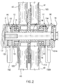
- Fig. 2 is a longitudinal view in section of the adjustable coupling of Figure 1 when installed;
- Fig. 3 is an elevational view of the adjustable coupling shown in Figure 1;
- Fig. 4 is an end view in section of the adjustable coupling shown in Figure 2.
- Referring to the annexed drawings in detail, an adjustable coupling in accordance with the present invention is generally comprised of a first
movable toggle 11, a secondmovable toggle 12, two locatingmembers 13, two coiledsprings 14, afirst mushroom cam 15, asecond mushroom cam 15A, twocam holders 16, and afixed toggle 19. These elements are respectively mounted around anaxle 2 and stopped in place by a headedscrew bolt 17 and ascrew pin 18. - The
axle 2 is polygonal bar having afirst screw hole 23 axially at oneend 21 thereof, and asecond screw hole 22 spaced from thefirst screw hole 23 and disposed in a radial direction. Thefixed toggle 19 comprises acircular shaft 192 having apolygonal bore 191, and anaxle housing 193 perpendicularly spaced from thecircular shaft 192 for receiving afirst frame rod 41. The firstmovable toggle 11 comprises a circularaxial hole 112, which receives one end of thecircular shaft 192 of thefixed toggle 19, acrown gear 111 around the circular center throughhole 112 at an outer end, and anaxle housing 113 disposed in a radial direction for receiving asecond frame rod 42. The secondmovable toggle 12 comprises a circularaxial hole 122, which receives an opposite end of thecircular shaft 192, a crown gear 121 (not shown) around the circular center throughhole 122 at an outer end, and anaxle housing 123 disposed in a radial direction for receiving athird frame rod 43. The locatingmembers 13 are respectively coupled to themovable toggles crown gear 131 meshed with thecrown gears 111 and 121 of themovable toggles hole 132 fitting theaxle 2. The coiledsprings 14 are respectively mounted around theaxle 2 and stopped between the locatingmembers 13 and themovable toggles cam plate holders 16 are respectively mounted around theaxle 2 at two opposite ends, each having a polygonal center throughhole 161, which fits theaxle 2, and a projectingportion 162 at an inner side. The first andsecond mushroom cams circular shaft 192 of thefixed toggle 19 and disposed between the locatingmembers 13 and thecam holders 16 and received in thecam holders 16, each having a circular center throughhole 153, which receive thecircular shaft 192 of thefixed toggle 19, a projectingportion 151 respectively axially stopped against the projectingportions 162 of thecam holders 16, and ahandle 152 respectively extended out of thecam holders 16. When all members are mounted around theaxle 2, the headedscrew bolt 17 and thescrew pin 18 are respectively threaded into the first andsecond screw holes axle 2 to stop all the members in place. - Referring to Figures 2, 3, and 4 again, when the
mushroom cams handles portions 151 of thecam portions 162 of thecam holders 16, thecoiled springs 14 are released from the pressure to push thecrown gears 131 of the locatingmembers 13 away from thecrown gears 111 and 121 of themovable toggles movable toggles fixed toggle 19 to change the angular positions of the second andthird frame rods first frame rod 41. After the adjustment, themushroom cams portions 151 of themushroom cams portions 162 of thecam holders 16 axially, and therefore the locatingmembers 13 are forced to engage with thecrown gears 111 and 121 of themovable toggles
Claims (3)
- An adjustable coupling comprising:
a polygonal axle;
a fixed toggle having a longitudinal shaft mounted around said polygonal axle and prohibited from rotary motion relative to said polygonal axle, and an axle housing perpendicularly connected to the longitudinal shaft of said fixed toggle for holding a frame rod;
a first movable toggle turned about the longitudinal shaft of said fixed toggle at one end, having a crown gear at an outer end and an axle housing disposed in a radial direction relative to the longitudinal shaft of said fixed toggle for receiving a frame rod;
a second movable toggle turned about the longitudinal shaft of said fixed toggle at an opposite end, having a crown gear at an outer end and an axle housing disposed in a radial direction relative to the longitudinal shaft of said fixed toggle for receiving a frame rod;
two locating members respectively mounted around said axle beside said movable toggles and prohibited from rotary motion relative to said axle, each locating member having a crown gear respectively;
two cam holders respectively fastened to said axle at two opposite ends and prohibited from rotary motion relative to said axle, each cam holder having a projecting portion at an inner side;
two mushroom cams respectively turned about said axle and received within said cam holders, each mushroom cam having a projecting portion respectively axially stopped against said projecting portions of said cam holders for forcing said crown gears of said locating members to mesh with said crown gears of said movable toggles;
spring means respectively mounted around said axle and stopped between said locating members and said movable toggles; and
wherein said locating members can be disengaged from said movable toggles by turning said mushroom cam to move said projecting portions of said mushroom cam sideways away from said projecting portions of said cam plate holders, for allowing said movable toggles to be turned about the circular shaft of said fixed toggle to change the angular positions of the axle housings of said movable toggles relative to said axle. - The adjustable coupling of claim 1 wherein said spring means are coiled springs.
- The adjustable coupling of claim 1 wherein said mushroom cams have a respective handle extended out of said cam holders for turning by hand.
Applications Claiming Priority (2)
| Application Number | Priority Date | Filing Date | Title |
|---|---|---|---|
| CN94219370U CN2202821Y (en) | 1994-09-13 | 1994-09-13 | Angle-adjustale elbow joint connector |
| CN94219370 | 1994-09-13 |
Publications (2)
| Publication Number | Publication Date |
|---|---|
| EP0702162A2 true EP0702162A2 (en) | 1996-03-20 |
| EP0702162A3 EP0702162A3 (en) | 1997-05-02 |
Family
ID=5053574
Family Applications (1)
| Application Number | Title | Priority Date | Filing Date |
|---|---|---|---|
| EP95300031A Withdrawn EP0702162A3 (en) | 1994-09-13 | 1995-01-04 | Adjustable coupling |
Country Status (3)
| Country | Link |
|---|---|
| EP (1) | EP0702162A3 (en) |
| CN (1) | CN2202821Y (en) |
| CA (1) | CA2139525C (en) |
Cited By (11)
| Publication number | Priority date | Publication date | Assignee | Title |
|---|---|---|---|---|
| EP0877174A1 (en) * | 1997-05-09 | 1998-11-11 | Yang-Ting Liu | Lockable joint |
| WO2005037035A1 (en) * | 2003-10-16 | 2005-04-28 | Breville Pty Limited | Sandwich press and grill |
| WO2010040644A1 (en) * | 2008-10-10 | 2010-04-15 | Scs (London) Limited | Apparatus and method |
| US20100212513A1 (en) * | 2006-12-20 | 2010-08-26 | Tsann Kuen(China) Enterprise Co., Ltd. | Frying-roasting device |
| WO2012013670A1 (en) | 2010-07-29 | 2012-02-02 | University Of Geneva | Process for the esterification of hyaluronic acid with hydrophobic organic compounds |
| RU2447335C1 (en) * | 2010-11-19 | 2012-04-10 | Открытое Акционерное Общество "Государственное Машиностроительное Конструкторское Бюро "Радуга" Имени А.Я. Березняка" | Fixed hinge |
| EP2662262A3 (en) * | 2012-05-11 | 2016-08-10 | Jonathan Hwan Wang | Folding golf cart |
| FR3070453A1 (en) * | 2017-08-31 | 2019-03-01 | Pierre-Adrien Ducarre | DEVICE FOR QUICK AND UNLINED FOLDING OF WHEELED VEHICLES |
| CN113884439A (en) * | 2021-09-28 | 2022-01-04 | 北京云建标科技有限公司 | Intelligent microorganism identification device and method for activated sludge |
| US11547214B2 (en) * | 2018-12-28 | 2023-01-10 | F. Smit Holding B.V. | Seat, particularly for video games, and hinge for use therein |
| RU2809990C2 (en) * | 2018-12-28 | 2023-12-20 | Ф. Смит Холдинг Б.В. | Video gaming chair and hinge to use it with |
Families Citing this family (3)
| Publication number | Priority date | Publication date | Assignee | Title |
|---|---|---|---|---|
| CN1076089C (en) * | 1997-03-14 | 2001-12-12 | 刘洋廷 | Adjustable two dimension angular shaft toggle |
| CN108224012A (en) * | 2018-03-16 | 2018-06-29 | 安庆师范大学 | A kind of multifunction wall hanging computer equipment |
| CN115076565B (en) * | 2022-07-14 | 2024-07-05 | 衡阳市牛角尖网络科技有限公司 | Tripod with supporting legs capable of being unfolded at multiple angles |
Family Cites Families (3)
| Publication number | Priority date | Publication date | Assignee | Title |
|---|---|---|---|---|
| FR2508989A1 (en) * | 1981-07-03 | 1983-01-07 | Puericulture Ste Nle | Adjustable angular swivel clamp for tubes - has two interlocking serrated shells and locking handle with clamp bolt |
| GB2212555B (en) * | 1987-11-17 | 1991-10-09 | Britax Restmor Ltd | Clamping pivot |
| EP0339890B1 (en) * | 1988-04-25 | 1994-03-16 | Maclaren Limited | A frame |
-
1994
- 1994-09-13 CN CN94219370U patent/CN2202821Y/en not_active Expired - Fee Related
-
1995
- 1995-01-04 CA CA 2139525 patent/CA2139525C/en not_active Expired - Fee Related
- 1995-01-04 EP EP95300031A patent/EP0702162A3/en not_active Withdrawn
Cited By (16)
| Publication number | Priority date | Publication date | Assignee | Title |
|---|---|---|---|---|
| EP0877174A1 (en) * | 1997-05-09 | 1998-11-11 | Yang-Ting Liu | Lockable joint |
| EP2364626A3 (en) * | 2003-10-16 | 2011-12-28 | Breville Pty Ltd. | Improved sandwich press and grill |
| WO2005037035A1 (en) * | 2003-10-16 | 2005-04-28 | Breville Pty Limited | Sandwich press and grill |
| US20100212513A1 (en) * | 2006-12-20 | 2010-08-26 | Tsann Kuen(China) Enterprise Co., Ltd. | Frying-roasting device |
| US8672341B2 (en) | 2008-10-10 | 2014-03-18 | Scs (London) Limited | Hinging mechanism for wheeled device |
| JP2012505101A (en) * | 2008-10-10 | 2012-03-01 | エスシーエス(ロンドン)リミテッド | Apparatus and method |
| WO2010040644A1 (en) * | 2008-10-10 | 2010-04-15 | Scs (London) Limited | Apparatus and method |
| RU2561653C2 (en) * | 2008-10-10 | 2015-08-27 | Эс Си Эс (ЛОНДОН) ЛИМИТЕД | Vehicle frame assembly, method for frame assembly locking in raised position, mounting device for child transportation module and method for its mounting, method for vehicle frame assembly transformation in raised position |
| WO2012013670A1 (en) | 2010-07-29 | 2012-02-02 | University Of Geneva | Process for the esterification of hyaluronic acid with hydrophobic organic compounds |
| RU2447335C1 (en) * | 2010-11-19 | 2012-04-10 | Открытое Акционерное Общество "Государственное Машиностроительное Конструкторское Бюро "Радуга" Имени А.Я. Березняка" | Fixed hinge |
| EP2662262A3 (en) * | 2012-05-11 | 2016-08-10 | Jonathan Hwan Wang | Folding golf cart |
| FR3070453A1 (en) * | 2017-08-31 | 2019-03-01 | Pierre-Adrien Ducarre | DEVICE FOR QUICK AND UNLINED FOLDING OF WHEELED VEHICLES |
| US11547214B2 (en) * | 2018-12-28 | 2023-01-10 | F. Smit Holding B.V. | Seat, particularly for video games, and hinge for use therein |
| RU2809990C2 (en) * | 2018-12-28 | 2023-12-20 | Ф. Смит Холдинг Б.В. | Video gaming chair and hinge to use it with |
| TWI846790B (en) * | 2018-12-28 | 2024-07-01 | 荷蘭商斯米特F 股份有限公司 | Seat, particularly for video games, and hinge for use therein |
| CN113884439A (en) * | 2021-09-28 | 2022-01-04 | 北京云建标科技有限公司 | Intelligent microorganism identification device and method for activated sludge |
Also Published As
| Publication number | Publication date |
|---|---|
| CA2139525C (en) | 2000-06-27 |
| EP0702162A3 (en) | 1997-05-02 |
| CN2202821Y (en) | 1995-07-05 |
| CA2139525A1 (en) | 1996-03-14 |
Similar Documents
| Publication | Publication Date | Title |
|---|---|---|
| US5520474A (en) | Adjustable coupling | |
| EP0702162A2 (en) | Adjustable coupling | |
| US6341544B1 (en) | Adjustable head wrench | |
| US5466102A (en) | System for coupling machine tools | |
| CA2167258C (en) | Rapid, tool-less adjusting system for hotstick tooling | |
| US5495672A (en) | Tube cutter | |
| US5388333A (en) | Saw blade adjusting mechanism | |
| US20210018289A1 (en) | Universal pintle mount for a weapon | |
| US5690451A (en) | Depth stop assembly for a portable electric drill | |
| US4535659A (en) | Torque limiting wrench with an audio alarm | |
| CA1164194A (en) | 4-jaw work holding lathe chuck | |
| US4366733A (en) | Socket including adjustable jaws | |
| JP2003053435A (en) | Roll grooving device | |
| US6616133B1 (en) | Linear actuator having an adjustable piston rod | |
| US6216562B1 (en) | Wrench | |
| US5074174A (en) | Socket wrench | |
| US6565074B1 (en) | Rotary clamp having an adjustable pre-stop | |
| KR960006614B1 (en) | Multipurpose tube working tool | |
| US6272952B1 (en) | Double-reversible screwdriver and wrench combination hand tool | |
| EP0457956B1 (en) | Socket wrench | |
| CA1127432A (en) | Rotary impact tool for applying a torque force | |
| US6301999B1 (en) | Ratchet wrench with force balanced pawl | |
| US4955742A (en) | Erectable structure truss attachment joint | |
| KR950703424A (en) | QUICK-CHANGE TOOL HOLDER WITH ADJUSTMENT MECHANISM | |
| US4892016A (en) | Adjustable socket |
Legal Events
| Date | Code | Title | Description |
|---|---|---|---|
| PUAI | Public reference made under article 153(3) epc to a published international application that has entered the european phase |
Free format text: ORIGINAL CODE: 0009012 |
|
| AK | Designated contracting states |
Kind code of ref document: A2 Designated state(s): AT BE CH DE DK ES FR GB GR IE IT LI LU MC NL PT SE |
|
| PUAL | Search report despatched |
Free format text: ORIGINAL CODE: 0009013 |
|
| AK | Designated contracting states |
Kind code of ref document: A3 Designated state(s): AT BE CH DE DK ES FR GB GR IE IT LI LU MC NL PT SE |
|
| 17P | Request for examination filed |
Effective date: 19980113 |
|
| STAA | Information on the status of an ep patent application or granted ep patent |
Free format text: STATUS: THE APPLICATION IS DEEMED TO BE WITHDRAWN |
|
| 18D | Application deemed to be withdrawn |
Effective date: 19980801 |