EP0703120B1 - Aufprall-Wandelement - Google Patents
Aufprall-Wandelement Download PDFInfo
- Publication number
- EP0703120B1 EP0703120B1 EP95810563A EP95810563A EP0703120B1 EP 0703120 B1 EP0703120 B1 EP 0703120B1 EP 95810563 A EP95810563 A EP 95810563A EP 95810563 A EP95810563 A EP 95810563A EP 0703120 B1 EP0703120 B1 EP 0703120B1
- Authority
- EP
- European Patent Office
- Prior art keywords
- wall element
- element according
- wall
- zone
- impact
- Prior art date
- Legal status (The legal status is an assumption and is not a legal conclusion. Google has not performed a legal analysis and makes no representation as to the accuracy of the status listed.)
- Expired - Lifetime
Links
- 238000005192 partition Methods 0.000 claims description 10
- 230000003116 impacting effect Effects 0.000 claims description 8
- 229910052782 aluminium Inorganic materials 0.000 claims description 5
- XAGFODPZIPBFFR-UHFFFAOYSA-N aluminium Chemical compound [Al] XAGFODPZIPBFFR-UHFFFAOYSA-N 0.000 claims description 5
- 239000000463 material Substances 0.000 claims description 4
- 239000011151 fibre-reinforced plastic Substances 0.000 claims description 2
- 239000004411 aluminium Substances 0.000 claims 2
- 239000000758 substrate Substances 0.000 claims 2
- 229920002430 Fibre-reinforced plastic Polymers 0.000 claims 1
- 239000006261 foam material Substances 0.000 claims 1
- 238000009434 installation Methods 0.000 claims 1
- 238000000926 separation method Methods 0.000 claims 1
- 125000006850 spacer group Chemical group 0.000 description 56
- 239000012528 membrane Substances 0.000 description 11
- 208000027418 Wounds and injury Diseases 0.000 description 9
- 238000013461 design Methods 0.000 description 9
- 208000014674 injury Diseases 0.000 description 9
- 230000006378 damage Effects 0.000 description 8
- 238000000418 atomic force spectrum Methods 0.000 description 7
- 238000012360 testing method Methods 0.000 description 6
- 230000003068 static effect Effects 0.000 description 5
- 230000001133 acceleration Effects 0.000 description 4
- 239000006260 foam Substances 0.000 description 4
- 230000003993 interaction Effects 0.000 description 4
- 238000005259 measurement Methods 0.000 description 4
- 238000012546 transfer Methods 0.000 description 4
- 241000264877 Hippospongia communis Species 0.000 description 3
- 238000010521 absorption reaction Methods 0.000 description 3
- 230000006978 adaptation Effects 0.000 description 3
- 238000010276 construction Methods 0.000 description 3
- 230000035515 penetration Effects 0.000 description 3
- 239000007787 solid Substances 0.000 description 3
- 206010019196 Head injury Diseases 0.000 description 2
- -1 aluminum alloys Chemical class 0.000 description 2
- 238000005452 bending Methods 0.000 description 2
- 239000002131 composite material Substances 0.000 description 2
- 238000013016 damping Methods 0.000 description 2
- 230000007423 decrease Effects 0.000 description 2
- 230000002349 favourable effect Effects 0.000 description 2
- 239000000835 fiber Substances 0.000 description 2
- 230000007246 mechanism Effects 0.000 description 2
- 229910052751 metal Inorganic materials 0.000 description 2
- 239000002184 metal Substances 0.000 description 2
- 230000000474 nursing effect Effects 0.000 description 2
- 239000004033 plastic Substances 0.000 description 2
- 229920003023 plastic Polymers 0.000 description 2
- 230000000717 retained effect Effects 0.000 description 2
- 229910000838 Al alloy Inorganic materials 0.000 description 1
- 235000002505 Centaurea nigra Nutrition 0.000 description 1
- 241001073742 Mylopharodon conocephalus Species 0.000 description 1
- 230000009471 action Effects 0.000 description 1
- 230000004913 activation Effects 0.000 description 1
- 238000004026 adhesive bonding Methods 0.000 description 1
- 239000004760 aramid Substances 0.000 description 1
- 229920006231 aramid fiber Polymers 0.000 description 1
- 229920003235 aromatic polyamide Polymers 0.000 description 1
- 230000033228 biological regulation Effects 0.000 description 1
- 230000005540 biological transmission Effects 0.000 description 1
- 210000000988 bone and bone Anatomy 0.000 description 1
- 230000006835 compression Effects 0.000 description 1
- 238000007906 compression Methods 0.000 description 1
- 230000001419 dependent effect Effects 0.000 description 1
- 238000011161 development Methods 0.000 description 1
- 230000018109 developmental process Effects 0.000 description 1
- 230000000694 effects Effects 0.000 description 1
- 229920001971 elastomer Polymers 0.000 description 1
- 239000000806 elastomer Substances 0.000 description 1
- 238000005265 energy consumption Methods 0.000 description 1
- 239000011521 glass Substances 0.000 description 1
- 238000009863 impact test Methods 0.000 description 1
- 210000003127 knee Anatomy 0.000 description 1
- 210000002414 leg Anatomy 0.000 description 1
- 150000002739 metals Chemical class 0.000 description 1
- 238000000034 method Methods 0.000 description 1
- 239000002984 plastic foam Substances 0.000 description 1
- 230000000750 progressive effect Effects 0.000 description 1
- 230000001681 protective effect Effects 0.000 description 1
- 230000003014 reinforcing effect Effects 0.000 description 1
- 238000011160 research Methods 0.000 description 1
- 208000037974 severe injury Diseases 0.000 description 1
- 230000009528 severe injury Effects 0.000 description 1
- 230000001988 toxicity Effects 0.000 description 1
- 231100000419 toxicity Toxicity 0.000 description 1
- 230000007704 transition Effects 0.000 description 1
Images


Classifications
-
- B—PERFORMING OPERATIONS; TRANSPORTING
- B60—VEHICLES IN GENERAL
- B60R—VEHICLES, VEHICLE FITTINGS, OR VEHICLE PARTS, NOT OTHERWISE PROVIDED FOR
- B60R21/00—Arrangements or fittings on vehicles for protecting or preventing injuries to occupants or pedestrians in case of accidents or other traffic risks
- B60R21/02—Occupant safety arrangements or fittings, e.g. crash pads
- B60R21/04—Padded linings for the vehicle interior ; Energy absorbing structures associated with padded or non-padded linings
-
- B—PERFORMING OPERATIONS; TRANSPORTING
- B64—AIRCRAFT; AVIATION; COSMONAUTICS
- B64D—EQUIPMENT FOR FITTING IN OR TO AIRCRAFT; FLIGHT SUITS; PARACHUTES; ARRANGEMENT OR MOUNTING OF POWER PLANTS OR PROPULSION TRANSMISSIONS IN AIRCRAFT
- B64D25/00—Emergency apparatus or devices, not otherwise provided for
- B64D25/02—Supports or holding means for living bodies
- B64D25/04—Seat modifications
-
- B—PERFORMING OPERATIONS; TRANSPORTING
- B60—VEHICLES IN GENERAL
- B60R—VEHICLES, VEHICLE FITTINGS, OR VEHICLE PARTS, NOT OTHERWISE PROVIDED FOR
- B60R21/00—Arrangements or fittings on vehicles for protecting or preventing injuries to occupants or pedestrians in case of accidents or other traffic risks
- B60R21/02—Occupant safety arrangements or fittings, e.g. crash pads
- B60R21/04—Padded linings for the vehicle interior ; Energy absorbing structures associated with padded or non-padded linings
- B60R2021/0414—Padded linings for the vehicle interior ; Energy absorbing structures associated with padded or non-padded linings using energy absorbing ribs
Definitions
- the invention relates to an impact wall element for gently braking a human body hitting an obstacle, especially head impact in vehicles or aircraft according to the preamble of claim 1
- Accidents involving passenger vehicles e.g. in collisions, rollovers, Emergency braking or aircraft emergency landings occur strongly Changes in the vehicle's movement so that the occupants on interior Impact boundaries of the passenger compartment.
- wall elements for Exposed positions are sought, which are as gentle as possible and injuries prevent intercepting of impacting passengers. This generally applies to the case when a human body is moving at a high relative speed Obstacle occurs. This can also occur in stationary systems where the problem is consists of gently absorbing falls and avoiding fall injuries.
- the object of the present invention is to provide a universally usable, light impact wall element which overcomes the disadvantages of previous designs and which, with the smallest possible wall thickness and construction volume and in the shortest possible way, results in a gentle and injury-preventing braking of an impacting human body, especially for head impact.
- the wall element should also be simple and inexpensive to produce and have a firm surface and favorable fire and toxicity behavior.
- the wall element should be usable both for an impact at high speed, for example in vehicles, and at a lower speed in stationary systems.
- the solution to the problem consists in an impact wall element according to claim 1.
- the deformable structural elements of the wall ie the sandwich cover plate with cover layers and support core as well as the spacer elements, work together in such a way that optimally gentle braking takes place in the shortest possible way.
- the dependent claims relate to particularly advantageous developments of the invention with regard to the structural elements, their arrangement, configuration and dimensioning and the functional design for a very wide range of applications.
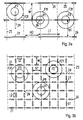
- the structure of the impact wall element 1 according to the invention is shown in the figures la, b shown in two views.
- the wall element has a two-zone structure on, the first zone consisting of a light, plastically deformable sandwich cover plate or cover 10 there is.
- This has a light, deformable Support core 13 with cavities between an upper cover layer 11 and one lower cover layer 12.
- the second zone 20 has plastically deformable Spacer elements 21 which are arranged at intervals from one another and are evenly distributed over the surface of the wall element 1. These spacers 21 carry the cover plate 10 and are on a solid base 5, e.g. in Form a solid wall or on a frame (Fig. 14), supported.
- the fat D2 of the second zone 20 is more than twice the thickness D1 of the first Zone 10.
- the thickness D2 is even three to ten times the thickness D1.
- FIG. 2a shows in cross section Examples of wall-like, flat spacer elements 21.1 to 21.4 and two Examples of arcuate elements 21.6 and 21.7, a tubular one Spacer 21.8. and an element 21.10 with multiple wavy Bends.
- Figure 2b shows an example of a leaf-shaped spacer 21.5 a pre-upsetting bend 22, which is in principle a short version with a Length L2 of the wall-like element 21.1 represents.
- Figure 2c is an example of one columnar spacer 21.9 shown, which for example from cylindrical expanded metal 23 is formed. These can also be one have conical shape 21.11.
- FIG. 3b shows a square arrangement with a smaller lattice constant N1 of e.g. 15 cm shown, so that a very even force distribution of the spacer elements 21 can be reached over the entire wall element surface.
- the spacers are regularly arranged here in longitudinal and transverse rows, with their Length L2 here e.g. is half the size of the lattice constant N1. It is very important that the spacer elements are arranged knot-free 27, i.e. that between the Spacers are always kept a distance and that never longitudinal and transverse spacing elements in a lattice point a node and thus one form strongly increased resistance to deformation here.
- Figure 4 shows arrangement examples with a 60 ° lattice structure 25.
- spacer elements 21 of different sizes are used, in one lattice direction Spacers with a greater length L1 and in the other two directions Elements with a smaller length L2 are regularly arranged.
- the impact surfaces F1, F2, F3 and F11, F21 is illustrated, can also be a compensation of the deformation force contributions of the closest spacer elements become. Regardless of the point of impact, it is essentially the same size Deformation resistance created.
- Figure 4b are in the Lattice points 26 column-like spacing elements 21.9, such as in Figure 2c shown, arranged. This is also a knot-free arrangement, because everyone Spacer elements are evenly spaced from one another here.
- the choice of The arrangement of the spacer elements also depends on the type of solid base 5 on which the impact wall element is supported.
- a frame 45 according to the figure 14 requires very wide distances N1 between the elements 21 while on one fixed wall, a floor or a body also selected narrow distances N1 3b), e.g. N1 can be approximately the same size as the thickness D of the wall element 1. With large distances N1, an additional force compensation can be achieved by reinforcing profiles 24 attached to the cover plate 10, such as 3a and 14 is shown.
- the impact mechanism and the function of the wall structure according to the invention ie the function of the individual structural elements, the sandwich cover plate 10 with cover layers 11, 12 and core 13, the spacer elements 21, and their interaction are explained below with reference to FIGS. 5 to 9.
- the deformation forces of the various elements of the impact wall are adapted to the human body with regard to the deformation properties and the local occurrence of the deformation forces.
- the adaptation to the shape of an impacting body part is created by the cover plate with the two cover layers. This is explained in accordance with FIG. 5 using the example of a head impact with a closely located protruding point such as the nose or chin.
- the forces of the upper cover layer are denoted by A, those of the lower cover layer by B and the forces of the spacer elements by C.
- forces A1 of the upper cover layer 11 occur first, which result in the first shape adaptation to the nose 51.
- forces B of the lower cover layer 12 also occur.
- Figure 6 illustrates those exerted on and by a spacer element 21
- Deformations absorb forces Ktot or energies in the event of an impact not directly on a spacer here (see Fig. 7b).
- membrane forces i.e. Tensile forces KZ and compressive forces KD, on the spacer 21 transmitted.
- this is on a columnar spacer 21.9, which is compressed and bent by the forces C. in the The sandwich top layer with core 13 and one is compared to the starting position Thickness D1 is also compressed or compressed by the pressure forces KD.
- FIG. 7a, b The interaction of the forces A, B, C of the sandwich cover layer 10 and Spacer elements 21 and the resulting deformations are shown in FIG 7a, b further illustrated
- the impact occurs directly on one Spacer 21, which is thus after compression of the cover plate 10 and its Core 13 itself is also compressed by the pressure forces KD.
- the impact occurs between two spacer elements 21.
- FIGS. 7a and 7b correspond to the examples with impact surfaces F3 and F2 of Fig. 3, 4.
- FIGS. 7a and 7b correspond to the examples with impact surfaces F3 and F2 of Fig. 3, 4.
- These two Spacers each compressed half as much as the one central spacer of Fig. 7a.
- the deformation resistance is approximately in both cases of FIGS. 7a and 7b same size.
- the structure, choice of materials and dimensions of the impact wall according to the invention are designed in such a way that they correspond as closely as possible to the functional mechanisms explained.
- the entire structure and especially the cover plate are generally lightweight.
- Tough light metals such as aluminum alloys, such as Ac 110, with a high specific deformation energy absorption are suitable as materials, as well as long fiber or continuous fiber composite materials such as glass and aramid fiber reinforced plastics.
- the sandwich cover plate 10 is relatively soft and not rigid, so that its cover layers 11, 12 can be easily displaced locally against one another.
- the sandwich core 13 itself and its connection to the cover layers, for example by weak gluing, is designed so that only one Surface of several dm 2 noticeable thrust forces are transmitted from the upper cover layer 11 to the lower cover layer 12. This means that the top cover layer can absorb the first local deformations on its own, regardless of the bottom cover layer.
- the sandwich core of the cover plate is also locally compressible by more than 50%. Over distances of 1 dm and more, however, the sandwich core transfers shear forces from the upper cover layer to the lower cover layer and thus their membrane forces also to neighboring spacer elements.
- the cover layers form a loosely coupled double network, which transfers the forces to the spacer elements and at the same time absorbs a local initial deformation relatively softly.
- the spacer elements are constructed and arranged in such a way that they are uniformly deformable, ie compressible and bendable.
- the thicknesses of the cover layers are preferably in a range below 1 mm, for example 0.4-0.7 mm.
- the upper and lower cover layers can also be designed differently in terms of thickness and material, for example 0.4 and 0.6 mm thick, or consist of aluminum and an aramid composite.
- the arrangement of the spacer elements is knot-free and evenly distributed, so that the added bending and compressive forces of the adjacent spacer elements are approximately the same size for all impact points.
- the entire impact wall structure 1 is compressible at any location by over 80%, preferably by at least 90%.
- the light sandwich core 13 preferably has an empty volume fraction of at least 90%. It can consist of foams or, for example, of fine, pre-compressed tube structures.
- the core can also have gaps, can be perforated in a sieve-like manner, can be designed in the form of a lattice or a strip, as is shown as an example in FIGS. Its density is preferably in the range from 40 to 80 kg / m 3 .
- the interaction of forces A, B, C from the top cover layer, from the bottom Cover layer and of the spacer elements is illustrated in the example in FIG. 8, where the forces A, B, C and the resulting impact force Ktot function of the deformation path s is plotted.
- the force A of the upper cover layer increases here 11 in the area of the first zone D1 and then falls off.
- the increase and decrease in the force B of the lower cover layer 12 is much flatter, while the force C of the spacer elements 21 increases relatively continuously.
- the size and shape of the force profiles A and B are due to dimensioning and properties the cover layers 11 and 12 and by the strength of the core 13 and its connection with the cover layers can be influenced and thus adjusted.
- the resulting force Ktot which acts on the impacting body preferably designed as follows, based on FIGS. 10 to 12 is explained.
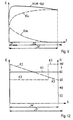
- FIG. 9 illustrates the contribution of the inertial forces Km as a function of the Deformation path s at higher impact speeds.
- the force reached km at the beginning of the impact a peak value corresponding to that then locally strong accelerated portion of the cover plate 10 in the area of the impact. Subsequently the force km drops rapidly.
- HIC V * a1 1.5 /9.81
- FIG. 11 further illustrates the effectiveness of the impact wall 1 according to the invention and its non-elastic impact effect.
- FIG. 11 a shows schematically the non-simultaneous impact of two body parts, ie head 50 and chest 55, on wall element 1.
- FIG. 11b shows the time course of the speed V (t) during the impact.
- head 50 touches the wall at speed V1 and is then braked with a constant deceleration a.
- the chest 55 also hits the wall at the speed V1 when the head has already penetrated the wall.
- the impact wall according to the invention is constructed in such a way that the deformations are practically completely retained at least temporarily, ie for more than the entire duration of the impact, longer than 0.1 s, for example, and are largely retained over a period of minutes.
- FIG. 12 schematically shows examples of possible force profiles K (s) over the deformation path s of impact wall elements.
- W is the maximum deformation path of a wall with a thickness D.
- the force K is proportional to the deceleration a.
- K M * a
- FIG. 12 shows three force profiles K1, K2, K3 (s) over the maximum deformation path W.
- a wall element with a thickness D of only 3 cm and a corresponding deformation range W of at least 2.5 cm achieves the following impact results:
- an impact speed V of approx. 7 m / s can be absorbed and this with a low risk of injury corresponding to a HIC value of 700.
- FIG. 13 illustrates the division of a large wall element into sectors 1a, 1b, 1c.
- large wall surfaces which extend over more than e.g. Can expand 1 m by subdivision into sectors, by means of interruptions at intervals of e.g. 50 up to 80 cm, a uniform deformation characteristic over any size Areas can be reached.
- a partition in front of a row of seats can for example, have a sector 1a, 1b, 1c for each seat.
- This wall division can e.g. by offset slots 36 in one or in both cover plates 11, 12 or by interruption, i.e. Cutting 37 the lower, the upper or both cover layers of the cover plate are formed. This prevents the occurrence too large membrane forces inside large areas.
- By the extent of Subdivision can transfer the membrane force from one sector to the next from 0 to 100%.
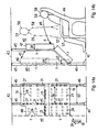
- Figure 14 shows an embodiment in the form of a vehicle or aircraft partition 40.
- the partition 40 with the top of the ceiling 42 and the bottom of the floor 41 of the vehicle fixed, rigid frame made of aluminum profiles 45 is in the direction 43 adjustable. It consists of two wall elements 1, which on the frame 45th are supported.
- the spacer elements 21 are on the frame profiles 45 attached, which are relatively far apart, so that a correspondingly large Distance N1 between the spacer elements 21 exists.
- Stiffening profiles 24 attached to the cover plate.
- These stiffening profiles 24 on the one hand absorb deformation energy on the other hand they also transmit it Impact forces on the spacer elements 21. They exist e.g.
- the upper wall element 1 of the partition faces here a greater thickness D6 of e.g. 13 to 16 cm, while the smaller thickness D7 des lower wall element e.g. 10 to 12 cm.
- D6 a greater thickness of e.g. 13 to 16 cm
- D7 des lower wall element e.g. 10 to 12 cm.
- the top impact wall is primarily for catching the sensitive body parts, especially the head 50, but also the upper body 55 designed, while the lower wall element 1 e.g. on the less sensitive Leg area 57 or, depending on the circumstances, to lower impact speeds and loads is designed.
- the angled position 47 Partition in front of seats 46 with passengers 58, which are secured with a lap belt are appropriate.
- a violent impact e.g.
- the partition 40 is in a front view (FIG. 14a) and in a side view (FIG. 14b).
- FIG. 15 shows a further application of the impact wall elements according to the invention as a shock-absorbing lining for exposed areas in a vehicle interior. Lateral bumps (e.g. in the event of a side collision) or bumps relative to the vehicle roof (e.g. in the event of a rollover) can thus be absorbed.
- This is illustrated here in a partial view with three different wall elements 1: A wall element with a thickness D7 is supported on the vehicle side wall 44, while a wall element with a small thickness D6 (corresponding to lower requirements) is attached to the roof 42. The transition between these two wall elements is formed by a third element 53, which is bent accordingly.
- the wall elements are connected to one another, for example, by connecting elements 35 with a relatively low, meterable power transmission.
- the impact wall elements according to the invention can be used in many areas. These range from the transport area with airplanes and land vehicles to stationary applications in real estate. In the transport sector there is an increasing need for better occupant protection in vehicles in general.
- Foam upholstery and airbag another area of application.
- plastic foam upholstery is very widespread in the interior today.
- the wall elements can generally be used in exposed positions in a vertical, horizontal or inclined position as well as in a flat or curved design to protect belted and unsecured passengers in vehicles, as is the case with high positive or negative accelerations in the direction of travel (impacts on the front or rear of the vehicle ) or on the side, e.g. in the event of a rollover or a side impact of the vehicle.
- the applications include transverse walls (front, rear and subdivisions), side walls, supports on internals, box, headlining.
- the wall elements can be used in passenger vehicles such as airplanes, coaches, trains, rail vehicles, etc. as well as in individual vehicles, especially in mobile homes, station wagons, caravans, campers, where impact protection for non-belted passengers is still very little used.
- Applications in stationary systems in real estate are required where there is a risk that people can hit fixed objects, for example in hospitals, nursing homes, retirement homes.
- the wall elements can be used here as fall-absorbing floors and steps or for side walls in protected rooms of psychiatric institutions.
- the wall element panels on the flat floor 5 have a smaller thickness D4 than the panels laid on steps 6 with a thickness D5.
- the impact in the event of a fall for example on the head 50 and on the knees 57 as a result of a person tripping 54, is indicated with the resulting impact forces K which are not vertical here.
- a fall-absorbing floor in the form of well-known elastomer sheets always results in a certain sinking in under load. This makes walking difficult and gives an unsafe feeling.
- the wall elements according to the invention as floor panels are designed such that they can be walked on without noticeable sinking in, ie the static initial deformation force is designed precisely for this task. In the event of a fall and permanent deformation caused as a result, these plates can easily be replaced.
- the possible fall height of the head on level ground and on stairs results in values for the possible impact speeds of approximately 5 to 8 m / s.
- initial deformation forces of 2000 N and based on 1 dm 2 impact surface result in a surface load of 20 N / cm 2 . This means that the maximum load for walking would be a mass of a maximum of 200 kg on 1 dm 2 contact surface (flat, wide shoe sole) without deformation of the floor element.
- a light carpet overlay 60 on the floor element can provide additional improvements.
- a fall-absorbing floor can be optimally designed from the wall elements according to the invention for a desired application and even for a specific person. Thanks to its low weight and simple construction, this is not only a very powerful, but also a cost-effective solution to the problems.
Landscapes
- Engineering & Computer Science (AREA)
- Mechanical Engineering (AREA)
- Business, Economics & Management (AREA)
- Emergency Management (AREA)
- Aviation & Aerospace Engineering (AREA)
- Vibration Dampers (AREA)
Description
Das Wandelement soll in entsprechender Auslegung sowohl für einen Aufprall mit hoher Geschwindigkeit, z.B in Fahrzeugen, wie auch mit niedrigerer Geschwindigkeit in stationären Anlagen einsetzbar sein.
Die deformierbaren Strukturelemente der Wand, d.h. die Sandwich-Deckplatte mit Deckschichten und Stützkern sowie die Abstandselemente, wirken dabei so zusammen, dass ein optimal schonendes Abbremsen auf kürzestmöglichem Weg erfolgt. Die abhängigen Patentansprüche betreffen besonders vorteilhafte Weiterbildungen der Erfindung bezüglich der Strukturelemente, deren Anordnung, Ausgestaltung und Dimensionierung sowie der funktionalen Auslegung für einen sehr weiten Bereich von Anwendungen.
Es zeigen:
- Fig. 1a, b
- ein erfindungsgemässes Wandelement,
- Fig. 2a, b, c
- verschiedene Beispiele von Abstandselementen,
- Fig. 3, 4
- mögliche gitterartige Anordnungen der Abstandselemente,
- Fig. 5
- die Funktion der Deckplatte,
- Fig. 6
- die Funktion der Abstandselemente,
- Fig. 7
- die kombinierte Funktion der beiden Zonen,
- Fig. 8
- das Zusammenwirken der Kräfte,
- Fig. 9
- den Verlauf der Aufprallkräfte,
- Fig. 10
- einen gemessenen Verlauf der Aufprall-Verzögerung,
- Fig. 11
- den Aufprall zweier Körperteile,
- Fig. 12
- Beispiele von Kraftverläufen,
- Fig. 13
- eine Unterteilung in Wandsektoren,
- Fig. 14
- eine Flugzeugtrennwand,
- Fig. 15
- verschiedene Formen von Wandelementen,
- Fig. 16
- Bodenplatten in stationären Anwendungen.
- Aufprall an einem Gitterpunkt 26 mit den Kreisen F1, F11,
- Aufprall im Zentrum einer Gittermasche mit den Kreisen F2, F21
- und in der Mitte eines Abstandselements 21 mit den Kreisen F3, F31.
Die Kräfte der oberen Deckschicht sind mit A, diejenigen der unteren Deckschicht mit B und die Kräfte der Abstandselemente mit C bezeichnet. Zu Beginn des Aufpralls treten zuerst Kräfte A1 der oberen Deckschicht 11 auf, welche die erste Formanpassung an die Nase 51 ergeben. Anschliessend mit tieferem Eindringen treten zunehmend auch Kräfte B der unteren Deckschicht 12 auf. In der gezeichneten zweiten Deformationslage von Figur 5 sind dies die Kräfte B2 zusätzlich zu den Kräften A2 der oberen Deckschicht sowie die Kräfte C2. Mit weiterem Eindringen werden zunehmend auch Kräfte C der Abstandselemente 21 wirksam. In der gezeichneten dritten Deformationslage sind dies die Kräfte C3 zusätzlich zu den Kräften A3 und B3. Die Richtungen der Membrankräfte der Deckschichten 11 und 12 sind beispielsweise eingezeichnet mit KZ für die Zugkräfte und KD für die Druckkräfte. Die Aufprallfläche F2 des Kopfes 50 wird mit zunehmender Eindringtiefe wirksam, d.h. die Kontaktfläche wird grösser. Mit zunehmendem Deformationsweg und Berührungsfläche des Kopfs 50 mit der Deckplatte treten Stauch- und Biegekräfte der nächsten Abstandselemente sowie zunehmende Membrankräfte der Deckplatte auf. Mit fortschreitendem Deformationsweg werden weiterreichende Membrankräfte und Deformationskräfte weiterer benachbarter Abstandselemente wirksam.
Die Sandwich-Deckplatte 10 ist relativ weich und nicht biegesteif ausgebildet, so dass deren Deckschichten 11, 12 lokal leicht gegeneinander verschiebbar sind. (Die bekannten, sehr biegesteifen Standard-Wabenplatten, deren Waben sehr fest mit den Deckschichten verklebt sind, sind hier absolut ungeeignet.) Der Sandwichkern 13 selber und seine Verbindung mit den Deckschichten, z.B. durch schwache Klebung, ist so ausgelegt, dass erst über eine Fläche von mehreren dm2 spürbare Schubkräfte von der oberen Deckschicht 11 auf die untere Deckschicht 12 übertragen werden. Damit kann die obere Deckschicht die ersten lokalen Deformationen quasi allein aufnehmen, unabhängig von der unteren Deckschicht. Der Sandwichkern der Deckplatte ist zudem lokal um mehr als 50 % stauchbar. Über Entfernungen von 1 dm und mehr überträgt jedoch der Sandwichkern Schubkräfte von der oberen Deckschicht auf die untere Deckschicht und damit deren Membrankräfte auch auf benachbarte Abstandselemente. Vereinfacht gesagt, bilden die Deckschichten ein lose gekoppeltes doppeltes Netz, welches die Kräfte auf die Abstandselemente überträgt und gleichzeitig eine lokale Anfangsdeformation relativ weich aufnimmt.
Die Abstandselemente sind so aufgebaut und angeordnet, dass sie gleichmässig deformierbar, d.h. stauchbar und biegbar sind.
Die Anordnung der Abstandselemente ist knotenfrei und gleichmässig verteilt, so dass die addierten Biege- und Stauchkräfte der benachbarten Abstandselemente für alle Aufprallstellen ungefähr gleich gross sind.
Die ganze Aufprall-Wandstruktur 1 ist an jedem Ort um über 80%, vorzugsweise um mindestens 90 % stauchbar.
Der leichte Sandwichkern 13 weist vorzugsweise einen Leervolumenanteil von mindestens 90% auf. Er kann aus Schaumstoffen oder z.B. auch aus feinen, vorgestauchten Röhrchenstrukturen bestehen. Der Kern kann auch Zwischenräume aufweisen, siebartig gelocht, gitterförmig oder streifenförmig ausgelegt sein, wie dies als Beispiel in den Figuren 7b und 7c an einem Schaumstoffkern mit Löchern 14 gezeigt ist. Vorzugsweise liegt seine Dichte im Bereich von 40 - 80 kg/m3.
Der Kopf wird gleichmässig auf kürzestmöglichem Weg zum Stillstand abgebremst. Der maximale Deformationsweg beträgt W = 159 mm nach Figur 10b. Der resultierende errechnete HIC Wert lag bei nur 746. Der Verzögerungsverlauf a(s) liegt recht gleichmässig im hier angestrebten Bereich von 70 - 80 g und gemäss Kurve a(t) traten nur drei kleine Verzögerungsspitzen mit a > 80 g und einer Dauer von 1 bis 1.5 ms auf.
Nach relativ strengen Kriterien gemäss Luftfahrtvorschriften sind bezüglich des Kopfaufpralls folgende Grenzbedingungen einzuhalten:
- ein HIC Wert (Head Injury Criterion) von max. 1000
- Verzögerungsspitzen mit a > 80 g während höchstens 3 ms.
Für eine konstante Verzögerung a1 errechnet sich der HIC Wert nach:
mit
Dieser berechnete minimale Deformationsweg s1 entspricht gerade dem effektiv gemessenen Deformationsweg W = 159 mm. Zum Vergleich ist dieser berechnete Verlauf a1 ebenfalls in die Figur 10b eingetragen. Wie man sieht, kommt der gemessene Verlauf a (s) dem berechneten Verlauf mit minimal möglichem Deformationsweg s1 und konstanter Verzögerung a1 bei gleichen HIC Werten sehr nahe. Für eine Aufprallgeschwindigkeit von 15 m/s und mit dem Grenzwert von HIC = 1000 ergibt sich nach gleicher Berechnung eine konstante Verzögerung von a1 = 75.3 g und ein minimaler Verzögerungsweg von s1 = 152 mm.
Diese Aufprallbedingungen wären also mit einem erfindungsgemässen Wandelement mit einer Dicke D von nur 16 bis 17 cm erreichbar, was recht nahe ans theoretische, durch die physikalischen Grenzen gegebene Optimum heranreicht.
Zum Zeitpunkt t1 berührt der Kopf 50 mit der Geschwindigkeit V1 die Wand und wird anschliessend mit einer konstanten Verzögerung a gebremst.
Zum Zeitpunkt t2 trifft auch die Brust 55 mit der Geschwindigkeit V1 auf die Wand auf, wenn der Kopf schon in die Wand eingedrungen ist.
Zum Zeitpunkt t3 ist der Kopf 50 zum Stillstand abgebremst (V50 = 0) und hat seinen maximalen Deformationsweg zurückgelegt (Kurve t3 in Fig. 11a). Die Brust ist jedoch erst zur Hälfte abgebremst (V55>0).
Erst im Zeitpunkt t4 ist auch die Brust 55 bis zum Stillstand abgebremst (V55 = 0).
Beide Körperteile 50 und 55 bleiben nun mindestens für kurze Zeit in dieser Deformations-Endlage (Kurve t4 in Fig. 11a). Die Geschwindigkeiten V50 und V55 bleiben also = 0.
Bei rein elastischem Stossverhalten der Wand würde der Kopf gemäss der Geraden VE in Fig. 11b zurückgeschleudert, so dass er zum Zeitpunkt t4, wenn die Brust zum Stillstand gekommen ist, schon eine Rückschlaggeschwindigkeit R50 erreicht hätte. Dies würde das Genick mit entsprechend hohen Kräften zusätzlich sehr ungünstig belasten. Die erfindungsgemässe Aufprallwand ist jedoch so aufgebaut, dass die Deformationen mindestens vorübergehend, d.h. während mehr als der gesamten Aufpralldauer, länger als z.B. 0.1 s, praktisch vollständig erhalten und auch über eine Zeit von Minuten zu einem grossen Teil erhalten bleiben.
K1 verläuft über den ganzen Deformationsbereich mit einer konstanten Verzögerung von 80 g. Dies ergibt bei einer maximal zulässigen Verzögerung von diesen 80 g eine maximal mögliche Energieabsorbtion von E = 80 Einheiten.
Bei K2(s) verläuft die Verzögerung a linear sinkend von anfangs 100 g auf 60 g am Ende des Deformationswegs W. Die Energieabsorption beträgt dann ebenfalls E2 = 80 Einheiten.
Bei K3(s) werden die ersten 80% des Wegs mit einer Verzögerung von a = 60 g und die restlichen 20% mit 100 g zurückgelegt. Dies ergibt eine Energieaufnahme von E3 = 68 Einheiten.
Der Verlauf K2(s) kann für hohe Kopfaufprallgeschwindigkeiten besonders vorteilhaft sein, da er einen tieferen HIC Wert ergibt als bei konstanter Verzögerung über den gleichen Deformationsweg W gemäss K1. Dies, weil anfangs bei höherer Geschwindigkeit eine lokale Verzögerungsspitze (in der Wandstruktur) rascher durchlaufen wird als später tiefer in der Wand und mit entsprechend niedrigerer Geschwindigkeit (gemäss dt = ds / V).
Die Auslegung der Wand gemäss K3 hat eine etwas niedrigere Energieabsoption als bei K1 und K2, dies könnte z.B. folgenden Vorgaben entsprechen:
Aufprallstösse sind relativ sanft abzufangen bis zu einer Aufprallenergie von 48 Einheiten (= 80% * 60 g). Zusätzlich ist aber noch eine Reserve von zusätzlich 20 Energieeinheiten für sehr unwahrscheinliche Fälle eines Aufpralls mit entsprechend höherer Energie vorzusehen. Die letzten 20% des Deformationswegs W mit der Beschleunigung a = 100 g wirken so als Notreserve. Dies kann baulich realisiert werden mit einem Aufprall-Wandelement, bei dem die 1. und 2. Zone (10 und 20) diesen 80% des Deformationswegs entsprechen und wo zusätzlich eine dritte, härtere Zone eingefügt ist zwischen die zweite Zone und die feste Unterlage 5 mit den restlichen 20% des Deformationswegs (vergleiche Figur 1).
Die hohe Wirksamkeit der erfindungsgemässen Wandstruktur wird an einem weiteren Beispiel eines sehr dünnen Aufprall-Wandelements erläutert. Ein Wandelement mit einer Dicke D von nur 3 cm und einem entsprechenden Deformationsbereich W von mindestens 2.5 cm erzielt folgende Aufprallresultate: Mit einer Auslegung auf eine konstante Verzögerung von a = 100 g kann schon eine Aufprallgeschwindigkeit V von ca. 7 m/s abgefangen werden und dies mit einem geringen Verletzungsrisiko entsprechend einem HIC Wert von 700. Dieses sehr gute Resultat ist zu vergleichen mit einem ungedämpften harten Kopfaufprall, welcher schon ab V = 5 m/s schwerste Verletzungen ergeben kann.
Dies sind vor allem die maximale Aufprallgeschwindigkeit V1, der zur Verfügung stehende Platz für die Schichtdicke D sowie die Art der aufzufangenden Körper, d.h. Körperteile, deren Masse sowie Form und Grösse der Aufprallflächen und die zulässigen Kräfte und Verzögerungen. Aus verschiedenen Anwendungsbereichen wie in der Luftfahrt und aus Crashversuchen der Automobilindustrie sind dazu Normen und Grenzwerte ausgearbeitet worden. Diese geben Messnormen und Grenzwerte der zulässigen Kräfte und Beschleunigungen für verschiedene Körperteile und verschiedene Stufen von Verletzungsrisiken an.
Beispielsweise wie folgt:
Zone 10 mit D1 = 15 mm, W1 = 10 mm
Zone 20 mit D2 = 85 mm, W2 = 80 mm, dies gibt bei einer Gesamtdicke mit D = 100 mm einen sehr grossen Deformationsweg W von 90 mm.
Auf die Fahrzeugseitenwand 44 ist ein Wandelement mit einer Dicke D7 abgestützt, während am Dach 42 ein Wandelement mit geringer Dicke D6 (entsprechend tieferen Anforderungen) angebracht ist. Den Übergang zwischen diesen beiden Wandelementen bildet ein drittes Element 53, welches entsprechend gebogen ist. Dies stellt ein Beispiel einer schalenförmigen oder gewölbten Ausführung des erfindungsgemässen Wandelements 1 dar. Je nach Anforderungen können die
Schichtdicken beispielsweise wie folgt ausgelegt sein: D6 = 4- 8 cm, D7 = 6 - 10 cm.
Die Wandelemente sind z.B. durch Verbindungselemente 35 mit relativ geringer, dosierbarer Kraftübertragung untereinander verbunden.
Im Transportbereich besteht ein zunehmender Bedarf an besserem Insassenschutz in Fahrzeugen generell. Hier besteht neben den beiden heute üblichen Systemen
Schaumstoffpolsterungen und Airbag ein weiter Anwendungsbereich.
Auf der kostengünstigen Seite für geringe Anforderungen sind Kunststoffschaum-Polsterungen im Innenraum heute sehr weit verbreitet.
Die Anwendungen umfassen bei Luftfahrzeugen und Landfahrzeugen im Innenraum Querwände (Front-, Heckseite und Unterteilungen), Seitenwände, Auflagen auf Einbauten, Kasten, Dachhimmel. Dabei können die Wandelemente in Passagierfahrzeugen wie Flugzeugen, Reisebussen, Bahnen, Schienenfahrzeugen etc. wie auch in Individualfahrzeugen, im speziellen z.B. in Wohnmobilen, Combiwagen, Caravan, Camper, wo ein Aufprallschutz für nicht angegurtete Passagiere noch sehr wenig angewendet wird, eingesetzt werden.
Anwendungen in stationären Anlagen in Immobilien werden benötigt, wo die Gefahr besteht, dass Personen auf feste Objekte aufschlagen können, z.B. in Spitälern, Pflegeheimen, Alterswohnungen. Die Wandelemente sind hier einsetzbar als falldämpfende Böden und Treppenstufen oder bei Seitenwänden in geschützten Zimmern von psychiatrischen Anstalten.
- definierte hohe Anfangskraft der Verformung,
- gleichmässige und definiert hohe Deformationskraft (bzw. Verzögerung) im Deformationsbereich,
- ein maximal grosser Verformungsweg W bezogen auf die Dicke D des Wandelements,
- weitgehend plastische Verformung, d.h. kurzfristig bleibende Verformung während eines Aufpralls und kein Zurückschlagen des Körpers,
- gute Anpassung der Aufprallfläche an die Form des Körpers.
Dementsprechend haben ältere Personen auch Angst vor Stürzen und den entsprechenden Verletzungsfolgen. Überdies ist ein erhöhter personeller Betreuungsaufwand für deren Pflege erforderlich oder eine verfrühte Übersiedlung in Pflegeheime. Der falldämpfende Bodenbelag nach Figur 16 ergibt nun eine gute Lösung dieser Probleme. Er besteht aus einzelnen Wandelement-Platten 1, welche mit Verbindungselementen 35 so verbunden sind, dass nur eine geringe Übertragung von Membrankräften einer Platte auf die nächste stattfindet. Die Wandelement-Platten auf dem flachen Boden 5 weisen eine geringere Dicke D4 auf als die auf Treppenstufen 6 verlegten Platten mit einer Dicke D5. Der Aufprall bei einem Sturz, z.B. auf den Kopf 50 und auf die Knie 57 infolge Stolperns einer Person 54, ist mit den resultierenden, hier nicht vertikalen Aufschlagkräften K angezeigt. Ein falldämpfender Boden in Form von bekannten Elastomer-Platten ergibt bei Belastung immer ein gewisses Einsinken. Dies erschwert das Begehen und ergibt ein unsicheres Gefühl. Die erfindungsgemässen Wandelemente als Bodenplatten sind dagegen so ausgelegt, dass sie begehbar sind ohne spürbares Einsinken, d.h. die statische Anfangsdeformationskraft ist genau auf diese Aufgabe ausgelegt.
Im Falle eines Sturzes und dadurch verursachter bleibender Deformation können diese Platten jedoch leicht ausgewechselt werden.
Aus der möglichen Fallhöhe des Kopfs auf ebenen Boden und auf Treppen ergeben sich Werte für die möglichen Aufprallgeschwindigkeiten von etwa 5 bis 8 m/s. Daraus wird der resultierende erforderliche Deformationsweg W abgeleitet. Bei konstanter Verzögerung a von 30 bis 50 g beträgt W = V2 / 2a. Daraus ergeben sich Deformationswege von W = 4 bis 10 cm.
Bezogen auf eine Kopfmasse von 5 kg ergeben sich bei einer Verzögerung von a = 40 g Anfangsdeformationskräfte von 2000 N und bezogen auf 1 dm2 Aufprallfläche ergibt dies eine Flächenbelastung von 20 N/cm2. D.h. als maximale Belastung für das Begehen wäre dann auf 1 dm2 Auflagefläche (flache, breite Schuhsohle) eine Masse von entsprechend maximal 200 kg ohne Deformation des Bodenelements zulässig. Eine leichte Teppichauflage 60 auf das Bodenelement kann zusätzliche Verbesserungen ergeben.
Wie erläutert, lässt sich ein falldämpfender Boden aus den erfindungsgemässen Wandelementen optimal auf eine gewünschte Anwendung und sogar auf eine bestimmte Person auslegen. Dank geringem Gewicht und einfacher Bauweise stellt dies nicht nur eine sehr leistungsfähige, sondern auch noch eine kostengünstige Lösung der Probleme dar.
Claims (23)
- Aufprall-Wandelement (1) zum schonenden Abbremsen eines auf ein Hindernis aufprallenden menschlichen Körpers, insbesondere des Kopfaufpralls in Fahrzeugen oder Flugzeugen, welches mindestens zwei Zonen (10, 20) aufweist und wobei die Dicke (D2) der zweiten Zone (20) mindestens das Doppelte der Dicke (D1) der ersten Zone (10) beträgt, wobei die erste Zone aus einer leichten, plastisch deformierbaren Deckplatte (10) mit einer dünnen oberen Deckschicht (11), einer dünnen unteren Deckschicht (12) und einem dazwischen angeordneten leichten, Hohlräume aufweisenden, deformierbaren Stützkern (13) besteht und wobei die zweite Zone (20) plastisch deformierbare Elemente (21) aufweist, welche mit der unteren Deckschicht (12) verbunden und auf eine feste Unterlage (5) abgestützt sind, dadurch gekennzeichnet, dassdie Deckplatte der ersten Zone (10) eine Sandwich-Deckplatte (10) ist und dassdie Elemente der zweiten Zone (20) einzelne, diskrete, voneinander beabstandete Abstandselemente (21) sind, welche die Deckplatte tragen.
- Wandelement nach Anspruch 1, dadurch gekennzeichnet, dass die Dicke D2 der zweiten Zone das 3- bis 10fache der Dicke D1 der ersten Zone beträgt.
- Wandelement nach Anspruch 1, dadurch gekennzeichnet, dass das Gewicht der Deckplatte zwischen 2 und 3.5 kg/m2 liegt.
- Wandelement nach Anspruch 1, dadurch gekennzeichnet, dass die Dicke D1 der Deckplatte (10) zwischen 8 und 20 mm liegt.
- Wandelement nach Anspruch 1, dadurch gekennzeichnet, dass die Deckschichten (11, 12) aus Aluminium bestehen.
- Wandelement nach Anspruch 1, dadurch gekennzeichnet, dass die Deckschichten (11, 12) eine Dicke von 0.4 bis 0.6 mm aufweisen.
- Wandelement nach Anspruch 1, dadurch gekennzeichnet, dass der Stützkern (13) aus einem Schaumstoff aufgebaut ist.
- Wandelement nach Anspruch 1, dadurch gekennzeichnet, dass der Stützkern (13) eine spezifische Dichte von 40 bis 80 kg/m3 aufweist
- Wandelement nach Anspruch 1, dadurch gekennzeichnet, dass die zweite Zone (20) zusätzliche kräfteverteilende Versteifungsprofile (24) aufweist, welche an der Deckplatte (10) angebracht sind.
- Wandelement nach Anspruch 9, dadurch gekennzeichnet, dass die Anordnung der Abstandselemente (21) und allfälliger Versteifungsprofile (24) in der zweiten Zone eine knotenfreie netzartige Struktur (25) bildet.
- Wandelement nach Anspruch 1, dadurch gekennzeichnet, dass die Abstandselemente eine Vorstauchbiegung (22) aufweisen.
- Wandelement nach Anspruch 1, dadurch gekennzeichnet, dass die Abstandselemente (21) aus im wesentlichen senkrecht zur Deckplatte stehenden Wandprofilen (21.1) bestehen.
- Wandelement nach Anspruch 1, dadurch gekennzeichnet, dass die Abstandselemente (21) blattartig (21.5), bogenförmig (21.6), röhrenförmig (21.8) oder säulenförmig (21.9), zylindrisch oder konisch (21.11) ausgebildet sind.
- Wandelement nach Anspruch 1, dadurch gekennzeichnet, dass die Abstandselemente aus 1 - 2mm starkem Aluminiumblech bestehen.
- Wandelement nach Anspruch 1, dadurch gekennzeichnet, dass die Deckschichten (11, 12) und/oder die Abstandselemente (21) aus faserverstärktem Kunststoff bestehen.
- Wandelement nach Anspruch 1, dadurch gekennzeichnet, dass die Dicke D2 der zweiten Zone 5 - 18 cm beträgt.
- Wandelement nach Anspruch 1, dadurch gekennzeichnet, dass die zweite Zone ein Gewicht von 1 bis 3 kg/m2 aufweist.
- Wandelement nach Anspruch 1, dadurch gekennzeichnet, dass der nutzbare Deformationsweg W mindestens 90% der Dicke D des Wandelements beträgt.
- Wandelement nach Anspruch 1, dadurch gekennzeichnet, dass der dynamische Deformationswiderstand des Wandelements für eine kugelförmige Druckfläche mit einem Durchmesser von 15 cm zwischen 2 und 4 kN liegt.
- Wandelement nach Anspruch 1, dadurch gekennzeichnet, dass der dynamische Deformationswiderstand über den nutzbaren Deformationsbereich W einen im wesentlichen konstanten Wert aufweist, mit tendenziell höheren Werten am Anfang.
- Wandelement nach Anspruch 1, dadurch gekennzeichnet, dass das Wandelement in mindestens zwei Sektoren (1a, 1b, 1c) unterteilt ist, wobei die Unterteilung durch mindestens teilweise Durchtrennung (36, 37) der Deckplatte (10) gebildet ist.
- Trennwand (40) vor Passagiersitzen in Fahrzeugen oder Flugzeugen, gekennzeichnet durch mindestens ein Wandelement (1) nach einem der vorangehenden Ansprüche und durch einen beidseitig fixierten Rahmen (45) als feste Unterlage (5).
- Bodenbelag in stationären Anlagen, gekennzeichnet durch mehrere auf einem Boden ausgelegte Wandelemente (1) nach einem der Ansprüche 1 bis 21.
Applications Claiming Priority (3)
| Application Number | Priority Date | Filing Date | Title |
|---|---|---|---|
| CH2821/94 | 1994-09-18 | ||
| CH282194 | 1994-09-18 | ||
| CH282194 | 1994-09-18 |
Publications (2)
| Publication Number | Publication Date |
|---|---|
| EP0703120A1 EP0703120A1 (de) | 1996-03-27 |
| EP0703120B1 true EP0703120B1 (de) | 2000-03-15 |
Family
ID=4242349
Family Applications (1)
| Application Number | Title | Priority Date | Filing Date |
|---|---|---|---|
| EP95810563A Expired - Lifetime EP0703120B1 (de) | 1994-09-18 | 1995-09-12 | Aufprall-Wandelement |
Country Status (3)
| Country | Link |
|---|---|
| US (1) | US5749193A (de) |
| EP (1) | EP0703120B1 (de) |
| DE (1) | DE59507991D1 (de) |
Cited By (1)
| Publication number | Priority date | Publication date | Assignee | Title |
|---|---|---|---|---|
| DE10221583B4 (de) * | 2002-05-15 | 2006-04-20 | Webasto Ag | Fahrzeug-Karosserieteil |
Families Citing this family (19)
| Publication number | Priority date | Publication date | Assignee | Title |
|---|---|---|---|---|
| DE29604795U1 (de) * | 1996-03-15 | 1996-05-30 | Rehau Ag + Co, 95111 Rehau | Aufprallschutzleiste |
| DE19700091A1 (de) * | 1997-01-03 | 1998-07-16 | Fehrer Gummihaar | Energieabsorbierendes Verkleidungsteil |
| DE19749581B4 (de) * | 1997-11-10 | 2005-05-04 | Daimlerchrysler Ag | Innenteil für ein Kraftfahrzeug |
| DE29721927U1 (de) * | 1997-12-11 | 1998-05-14 | Trw Occupant Restraint Systems Gmbh, 73551 Alfdorf | Vorrichtung zum Testen von Fahrzeuginsassen-Rückhaltesystemen für einen Seitenaufprall |
| GB9812944D0 (en) * | 1998-06-17 | 1998-08-12 | Rover Group | A bolster panel |
| US6908143B2 (en) | 1998-11-21 | 2005-06-21 | Cellbond Limited | Energy-absorbing structure |
| US6474687B2 (en) * | 1999-04-15 | 2002-11-05 | Visteon Global Technologies, Inc. | One-piece knee bolster |
| US6234526B1 (en) | 1999-09-27 | 2001-05-22 | Daimlerchrysler Corporation | Head impact protection using fluid viscosity |
| US6264238B1 (en) | 1999-09-28 | 2001-07-24 | Daimlerchrysler Corporation | Reactive surface rib cartridge countermeasure for vehicle interior hard trim applications |
| US20050212328A1 (en) * | 1999-11-11 | 2005-09-29 | Michael Ashmead | Energy-absorbing structure |
| US6554530B2 (en) | 2001-03-28 | 2003-04-29 | Joseph W. Moore | Energy absorbing system and method |
| US6588557B2 (en) | 2001-04-04 | 2003-07-08 | Daimlerchrysler Corporation | Blow molded (HIC) formation with energy buffers |
| JP2003097620A (ja) * | 2001-09-21 | 2003-04-03 | Sumitomo Chem Co Ltd | 衝撃吸収構造体 |
| DE102005011162B4 (de) * | 2003-12-11 | 2008-12-11 | Fraunhofer-Gesellschaft zur Förderung der angewandten Forschung e.V. | Vorrichtung für ein Kraftfahrzeug zum Insassenschutz bei einem kollisionsbedingten, auf eine Kraftfahrzeugtür gerichteten Engergieeintrag |
| DE102004058249B4 (de) * | 2004-12-03 | 2021-11-04 | Volkswagen Ag | Sicherheitseinrichtung für ein Fahrzeug, insbesondere für ein Kraftfahrzeug |
| US7727609B1 (en) | 2007-03-02 | 2010-06-01 | Dean Crasno | Sectional interlocking T-foam impact barrier wall |
| US20080211360A1 (en) * | 2007-03-02 | 2008-09-04 | Timothy Eubanks | MultiFunction Desk |
| US8465030B2 (en) * | 2008-12-07 | 2013-06-18 | Norduyn Inc. | Modular utility cart |
| GB2480370B (en) | 2010-05-14 | 2017-03-29 | Norduyn Inc | Body reinforcement and method of manufacturing thereof |
Family Cites Families (19)
| Publication number | Priority date | Publication date | Assignee | Title |
|---|---|---|---|---|
| US2606755A (en) * | 1949-12-10 | 1952-08-12 | Samuels Samuel | Safety wall cushion |
| US3224924A (en) * | 1962-02-08 | 1965-12-21 | Veb Zek | Protective padding |
| US3493244A (en) * | 1968-03-14 | 1970-02-03 | Wyle Laboratories | Collapsible assembly |
| US3843155A (en) * | 1968-09-27 | 1974-10-22 | Science Nightingale Int Ltd | Motor vehicles incorporating means for protecting the occupants in the event of collision accidents |
| US4042057A (en) * | 1970-05-08 | 1977-08-16 | Beckley Addison S | Motor vehicle injury and damage prevention system |
| JPS5113298B2 (de) * | 1971-10-20 | 1976-04-27 | ||
| US3929948A (en) * | 1971-11-03 | 1975-12-30 | Gen Tire & Rubber Co | Method for fabricating impact absorbing safety structure |
| US3810656A (en) * | 1973-02-26 | 1974-05-14 | Gen Motors Corp | Vehicle body energy absorbing panel |
| US3893275A (en) * | 1973-03-08 | 1975-07-08 | Omholt Ray | Rebound wall and method |
| JPS5029975U (de) * | 1973-07-16 | 1975-04-04 | ||
| DE2524633A1 (de) * | 1974-06-04 | 1975-12-18 | British Leyland Uk Ltd | Fahrzeug mit einem energieabsorbierenden element |
| JPS60222345A (ja) * | 1984-04-18 | 1985-11-06 | Nissan Motor Co Ltd | インストルメントパネル |
| US4893521A (en) * | 1986-02-14 | 1990-01-16 | Toyoda Gosei Co., Ltd. | Steering wheel |
| FR2656890B1 (fr) * | 1990-01-11 | 1994-03-18 | Wattelez Sa Usines Gabriel | Dalle antichocs modulaire. |
| US5096223A (en) * | 1990-12-26 | 1992-03-17 | Ford Motor Company | Energy absorbing bracket for interior panels |
| US5141279A (en) * | 1991-09-23 | 1992-08-25 | Davidson Textron Inc. | Side impact protection apparatus |
| US5154445A (en) * | 1991-09-23 | 1992-10-13 | Davidson Textron Inc. | Constant force air cushion arrangement for automotive side impact protection |
| DE9402743U1 (de) * | 1994-02-19 | 1994-04-07 | Gerhardi & Cie GmbH & Co KG, 58511 Lüdenscheid | Aufprallschutz für ein Kraftfahrzeugverkleidungsteil |
| US5370417A (en) * | 1994-04-18 | 1994-12-06 | Davidson Textron Inc. | Automotive knee bolster |
-
1995
- 1995-09-12 DE DE59507991T patent/DE59507991D1/de not_active Expired - Lifetime
- 1995-09-12 EP EP95810563A patent/EP0703120B1/de not_active Expired - Lifetime
- 1995-09-14 US US08/528,237 patent/US5749193A/en not_active Expired - Fee Related
Cited By (1)
| Publication number | Priority date | Publication date | Assignee | Title |
|---|---|---|---|---|
| DE10221583B4 (de) * | 2002-05-15 | 2006-04-20 | Webasto Ag | Fahrzeug-Karosserieteil |
Also Published As
| Publication number | Publication date |
|---|---|
| DE59507991D1 (de) | 2000-04-20 |
| EP0703120A1 (de) | 1996-03-27 |
| US5749193A (en) | 1998-05-12 |
Similar Documents
| Publication | Publication Date | Title |
|---|---|---|
| EP0703120B1 (de) | Aufprall-Wandelement | |
| DE2816318C2 (de) | ||
| DE60013519T2 (de) | Kombination von stossfängerhaut und verkleidungsteil für die unterseite eines motors für ein fahrzeug | |
| DE3827279C2 (de) | ||
| DE69931422T2 (de) | Aufprallträger für Kraftfahrzeuge | |
| DE602005001129T2 (de) | Verfahren zum Ändern eines Unfall-Verzögerungsimpulses | |
| EP0901430A1 (de) | Schockabsorbierende innenverkleidung | |
| EP1300295B1 (de) | Energieabsorbierender Stossfänger | |
| DE102010051325A1 (de) | Sitzfuß für einen Personensitz | |
| DE102007018715A1 (de) | Fahrzeugsitz | |
| DE102006029330A1 (de) | Fahrzeugsitz mit einem Sitzanteil und mit einer Rückhaltevorrichtung zur Verhinderung des Durchrutschens eines Passagiers, Rückhaltevorrichtung und Herstellungsverfahren | |
| DE102010051326A1 (de) | Fahrzeugsitz für Fahrzeuge | |
| DE1680055A1 (de) | Kraftfahrzeug | |
| EP3141436B1 (de) | Fahrzeug mit wenigstens einem stehplatz für einen stehenden fahrer und/oder einen stehenden fahrgast | |
| DE19749780A1 (de) | Sitz-integriertes Rückhaltesystem mit Energieabsorption-Management bei Fahrzeug, Zug und Flugzeug | |
| WO2012104431A1 (de) | Energie absorbierende deformationsstruktur | |
| DE2856437A1 (de) | Sicherheitseinrichtung fuer fahrzeuge, insbesondere personenkraftfahrzeuge | |
| DE4230670C2 (de) | Polsteranordnung für einen Sitz, insbesondere Flugzeugsitz | |
| DE102016117898A1 (de) | Vorrichtung zur Anordnung eines Personenrückhaltesystems in einem Verkehrsmittel, Personensitzanordnung und Verkehrsmittel | |
| DE102013105142A1 (de) | Stirnwand für ein Kraftfahrzeug | |
| DE102004002820B4 (de) | Fahrzeugkarosserieteil mit Zustandsänderung für Fußgängerschutz | |
| DE10231903B4 (de) | Leitelement für den Anfangs- oder Endbereich einer Leitplanke oder eines Leitplankensystems an Verkehrswegen | |
| EP3238987B1 (de) | Vorrichtung zur anordnung eines personenrückhaltesystems in einem verkehrsmittel, personensitzanordnung und verkehrsmittel | |
| EP3674133A1 (de) | Crashelement, fahrgastsitz mit einem crashelement, schienenfahrzeug mit einem fahrgastsitz, verfahren zur herstellung eines fahrgastsitzes sowie verwendung eines crashelementes | |
| EP1705092B1 (de) | Fahrzeugführerraum von Schienenfahrzeugen mit Fussbodenplatte |
Legal Events
| Date | Code | Title | Description |
|---|---|---|---|
| PUAI | Public reference made under article 153(3) epc to a published international application that has entered the european phase |
Free format text: ORIGINAL CODE: 0009012 |
|
| AK | Designated contracting states |
Kind code of ref document: A1 Designated state(s): CH DE FR GB LI |
|
| 17P | Request for examination filed |
Effective date: 19960913 |
|
| 17Q | First examination report despatched |
Effective date: 19980831 |
|
| GRAG | Despatch of communication of intention to grant |
Free format text: ORIGINAL CODE: EPIDOS AGRA |
|
| GRAG | Despatch of communication of intention to grant |
Free format text: ORIGINAL CODE: EPIDOS AGRA |
|
| GRAG | Despatch of communication of intention to grant |
Free format text: ORIGINAL CODE: EPIDOS AGRA |
|
| GRAH | Despatch of communication of intention to grant a patent |
Free format text: ORIGINAL CODE: EPIDOS IGRA |
|
| GRAH | Despatch of communication of intention to grant a patent |
Free format text: ORIGINAL CODE: EPIDOS IGRA |
|
| GRAA | (expected) grant |
Free format text: ORIGINAL CODE: 0009210 |
|
| AK | Designated contracting states |
Kind code of ref document: B1 Designated state(s): CH DE FR GB LI |
|
| REG | Reference to a national code |
Ref country code: CH Ref legal event code: EP |
|
| REF | Corresponds to: |
Ref document number: 59507991 Country of ref document: DE Date of ref document: 20000420 |
|
| GBT | Gb: translation of ep patent filed (gb section 77(6)(a)/1977) |
Effective date: 20000517 |
|
| ET | Fr: translation filed | ||
| PG25 | Lapsed in a contracting state [announced via postgrant information from national office to epo] |
Ref country code: LI Free format text: LAPSE BECAUSE OF NON-PAYMENT OF DUE FEES Effective date: 20000930 Ref country code: CH Free format text: LAPSE BECAUSE OF NON-PAYMENT OF DUE FEES Effective date: 20000930 |
|
| PLBE | No opposition filed within time limit |
Free format text: ORIGINAL CODE: 0009261 |
|
| STAA | Information on the status of an ep patent application or granted ep patent |
Free format text: STATUS: NO OPPOSITION FILED WITHIN TIME LIMIT |
|
| 26N | No opposition filed | ||
| REG | Reference to a national code |
Ref country code: CH Ref legal event code: PL |
|
| REG | Reference to a national code |
Ref country code: GB Ref legal event code: IF02 |
|
| PGFP | Annual fee paid to national office [announced via postgrant information from national office to epo] |
Ref country code: GB Payment date: 20090922 Year of fee payment: 15 |
|
| PGFP | Annual fee paid to national office [announced via postgrant information from national office to epo] |
Ref country code: DE Payment date: 20090922 Year of fee payment: 15 |
|
| GBPC | Gb: european patent ceased through non-payment of renewal fee |
Effective date: 20100912 |
|
| REG | Reference to a national code |
Ref country code: FR Ref legal event code: ST Effective date: 20110531 |
|
| REG | Reference to a national code |
Ref country code: DE Ref legal event code: R119 Ref document number: 59507991 Country of ref document: DE Effective date: 20110401 |
|
| PG25 | Lapsed in a contracting state [announced via postgrant information from national office to epo] |
Ref country code: DE Free format text: LAPSE BECAUSE OF NON-PAYMENT OF DUE FEES Effective date: 20110401 Ref country code: FR Free format text: LAPSE BECAUSE OF NON-PAYMENT OF DUE FEES Effective date: 20100930 |
|
| PG25 | Lapsed in a contracting state [announced via postgrant information from national office to epo] |
Ref country code: GB Free format text: LAPSE BECAUSE OF NON-PAYMENT OF DUE FEES Effective date: 20100912 |
|
| PGFP | Annual fee paid to national office [announced via postgrant information from national office to epo] |
Ref country code: FR Payment date: 20091001 Year of fee payment: 15 |