EP0705660B1 - Combination lens edger, polisher, and safety beveler, tool therefor and use thereof - Google Patents
Combination lens edger, polisher, and safety beveler, tool therefor and use thereof Download PDFInfo
- Publication number
- EP0705660B1 EP0705660B1 EP95114178A EP95114178A EP0705660B1 EP 0705660 B1 EP0705660 B1 EP 0705660B1 EP 95114178 A EP95114178 A EP 95114178A EP 95114178 A EP95114178 A EP 95114178A EP 0705660 B1 EP0705660 B1 EP 0705660B1
- Authority
- EP
- European Patent Office
- Prior art keywords
- tool
- edge
- lens
- polishing
- bore
- Prior art date
- Legal status (The legal status is an assumption and is not a legal conclusion. Google has not performed a legal analysis and makes no representation as to the accuracy of the status listed.)
- Expired - Lifetime
Links
Images


Classifications
-
- B—PERFORMING OPERATIONS; TRANSPORTING
- B24—GRINDING; POLISHING
- B24D—TOOLS FOR GRINDING, BUFFING OR SHARPENING
- B24D5/00—Bonded abrasive wheels, or wheels with inserted abrasive blocks, designed for acting only by their periphery; Bushings or mountings therefor
- B24D5/14—Zonally-graded wheels; Composite wheels comprising different abrasives
-
- B—PERFORMING OPERATIONS; TRANSPORTING
- B24—GRINDING; POLISHING
- B24B—MACHINES, DEVICES, OR PROCESSES FOR GRINDING OR POLISHING; DRESSING OR CONDITIONING OF ABRADING SURFACES; FEEDING OF GRINDING, POLISHING, OR LAPPING AGENTS
- B24B9/00—Machines or devices designed for grinding edges or bevels on work or for removing burrs; Accessories therefor
- B24B9/02—Machines or devices designed for grinding edges or bevels on work or for removing burrs; Accessories therefor characterised by a special design with respect to properties of materials specific to articles to be ground
- B24B9/06—Machines or devices designed for grinding edges or bevels on work or for removing burrs; Accessories therefor characterised by a special design with respect to properties of materials specific to articles to be ground of non-metallic inorganic material, e.g. stone, ceramics, porcelain
- B24B9/08—Machines or devices designed for grinding edges or bevels on work or for removing burrs; Accessories therefor characterised by a special design with respect to properties of materials specific to articles to be ground of non-metallic inorganic material, e.g. stone, ceramics, porcelain of glass
- B24B9/14—Machines or devices designed for grinding edges or bevels on work or for removing burrs; Accessories therefor characterised by a special design with respect to properties of materials specific to articles to be ground of non-metallic inorganic material, e.g. stone, ceramics, porcelain of glass of optical work, e.g. lenses, prisms
- B24B9/146—Accessories, e.g. lens mounting devices
-
- Y—GENERAL TAGGING OF NEW TECHNOLOGICAL DEVELOPMENTS; GENERAL TAGGING OF CROSS-SECTIONAL TECHNOLOGIES SPANNING OVER SEVERAL SECTIONS OF THE IPC; TECHNICAL SUBJECTS COVERED BY FORMER USPC CROSS-REFERENCE ART COLLECTIONS [XRACs] AND DIGESTS
- Y10—TECHNICAL SUBJECTS COVERED BY FORMER USPC
- Y10T—TECHNICAL SUBJECTS COVERED BY FORMER US CLASSIFICATION
- Y10T408/00—Cutting by use of rotating axially moving tool
- Y10T408/34—Combined cutting means
- Y10T408/352—Combined cutting means including rotating cutter other than rotating, axially moving Tool
- Y10T408/353—Crystalline cutter
Definitions
- the present invention relates to a combination tool for edging and finishing the edge of eyeglass lenses according to the preamble of claim 1, such a combination tool being known from DE-U-87 11 265. Moreover, the present invention relates to a machine and a method using such a combination tool according to the preambles of claims 15 and 23.
- Eyeglass lenses are manufactured today from polymeric materials, including polycarbonate material. Polymeric or plastic lenses are preferred by consumers in part because of their reduced weight, which increases user comfort when the eyeglasses need to be worn for an extended period.
- the lens blank is frequently cast in circular configuration, so that each blank needs to be edged, or shaped, to size in order to thereafter be mounted in the frame which has been selected. A further requirement is that a safety bevel be formed about the lens, particularly adjacent the wearer.
- Eyeglass frames have two spaced openings in which the finished lenses are mounted.
- the lens openings come in any number of sizes and configurations. Because there is no standard shape or size, nor a standard prescription, then the optician must shape each lens in a machine, known as an edger, preparatory to fitting the lens into the frame opening.
- the frame openings frequently have a bevel or a groove which interfits with a complementarily shaped groove or bevel, respectively, formed about the peripheral edge of the lens.
- the interfit between the complementary bevel and groove helps to secure the lens within the opening, thereby preventing removal as otherwise could occur.
- the edging machine forms the bevel or groove about the lens.
- the position of the bevel or groove is not necessarily fixed relative to the front or back surfaces of the lens, so the edging machine may need to take into account not only formation of the bevel or groove but also where that bevel or groove is to be positioned intermediate the lens surfaces.
- Some eyeglass frames have openings which do not completely encircle the lens.
- the bevel or groove is still provided in order to snap into the frame position, and the bevel or groove is continuous about the lens edge.
- the resulting edge will frequently have a smokey appearance caused by microscopic grooves scored into the edge by the grinding or cutting tool.
- the smokey finish is undesirable for those frames which have an opening not completely encircling the lens, and the smokey finish should be removed. Polishing is one technique used to remove this smokey finish in order for the finished lens to be acceptable to the user.
- the lens edge may be polished through various means in order to remove the smokey finish. Removal of the lens from the edger to permit polishing on a subsequent machine is inconvenient, both because of increased cost and the possibility of loss, damage, or the like, to the lens. Polishing is one of the last steps prior to placing the lens into the frame, so damage to the lens is to be avoided because of the costs already accrued in forming the lens.
- a bevel may be ground about the lens in order to remove the sharp corner, thus forming an angled surface known as a safety bevel.
- DE-U-87 11 265 discloses a combination tool which may be used in the production of an eyeglass lens.
- the combination tool known from this publication comprises a chamfer body having a peripherally disposed and axially extending cutter portion and an axially extending grinding tool secured to said body and rotatable therewith.
- the grinding tool consists of a first section for pre-grinding the lens, a second section, comprising a V-shaped groove for shaping the edge of the lens, and a third section for finishing the grinding process.
- the periphery of a lens is at first machined by a cutter tool and then smoothed out and equalized with the first and third section of the grinding tool.
- facetting is carried out with second V-shaped section.
- the combination tool of the above mentioned kind according to the present invention is provided with the characterizing features of claim 1; a machine with the features of claim 15 and a process with the features of claim 23 are provided as well.
- the cutter portions of the cutter body of the combination tool have notches therein, so that both the shaping of the lens and the shaping of the lens-edge may be performed in one cutting process. Since in such a cutting process the workpiece may be machined with a very high accuracy, it is only necessary to polish the cut lenses without the necessity of a further machining step, i.e. a grinding step, therebetween.
- the finishing tool according to the present invention does not need to have sections with different abrasive coatings, i.e. rough, fine and bevelling grids, so that the polishing tool may be of simple construction.
- a lens may be edged and finished completely with a combination tool of the present invention, thus avoiding the need to remove the lens from the edger for safety bevelling and accordingly minimizing handling and damage costs.
- a tool containing has an annular radially extending shoulder and an axially extending projection.
- a bore extends through the shoulder into the body, and the bore is intermediate the projection and the periphery of the body.
- a threaded bore extends into the projection.
- the polishing tool has a distal end portion and an oppositely disposed body contacting portion.
- the body contacting portion includes an annular shoulder and first and second bores, the first bore sized and configured to accept the projection and the second bore sized and configured to correspond to the body shoulder bore.
- a third bore extends axially through the polishing tool from the distal end portion to the first bore.
- a bolt extends through the first and third bores, and has a threaded end portion received within the threaded bore for securing the body and the tool.
- a pin is positioned within the shoulder bore and the second bore for aligning the polishing tool relative to the body.
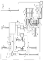
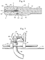
- the edger H of the invention includes a housing, as best shown in Figure 8, which encloses the components, while permitting operator access to the controls.
- Edger H includes a lower housing portion 10 to which upper housing portion 12 is hingedly connected.
- Upper portion 12 has a window 14 which may be opened by means of hinges 16 to permit operator access to the interior of the housing.
- Switch 18 is secured to window 14 and pivotal therewith, and prevents operation of edger H while the window 14 is in the raised position.
- Control panel C is mounted to a vertical portion of upper portion 12 and provides access by the optician to various controls, collectively 19, used in the invention.
- the edger H preferably is a three-axis dry edger, such as the Horizon® III edger manufactured and sold by National Optronics, Inc., the assignee hereof.
- the edger H has a base plate 20, as best shown in Figure 1, to which tables 22 and 24 are mounted for movement perpendicular to each other.
- Rails 26 and 28 are secured to base 20 and extend in parallel in a first direction relative to base 20.
- First table 22 is slidably mounted to rails 26 and 28 for movement therealong in the first direction.
- Servomotor drive 30 is mounted to base 20 adjacent rail 26, and is operably connected to rotary screw 32 for causing controlled rotation thereof.
- Bracket 34 is secured to first table 22 along the forward edge thereof. Bracket 34 incorporates a ball nut threadedly engaged with rotary screw 32, so that rotation of screw 32 causes corresponding displacement of the ball nut and hence of bracket 34 and table 22.
- servomotor drive 30, rotary screw 32, and the ball nut of bracket 34 provide precise positioning of the table 22 relative to the base 20, although other types of drives may be used in place of servomotor 30.
- the servomotor drives disclosed herein provide position feedback data, so that the location of the component of interest is always known with a high degree of accuracy.
- Servomotor drive 36 is mounted to and carried by table 22, and is operably connected to transmission 38 through motor coupling 40.
- Shaft 42 extends from transmission 38 in a direction transverse to the first direction defined by rails 26 and 28. Shaft 42 is controllably rotated with precision because of servomotor drive 36 acting through transmission 38.
- Clamp assembly 44 is secured to the end of shaft 42, is rotatable therewith, and is adapted for engagement with an edging block removably secured to lens blank to be edged.
- Pneumatic lens clamp cylinder 46 is secured to first table 22 above drive 36, and the extensible piston thereof is operably engaged with arm 48 for causing movement thereof.
- Arm 48 carries second clamp assembly 50 which is adapted for engaging a lens blank. Actuation of clamp cylinder 46 by the optician through one of the controls 19 causes displacement of clamp assembly 50 either toward or away from clamp assembly 44, thereby clamping or releasing a lens blank.
- a block to a surface thereof, such as by the 3M Leap® System or as disclosed in U.S. Patent 2,982,061.
- the block is releasably secured to clamp assembly 44 so that rotation of clamp assembly 44 by shaft 42 causes corresponding rotation of the lens blank about the axis of shaft 42. Because of the precision rotation accomplished by servomotor drive 36 and its feedback position data, then the angular position of the clamped lens blank is known by the control system of edger H.
- High speed motor 52 is mounted to second table 24, and has a rotary shaft 54.
- the motor 52 preferably rotates shaft 54 at a speed of 20,000 rpm or more in order to permit the dry edging process to proceed.
- Tool T is mounted to shaft 54, and is rotatable therewith in order for edging, polishing, and safety beveling the lens blank as will be further described.
- Rails 56 and 58 are secured to base 20 and extend in a second direction perpendicular to the first direction defined by rails 26 and 28.
- Second table 24 is slidably mounted to the rails 56 and 58 for movement in the second direction defined thereby.
- Servomotor drive 60 is secured to base 20, and drives rotary screw 62.
- Bracket 64 is secured to second table 24 and has a ball nut threadedly engaged with screw 62, so that rotation of screw 62 by motor 60 will cause corresponding displacement of bracket 64 and hence of second table 24.
- Water supply 66 is operably associated with base 20, and has a resilient supply line 68, such as provided by flexible rubber tubing, leading to spray nozzle 70.
- Spray nozzle 70 is secured to bracket 64 by tubing or light pipe 72, thereby maintaining orientation of nozzle 70 relative to tool T as second table 24 slides on the rails 56 and 58.
- pumps and pressure controls are provided in conjunction with water supply 66 so that there is adequate water pressure for droplet formation by nozzle 70.
- Rectangular opening 74 is formed in base 20, as best shown in Figures 1 and 7.
- Chip chute 76 is mounted to table 24 through brackets or the like, and defines a plate partially closing opening 74.
- Aperture 78 is formed in chip chute 76 below tool T, as best shown in Figure 1.
- cowl 80 has a duct-like portion 82 fitted within aperture 78 of chip chute 76.
- Cowl 80 has a slot 84 providing an opening adjacent tool T for permitting a lens blank clamped between assemblies 44 and 50 to be brought into engagement with tool T through operation of servomotor drive 30.
- Vacuum line 86 is secured to duct 82 below chip chute 76 for applying a vacuum to cowl 80.
- Vacuum line 86 terminates at a vacuum source, such as provided by an industrial vacuum cleaner, and causes air, particulates, and water mist to be drawn through cowl 80 to the vacuum source. Because of opening 74, then the vacuum line 86 moves with table 24 as the table moves in response to operation of servomotor drive 60. Preferably the vacuum is sufficiently strong to cause air flow over tool T to be of such intensity that heating of tool T is minimized. Heat generation during the edging, polishing, and safety beveling steps is to be avoided, particularly with materials such as polycarbonate.
- Figure 9 illustrates in dotted line form the periphery 88 of a circular lens blank B. Also illustrated in Figure 9 in solid line is the periphery 90 that the blank B will achieve upon completion of the edging process.
- the notation "GC” in Figure 9 identifies the geometric center of the blank 88, with the designation "OC” identifying the optical center of the finished blank 90.
- the blank B usually will be rotated about its geometric center by the edger, even though the prescribed optical characteristics are to be achieved at the optical center.
- Tool T is a two-part combination tool incorporating a router R and a polishing hub or tool P.
- a router is a tool for cutting into or below a main surface, and usually operates at a high rotary speed such as provided by motor 52.
- Router R preferably is a two-bladed router.
- Router R is generally cylindrical, and has a body 92 incorporating a reduced diameter first end portion 94 for being secured to shaft, 54 through chuck 96.
- Router R has a second polishing tool contacting end portion incorporating an axially extending cylindrical projection 98 and an annular flat shoulder 100 extending from projection 98 to the periphery 106 of body 92.
- the router R is preferably manufactured from grade 303 stainless steel.
- Projection 98 has an internally threaded coaxial bore 102 extending into body 92 from the distal end of projection 98. Opening 104 is formed in shoulder 100, and extends axially inwardly parallel to bore 102 intermediate projection 98 and the periphery 106 of body 92.
- Blades 108 and 110 extend angularly outwardly from periphery 106 of enlarged diameter portion 112 of body 92. Each of blades 108 and 110 extends along enlarged portion 112 from shoulder 100 to approximatly the proximal end of enlarged diameter portion 112. Each of blades 108 and 110 has a V-shaped notch 114 and 116, respectively, adjacent shoulder 100. The notches 114 and 116 are spaced a common distance along periphery 106, and are aligned so that a single V-shaped bevel is formed on blank B about periphery 90. Each of the blades 108 and 110 is mounted within a recess 118 and is secured within the recess by fasteners 120, as best shown in Figures 2-5.
- the blades 108 and 110 may be replaced as needed. While we have disclosed V-notches 114 and 116, those skilled in the art will appreciate that the configuration and size of the notches may be other than as shown and, alternatively, that each of the blades may have a protrusion intended to form a groove in the blank B.
- the periphery 106 of the router R has a V-shaped groove 122 aligned with each of notches 114 and 116, as best shown in Figures 2-5.
- Groove 122 permits the notches 114 and 116 and therefore the blades 108 and 110, respectively, to be precisely oriented relative to the periphery 106.
- Each of the notches 114 and 116 has a common shape and configuration, thereby facilitating replacement of the blades and assuring that the resulting bevel has the size and shape predetermined thereby.
- Blank B is a polymeric cast blank having optical surfaces 124 and 126 providing the prescribed optical properties for the resulting eyeglass lens of Figure 9.
- the polishing tool P may be so used.
- the edging of the blank B by the router R or other edging tool, such as a grinding wheel, causes the resulting edge to have a smokey or distressed finish 128 as illustrated in Figure 10(a).
- the smokey finish 128 is undesirable for those frames in which the opening does not completely encircle the resulting lens.
- Use of the tool T of Figure 6 pursuant to the steps illustrated in Figures 2-5 causes the resulting edge 90 to have the polished finish 130 of Figure 10(b), and also the safety bevel 162 of Figure 10(c).
- the smokey finish 128 is believed to arise from microscopic score lines formed in the edge of blank B while being edged, such as by the blades 108 and 110. While the cutting surfaces of the blades 108 and 110 are quite precise, those skilled in the art understand that microscopic score lines may occur with all edging tools because of surface imperfections, vibrations, thermal stresses, and similar factors causing the resulting lens edge 129 to achieve the smokey or distressed configuration.
- the polishing tool P removes the microscopic score line creating the smokey finish, so that the resulting edge has the polished translucent appearance 130 of Figure 10(b).
- the polished appearance is necessary principally with those frames in which the opening does not completely encircle the lens.
- the combination tool T thus may be used not only when standard edging is to be performed, but also when a polished edge is desired.
- the dry edger H may therefore be used regardless of the edge finish desired, thus enhancing operating efficiency of the optician and avoiding the costs previously required for polishing in a subsequent or additional machine.
- Polishing tool P is generally cylindrical in configuration, and has an outer diameter corresponding to the diameter defined by the cutting edges between blades 108 and 110.
- Tool P has throughout the entirety of its lens contacting periphery a 600 grit diamond material bonded thereto, such as provided by Inland Diamond Company.
- the diamond bond D has a thickness of about 0.125 inches in order to accommodate wear, and provides an abrasive coating with numerous fine cutting edges which remove the score lines and surface imperfections creating the smokey finish of Figure 10(a).
- the diamond bond D causes the polishing function to be implemented by the polishing tool P as the tool T is rotated by the motor 52. While we prefer 600 grit diamond bonded in a bronze-iron matrix, the grit could be finer or coarser depending upon the finish desired. In addition, the diamond could be plated onto the tool P.
- Polishing tool P has a router engaging end portion comprising a first bore 132 sized and configured to receive projection 98, and a radially outwardly extending flat shoulder 134 mating with shoulder 100 of router R, as best shown in Figure 6.
- Bore 136 extends through shoulder 134, and is aligned with opening 104 for receiving pin 138 therein.
- Pin 138 is received within the aligned coaxial bores 136 and 104 in order position the polishing tool P relative to the router R, and for preventing rotation therebetween during assembly.
- the pin 138 preferably is formed of a metallic material, and is removable from the bores 136 and 104 in the event the polishing tool P and router R need to be separated.
- Bolt 140 extends through bore 142 in polishing tool P.
- Bolt 140 has a head 144 received within opening 146.
- Bolt 140 has a threaded end 148 received within threaded bore 102 for securing the polishing tool P to the router R.
- V-notch or groove 150 is formed about the periphery 152 of polishing tool P intermediate the ends thereof.
- V-notch 150 has the same size and configuration as the notches 114 and 116 of the blades 108 and 110, respectively, in order to cause a bevel of the same size and configuration to be formed when the polishing tool P is used to polish the lens blank B.
- the V-notch 150 extends continuously about the periphery 152, as illustrated in Figures 2-5.
- notch 150 can be any desired size and configuration, preferably matching the size and configuration of notches 114 and 116.
- Chamfer 154 extends angularly from periphery 152 to distal end 156, preferably at an angle of 45°.
- the chamfer 154 provides an angled surface which breaks the sharp corner 160, best shown in Figure 10(b), formed at the intersection between surface 124 and the edge 90 of the resulting lens.
- the corner 160 is adjacent the wearer, and thus breaking that corner into the angled shape 162 of Figure 10(c) promotes safety by reducing the possibility that the wearer may become cut if contacted by that corner. Additionally, corner 160 may be broken to enhance the safety of the optician when installing the blank B into the eyeglass frame.
- Chamfer 154 extends forwardly and angularly from the periphery 152 toward the axis of rotation. The chamfer 154 terminates at flat distal end 156.
- Figures 2-3 illustrate use of the router R for either bevel edging the blank B and/or bevel edging the blank B for further processing with polishing tool P.
- the edger H causes the edge 88 of the blank B to engage the router R through cooperative operation of servomotor drives 30 and 60.
- the edge 88 of blank B initially contacts the blades 108 and 110 intermediate the V-notches 114 and 116 and the proximal end of the blades in order to edge or shape the periphery 88 to a first size and configuration.
- servomotor drives 30 and 60 causes their associated tables and hence the blank B and the tool T to move so that the lens blank B achieves a first desired shape and size.
- the tool T is shifted by servomotor drive 60 so that the periphery 88 of the blank B is engaged by the V-notches 114 and 116, thus forming bevel 158 thereabout, as best shown in Figure 3.
- the blades 108 and 110 when used for standard bevel edging, edge the blank to the finished size, so that the bevel 158 may be snapped into the corresponding groove in the frame opening.
- the servomotor drive 30 controls the servomotor drive 30 so that the diameter of the blank B, after engagement with the router R, is approximatly 0.40 millimeters larger than would be the final size if polishing were not to occur.
- the bevel 158 is also slightly larger. The somewhat larger diameter size is utilized because the diamond bond D removes material during polishing, and the amount of material removed needs to be taken into account. Should the diameter of the lens and the bevel 158 not be larger, then the polishing tool P would not be able to remove the score lines. This larger size is automatically provided through operation of servomotor drive 30, such as by the optician operating one of the controls 19 indicating that the edge is to be polished. The blank B should not be too much larger, however, because the polishing tool P removes material less quickly than router R.
- the servomotor drive 60 shifts the tool T to bring the thus produced distressed edge 128 into operative engagement with the polishing hub P, as best shown in Figure 4.
- the bevel 158 is positioned within the V-notch 150 and the periphery 128 of the blank B engaged with the diamond coated periphery 152.
- the tool T continues to be rotated at high speed by the motor 52, thus causing the diamond particles of the diamond bond D to remove the score lines causing the smokey surface 128, while also reducing the blank B to the finished shape and size.
- the nozzle 70 is on one side of the tool T and the cowl 80 on the opposite side, as best shown in Figures 1 and 7.
- the water supplied from source 60 acts as a lubricant, while also maintaining the temperature of the polishing tool P at a reduced level.
- the water spray droplets keep the tool and the blank relatively cool, thus avoiding unnecessary softening of the lens material. While we prefer that water be supplied through the nozzle 70, other fluidic coolants/lubricants may be utilized.
- the vacuum applied to cowl 80 through line 86 continues to operate not only throughout the router steps of Figures 2-3, but also during the polishing and safety beveling steps of Figures 4-5.
- the vacuum not only causes the fines created during the edging steps to be removed from within the housing of edger H, but the fine water droplets from the nozzle 70 and material removed by tool P also become evacuated. Because the fine water droplets are removed through the cowl 80, then the electrical components within the housing H are protected.
- the sharp corner 160 is removed by engaging the corner 160 with the chamfer 154. Because the chamfer 154 also is coated with diamond bond D, then it likewise polishes the resulting angled surface 162. The blank B is then ready to be snapped into the frame.
Landscapes
- Engineering & Computer Science (AREA)
- Mechanical Engineering (AREA)
- Chemical & Material Sciences (AREA)
- Ceramic Engineering (AREA)
- Inorganic Chemistry (AREA)
- Grinding And Polishing Of Tertiary Curved Surfaces And Surfaces With Complex Shapes (AREA)
- Polishing Bodies And Polishing Tools (AREA)
Description
- The present invention relates to a combination tool for edging and finishing the edge of eyeglass lenses according to the preamble of claim 1, such a combination tool being known from DE-U-87 11 265. Moreover, the present invention relates to a machine and a method using such a combination tool according to the preambles of claims 15 and 23.
- Many eyeglass lenses are manufactured today from polymeric materials, including polycarbonate material. Polymeric or plastic lenses are preferred by consumers in part because of their reduced weight, which increases user comfort when the eyeglasses need to be worn for an extended period. The lens blank is frequently cast in circular configuration, so that each blank needs to be edged, or shaped, to size in order to thereafter be mounted in the frame which has been selected. A further requirement is that a safety bevel be formed about the lens, particularly adjacent the wearer.
- Eyeglass frames have two spaced openings in which the finished lenses are mounted. The lens openings come in any number of sizes and configurations. Because there is no standard shape or size, nor a standard prescription, then the optician must shape each lens in a machine, known as an edger, preparatory to fitting the lens into the frame opening.
- The frame openings frequently have a bevel or a groove which interfits with a complementarily shaped groove or bevel, respectively, formed about the peripheral edge of the lens. The interfit between the complementary bevel and groove helps to secure the lens within the opening, thereby preventing removal as otherwise could occur. The edging machine forms the bevel or groove about the lens. The position of the bevel or groove is not necessarily fixed relative to the front or back surfaces of the lens, so the edging machine may need to take into account not only formation of the bevel or groove but also where that bevel or groove is to be positioned intermediate the lens surfaces.
- Some eyeglass frames have openings which do not completely encircle the lens. The bevel or groove is still provided in order to snap into the frame position, and the bevel or groove is continuous about the lens edge. When a lens is edged, the resulting edge will frequently have a smokey appearance caused by microscopic grooves scored into the edge by the grinding or cutting tool. The smokey finish is undesirable for those frames which have an opening not completely encircling the lens, and the smokey finish should be removed. Polishing is one technique used to remove this smokey finish in order for the finished lens to be acceptable to the user.
- The lens edge may be polished through various means in order to remove the smokey finish. Removal of the lens from the edger to permit polishing on a subsequent machine is inconvenient, both because of increased cost and the possibility of loss, damage, or the like, to the lens. Polishing is one of the last steps prior to placing the lens into the frame, so damage to the lens is to be avoided because of the costs already accrued in forming the lens.
- Edging of the lens, whether made of glass or polymeric material, can result in a sharp corner at the intersection of the inner surface and the peripheral edge. The sharp corner may present a safety concern, and therefore should be removed. A bevel may be ground about the lens in order to remove the sharp corner, thus forming an angled surface known as a safety bevel.
- DE-U-87 11 265 discloses a combination tool which may be used in the production of an eyeglass lens. The combination tool known from this publication comprises a chamfer body having a peripherally disposed and axially extending cutter portion and an axially extending grinding tool secured to said body and rotatable therewith. The grinding tool consists of a first section for pre-grinding the lens, a second section, comprising a V-shaped groove for shaping the edge of the lens, and a third section for finishing the grinding process. In use, the periphery of a lens is at first machined by a cutter tool and then smoothed out and equalized with the first and third section of the grinding tool. Moreover, facetting is carried out with second V-shaped section.
- It is the object of the invention, to provide a combination tool of the known kind, which is simple in construction while maintaining good machining results and allows complete machining of an eyeglass lens.
- To solve this object the combination tool of the above mentioned kind according to the present invention is provided with the characterizing features of claim 1; a machine with the features of claim 15 and a process with the features of claim 23 are provided as well. According to the present invention the cutter portions of the cutter body of the combination tool have notches therein, so that both the shaping of the lens and the shaping of the lens-edge may be performed in one cutting process. Since in such a cutting process the workpiece may be machined with a very high accuracy, it is only necessary to polish the cut lenses without the necessity of a further machining step, i.e. a grinding step, therebetween. Thus, the finishing tool according to the present invention does not need to have sections with different abrasive coatings, i.e. rough, fine and bevelling grids, so that the polishing tool may be of simple construction.
- Moreover, since the polishing tool has a chamfer at its terminal end, a lens may be edged and finished completely with a combination tool of the present invention, thus avoiding the need to remove the lens from the edger for safety bevelling and accordingly minimizing handling and damage costs.
- According to a preferred embodiment a tool containing has an annular radially extending shoulder and an axially extending projection. A bore extends through the shoulder into the body, and the bore is intermediate the projection and the periphery of the body. A threaded bore extends into the projection. The polishing tool has a distal end portion and an oppositely disposed body contacting portion. The body contacting portion includes an annular shoulder and first and second bores, the first bore sized and configured to accept the projection and the second bore sized and configured to correspond to the body shoulder bore. A third bore extends axially through the polishing tool from the distal end portion to the first bore. A bolt extends through the first and third bores, and has a threaded end portion received within the threaded bore for securing the body and the tool. A pin is positioned within the shoulder bore and the second bore for aligning the polishing tool relative to the body.
- Preferred embodiments of the invention are explained in the subclaims and in the following description of some embodiments with reference to the accompanying drawing.
- The above and other objects and novel features of the present invention will become apparent from the following detailed description of the preferred embodiment of the invention illustrated in the accompanying drawings wherein:
- Figure 1 is a plan view, partially in schematic, of the edger of the invention;
- Figure 2 is an elevational view partially in fragmentary section of the combination tool of the invention edging a lens blank;
- Figure 3 is an elevational view of the tool and blank of Figure 2 with a Level being formed on the edge of the lens blank;
- Figure 4 is an elevational view of the tool and blank of Figure 3 polishing the edge of the lens blank;
- Figure 5 is an elevational view of the tool and polished blank of Figure 4 during the formation of a safety bevel about a corner on the lens blank;
- Figure 6 is a cross-sectional view of the combination tool of the invention;
- Figure 7 is a fragmentary elevational view partially in section taken along the line 7-7 of Figure 1 and viewed in the direction of the arrows;
- Figure 8 is a perspective view of the enclosure of the edger of the invention;
- Figure 9 is a schematic view of a lens blank and the lens to be formed therefrom;
- Figure 10(a) is a fragmentary elevational view of an edged lens blank having a distressed finish;
- Figure 10(b) is a fragmentary elevational view of the lens blank of Figure 10(a) having a polished finish; and
- Figure 10(c) is a fragmentary elevation view of the lens blank of Figure 10(b) with a safety bevel.
-
- The edger H of the invention includes a housing, as best shown in Figure 8, which encloses the components, while permitting operator access to the controls. Edger H includes a
lower housing portion 10 to whichupper housing portion 12 is hingedly connected.Upper portion 12 has awindow 14 which may be opened by means ofhinges 16 to permit operator access to the interior of the housing.Switch 18 is secured towindow 14 and pivotal therewith, and prevents operation of edger H while thewindow 14 is in the raised position. Control panel C is mounted to a vertical portion ofupper portion 12 and provides access by the optician to various controls, collectively 19, used in the invention. - The edger H preferably is a three-axis dry edger, such as the Horizon® III edger manufactured and sold by National Optronics, Inc., the assignee hereof. The edger H has a
base plate 20, as best shown in Figure 1, to which tables 22 and 24 are mounted for movement perpendicular to each other. We prefer that the edger be a three-axis edger, because a three-axis edger does not require mechanical patterns. -
Rails base 20 and extend in parallel in a first direction relative tobase 20. First table 22 is slidably mounted torails base 20adjacent rail 26, and is operably connected torotary screw 32 for causing controlled rotation thereof.Bracket 34 is secured to first table 22 along the forward edge thereof.Bracket 34 incorporates a ball nut threadedly engaged withrotary screw 32, so that rotation ofscrew 32 causes corresponding displacement of the ball nut and hence ofbracket 34 and table 22. Those skilled in the art will understand that the combination ofservomotor drive 30,rotary screw 32, and the ball nut ofbracket 34 provide precise positioning of the table 22 relative to thebase 20, although other types of drives may be used in place ofservomotor 30. The servomotor drives disclosed herein provide position feedback data, so that the location of the component of interest is always known with a high degree of accuracy. - Servomotor drive 36 is mounted to and carried by table 22, and is operably connected to
transmission 38 throughmotor coupling 40.Shaft 42 extends fromtransmission 38 in a direction transverse to the first direction defined byrails Shaft 42 is controllably rotated with precision because ofservomotor drive 36 acting throughtransmission 38.Clamp assembly 44 is secured to the end ofshaft 42, is rotatable therewith, and is adapted for engagement with an edging block removably secured to lens blank to be edged. - Pneumatic
lens clamp cylinder 46 is secured to first table 22 abovedrive 36, and the extensible piston thereof is operably engaged witharm 48 for causing movement thereof.Arm 48 carriessecond clamp assembly 50 which is adapted for engaging a lens blank. Actuation ofclamp cylinder 46 by the optician through one of thecontrols 19 causes displacement ofclamp assembly 50 either toward or away fromclamp assembly 44, thereby clamping or releasing a lens blank. Those skilled in the art appreciate that edging of a lens requires the application of a block to a surface thereof, such as by the 3M Leap® System or as disclosed in U.S. Patent 2,982,061. The block is releasably secured to clampassembly 44 so that rotation ofclamp assembly 44 byshaft 42 causes corresponding rotation of the lens blank about the axis ofshaft 42. Because of the precision rotation accomplished byservomotor drive 36 and its feedback position data, then the angular position of the clamped lens blank is known by the control system of edger H. -
High speed motor 52 is mounted to second table 24, and has arotary shaft 54. Themotor 52 preferably rotatesshaft 54 at a speed of 20,000 rpm or more in order to permit the dry edging process to proceed. Tool T is mounted toshaft 54, and is rotatable therewith in order for edging, polishing, and safety beveling the lens blank as will be further described. -
Rails base 20 and extend in a second direction perpendicular to the first direction defined byrails rails base 20, and drivesrotary screw 62.Bracket 64 is secured to second table 24 and has a ball nut threadedly engaged withscrew 62, so that rotation ofscrew 62 bymotor 60 will cause corresponding displacement ofbracket 64 and hence of second table 24. Because of the precision control provided byservomotor drive 60,rotary screw 62, and the ball nut ofbracket 64, then precise positioning of tool T relative to a lens blank clamped between and rotated byclamp assemblies -
Water supply 66 is operably associated withbase 20, and has aresilient supply line 68, such as provided by flexible rubber tubing, leading tospray nozzle 70. Spraynozzle 70 is secured tobracket 64 by tubing orlight pipe 72, thereby maintaining orientation ofnozzle 70 relative to tool T as second table 24 slides on therails water supply 66 so that there is adequate water pressure for droplet formation bynozzle 70. -
Rectangular opening 74 is formed inbase 20, as best shown in Figures 1 and 7.Chip chute 76 is mounted to table 24 through brackets or the like, and defines a plate partially closingopening 74.Aperture 78 is formed inchip chute 76 below tool T, as best shown in Figure 1. As best shown in Figure 7,cowl 80 has a duct-like portion 82 fitted withinaperture 78 ofchip chute 76.Cowl 80 has aslot 84 providing an opening adjacent tool T for permitting a lens blank clamped betweenassemblies servomotor drive 30.Vacuum line 86 is secured toduct 82 belowchip chute 76 for applying a vacuum tocowl 80.Vacuum line 86 terminates at a vacuum source, such as provided by an industrial vacuum cleaner, and causes air, particulates, and water mist to be drawn throughcowl 80 to the vacuum source. Because of opening 74, then thevacuum line 86 moves with table 24 as the table moves in response to operation ofservomotor drive 60. Preferably the vacuum is sufficiently strong to cause air flow over tool T to be of such intensity that heating of tool T is minimized. Heat generation during the edging, polishing, and safety beveling steps is to be avoided, particularly with materials such as polycarbonate. - Those skilled in the art recognize that an eyeglass lens blank frequently is provided in the form of a cast circular blank. Figure 9 illustrates in dotted line form the
periphery 88 of a circular lens blank B. Also illustrated in Figure 9 in solid line is theperiphery 90 that the blank B will achieve upon completion of the edging process. The notation "GC" in Figure 9 identifies the geometric center of the blank 88, with the designation "OC" identifying the optical center of the finished blank 90. The blank B usually will be rotated about its geometric center by the edger, even though the prescribed optical characteristics are to be achieved at the optical center. - Tool T, as best shown in Figures 2-6, is a two-part combination tool incorporating a router R and a polishing hub or tool P. Those skilled in the art understand that a router is a tool for cutting into or below a main surface, and usually operates at a high rotary speed such as provided by
motor 52. Router R preferably is a two-bladed router. - Router R, as best shown in Figure 6, is generally cylindrical, and has a
body 92 incorporating a reduced diameterfirst end portion 94 for being secured to shaft, 54 throughchuck 96. Router R has a second polishing tool contacting end portion incorporating an axially extendingcylindrical projection 98 and an annularflat shoulder 100 extending fromprojection 98 to theperiphery 106 ofbody 92. The router R is preferably manufactured from grade 303 stainless steel.Projection 98 has an internally threadedcoaxial bore 102 extending intobody 92 from the distal end ofprojection 98.Opening 104 is formed inshoulder 100, and extends axially inwardly parallel to bore 102intermediate projection 98 and theperiphery 106 ofbody 92. -
Blades periphery 106 ofenlarged diameter portion 112 ofbody 92. Each ofblades enlarged portion 112 fromshoulder 100 to approximatly the proximal end ofenlarged diameter portion 112. Each ofblades notch adjacent shoulder 100. Thenotches periphery 106, and are aligned so that a single V-shaped bevel is formed on blank B aboutperiphery 90. Each of theblades recess 118 and is secured within the recess byfasteners 120, as best shown in Figures 2-5. Because of thefasteners 120, then theblades notches - The
periphery 106 of the router R has a V-shapedgroove 122 aligned with each ofnotches notches blades periphery 106. Each of thenotches - Blank B, as best shown in Figures 2-5, is a polymeric cast blank having
optical surfaces distressed finish 128 as illustrated in Figure 10(a). The smokey finish 128 is undesirable for those frames in which the opening does not completely encircle the resulting lens. Use of the tool T of Figure 6 pursuant to the steps illustrated in Figures 2-5 causes the resultingedge 90 to have thepolished finish 130 of Figure 10(b), and also thesafety bevel 162 of Figure 10(c). The smokey finish 128 is believed to arise from microscopic score lines formed in the edge of blank B while being edged, such as by theblades blades lens edge 129 to achieve the smokey or distressed configuration. - The polishing tool P removes the microscopic score line creating the smokey finish, so that the resulting edge has the polished
translucent appearance 130 of Figure 10(b). The polished appearance is necessary principally with those frames in which the opening does not completely encircle the lens. The combination tool T thus may be used not only when standard edging is to be performed, but also when a polished edge is desired. The dry edger H may therefore be used regardless of the edge finish desired, thus enhancing operating efficiency of the optician and avoiding the costs previously required for polishing in a subsequent or additional machine. - Polishing tool P, as best shown in Figures 2-6, is generally cylindrical in configuration, and has an outer diameter corresponding to the diameter defined by the cutting edges between
blades motor 52. While we prefer 600 grit diamond bonded in a bronze-iron matrix, the grit could be finer or coarser depending upon the finish desired. In addition, the diamond could be plated onto the tool P. - Polishing tool P has a router engaging end portion comprising a
first bore 132 sized and configured to receiveprojection 98, and a radially outwardly extending flat shoulder 134 mating withshoulder 100 of router R, as best shown in Figure 6.Bore 136 extends through shoulder 134, and is aligned with opening 104 for receiving pin 138 therein. Pin 138 is received within the alignedcoaxial bores bores -
Bolt 140 extends throughbore 142 in polishingtool P. Bolt 140 has ahead 144 received within opening 146.Bolt 140 has a threaded end 148 received within threadedbore 102 for securing the polishing tool P to the router R. - V-notch or groove 150 is formed about the
periphery 152 of polishing tool P intermediate the ends thereof. V-notch 150 has the same size and configuration as thenotches blades notch 150 extends continuously about theperiphery 152, as illustrated in Figures 2-5. As withnotches notches -
Chamfer 154 extends angularly fromperiphery 152 todistal end 156, preferably at an angle of 45°. Thechamfer 154 provides an angled surface which breaks thesharp corner 160, best shown in Figure 10(b), formed at the intersection betweensurface 124 and theedge 90 of the resulting lens. Thecorner 160 is adjacent the wearer, and thus breaking that corner into theangled shape 162 of Figure 10(c) promotes safety by reducing the possibility that the wearer may become cut if contacted by that corner. Additionally,corner 160 may be broken to enhance the safety of the optician when installing the blank B into the eyeglass frame.Chamfer 154 extends forwardly and angularly from theperiphery 152 toward the axis of rotation. Thechamfer 154 terminates at flatdistal end 156. - Figures 2-3 illustrate use of the router R for either bevel edging the blank B and/or bevel edging the blank B for further processing with polishing tool P. Should a standard bevel edge be desired for blank B, then the edger H causes the
edge 88 of the blank B to engage the router R through cooperative operation of servomotor drives 30 and 60. As best shown in Figure 2, theedge 88 of blank B initially contacts theblades notches periphery 88 to a first size and configuration. Those skilled in the art will appreciate that the control provided by servomotor drives 30 and 60 causes their associated tables and hence the blank B and the tool T to move so that the lens blank B achieves a first desired shape and size. After the initial size and shape have been achieved, then the tool T is shifted byservomotor drive 60 so that theperiphery 88 of the blank B is engaged by the V-notches bevel 158 thereabout, as best shown in Figure 3. Because of the precision control realizable through theservomotor drive 60 and because the angular position of the blank B is known about its axis of rotation fromservomotor drive 36, then the position of thebevel 158 relative to the front andrear surfaces bevel 158, as best shown in Figure 3, theblades bevel 158 may be snapped into the corresponding groove in the frame opening. - Should it be desirable to polish the edge of blank B, then we control the
servomotor drive 30 so that the diameter of the blank B, after engagement with the router R, is approximatly 0.40 millimeters larger than would be the final size if polishing were not to occur. Thebevel 158 is also slightly larger. The somewhat larger diameter size is utilized because the diamond bond D removes material during polishing, and the amount of material removed needs to be taken into account. Should the diameter of the lens and thebevel 158 not be larger, then the polishing tool P would not be able to remove the score lines. This larger size is automatically provided through operation ofservomotor drive 30, such as by the optician operating one of thecontrols 19 indicating that the edge is to be polished. The blank B should not be too much larger, however, because the polishing tool P removes material less quickly than router R. - After the blank B has been edged to the somewhat larger size described above, then the
servomotor drive 60 shifts the tool T to bring the thus produceddistressed edge 128 into operative engagement with the polishing hub P, as best shown in Figure 4. Thebevel 158 is positioned within the V-notch 150 and theperiphery 128 of the blank B engaged with the diamond coatedperiphery 152. The tool T continues to be rotated at high speed by themotor 52, thus causing the diamond particles of the diamond bond D to remove the score lines causing thesmokey surface 128, while also reducing the blank B to the finished shape and size. - We have found it advantageous to spray water at the tool T through the
nozzle 70 during the polishing step of Figure 4. Thenozzle 70 is on one side of the tool T and thecowl 80 on the opposite side, as best shown in Figures 1 and 7. The water supplied fromsource 60 acts as a lubricant, while also maintaining the temperature of the polishing tool P at a reduced level. We have found that the diamond bond D does not become occluded with the material removed from the blank B, such as could occur if the blank B were to achieve an elevated temperature and become soft. The water spray droplets keep the tool and the blank relatively cool, thus avoiding unnecessary softening of the lens material. While we prefer that water be supplied through thenozzle 70, other fluidic coolants/lubricants may be utilized. - The vacuum applied to cowl 80 through
line 86 continues to operate not only throughout the router steps of Figures 2-3, but also during the polishing and safety beveling steps of Figures 4-5. We have found that the vacuum not only causes the fines created during the edging steps to be removed from within the housing of edger H, but the fine water droplets from thenozzle 70 and material removed by tool P also become evacuated. Because the fine water droplets are removed through thecowl 80, then the electrical components within the housing H are protected. - After the edge of the lens has been polished pursuant to Figure 4 of the invention and/or has been beveled according to Figure 3, then the
sharp corner 160 is removed by engaging thecorner 160 with thechamfer 154. Because thechamfer 154 also is coated with diamond bond D, then it likewise polishes the resultingangled surface 162. The blank B is then ready to be snapped into the frame.
Claims (24)
- A combination tool for edging and finishing the edge of eyeglass lenses, comprising an axially extending rotatable cutter body (92) having peripherally disposed and axially extending cutting means (108, 110) and an axially extending finishing tool (P) secured to said body (92) and rotatable therewith, said finishing tool (P) having a notch (150) formed therein and an abrasive coating applied thereto for finishing the lens edge (B), characterized in that the cutter body (92) is a router with first and second cutter portions (108, 110) as cutting means each having a notch (114, 116) therein for shaping the edge of a lense (B), that the notches (114, 116) of the cutter portions (108, 110) are equiaxially spaced along said body (92), and that the finishing tool (P) is a polishing tool (P) comprising a chamfer (154) extending about a terminal end thereof for applying a safety edge to the lense (B).
- Combination tool of claim 1, wherein said body (2) and said polishing tool (P) are each generally cylindrical, and said body (92) and said polishing tool (P) have a common diameter.
- Combination tool of claim 1 or 2, wherein said first and second cutter portions (108, 110) are diametrically opposed.
- Combination tool of any preceding claim, wherein each cutter portion is a blade (108, 110) removably secured to said body (92).
- Combination tool of any preceding claim, wherein said polishing tool (P) has a proximal end portion mated to said body (92) and a distal end portion, said distal end portion having the chamfer (154).
- Combination tool of claim 5, wherein said second notch (150) is disposed intermediate said chamfer (154) and said proximal end portion.
- Combination tool of any preceding claim, wherein said abrasive coating is bonded to said polishing tool (P) throughout and over the entirety thereof.
- Combination tool of any preceding claim, wherein said abrasive coating is diamond grid.
- Combination tool of any preceding claim, wherein each of said notches (114, 116, 150) is V-shaped.
- Combination tool of any preceding claim, wherein said notches (114, 116, 150) each have a common size and configuration.
- Combination tool of any preceding claim, wherein said second notch (150) is a continuous groove formed about said polishing tool (P).
- Combination tool of any preceding claim, whereinsaid body (92) has a tool contacting end portion and an oppositely disposed polishing tool contacting portion, which includes an axially extending portion (98) and an annular radially extending shoulder extending therefrom;a bore (104) extends through said shoulder (98) into said body (92), and said bore (104) is intermediate said projection (98) and the periphery of said body (92);a threaded bore (102) extends into said projection (98);the polishing tool (P) is secured to said body (92) and has a distal end portion and an oppositely disposed body contacting portion including an annular shoulder (134) and first and second bores (132, 100) and said first bore (132) is sized and configured to accept said projection (98) and second bore (100) sized and configured to correspond to said body shoulder bore (104);a third bore (142) extends axially through said polishing tool (P) from said distal end portion to said first bore (132);a bolt (140) extends through said first and third bores (132, 142) and has a threaded end portion (148) received within said body threaded bore (102) for securing said body (92) and polishing tool (P); anda pin (138) is positioned within said shoulder bore (104) and said second bore (100) for aligning said polishing tool (P) relative to said body (92).
- Combination tool of claim 12, wherein said third bore (142) has first and second portions, said first portion being proximate said distal end portion and having a diameter exceeding the diameter of said second portion; and said bolt (140) has a head (144), and said head (144) is received within said third bore first portion.
- Combination tool of claim 12 or 13, wherein said projection (98) is cylindrical.
- Machine for edging and polishing the edge of an eyeglass lens comprising a combination tool for edging and finishing the edge of eyeglass lenses, comprising an axially extending rotatable cutter body (92) having peripherally disposed and axially extending cutting means (108, 110) and an axially extending finishing tool (P) secured to said body (92) and rotatable therewith, said finishing tool (P) having a notch (150) formed therein and an abrasive coating applied thereto for finishing the lens edge (B), characterized in that the cutter body (92) is a router with first and second cutter portions (108, 110) each having a notch (114, 116) therein for shaping the edge of a lense (B), as cutting means the notches (114, 116) of the cutter portions (108, 110) being equiaxially spaced along said body (92), and that the finishing tool (P) is a polishing tool (P) comprising a chamfer (154) extending about a terminal end thereof for applying a safety edge to the lense (B).
- Machine of claim 15, wherein a nozzle (70) is disposed adjacent to and aligned with said polishing tool (P) for directing fluid thereto.
- Machine of claims 15 or 16, further comprisinga first table (22) movable in a first direction, and first drive means (30) for controllably moving said first table (22) in said first direction;a lens clamping and rotating assembly (44, 50) secured to said first table (22) and movable therewith, said assembly including means for controllably rotating a lens about a first axis extending generally transverse to said first direction;a second table (24) movable in a second direction perpendicular to said first direction and parallel to said first axis, and second drive means (52) for controllably moving said second table (24) in said second direction,wherein the combination tool is mounted to said second table (24) and movable therewith, and wherein the combination tool is rotatable on a second axis parallel to said first axis.
- Machine of claims 16 and 17, wherein the nozzle (70) is secured to said second table (24) and movable therewith.
- Machine of any of claims 15 to 18, further comprising a source of liquid in flow communication with said nozzle for causing liquid to be supplied thereto; said conduit including a portion disposed adjacent said tool.
- Machine of claim 19, wherein said conduit portion is disposed on a first side of said tool and said nozzle (70) is disposed on an opposite second side of said tool.
- Machine of any of claims 15 to 20, further comprising a vacuum source operably associated with said tool for capturing removed lens material and fluid.
- Machine of claim 21, wherein said vacuum source includes a conduit (86) secured to and movable with said second table (24).
- Method for edging and polishing the edge of an eyeglass lens comprising the steps ofproviding a lens blank (B) having an edge;rotating the blank (B) about the geometric axis thereof;engaging the edge with a rotary cutter and thereafter with a rotary abrasive coated finishing tool (P) coaxial with the rotary cutter,
characterized by the following steps:providing a tool according to claim 1;engaging the edge of the blank (b) with the notches (114, 116) provided in the first and second cutter portions (108, 110) of the rotatable cutter (R) to achieve a first distressed configuration having a bevel formed thereabout,engaging the edge thereafter with the notch (150) provided in the polish tool (P) so that the bevel is positioned within the notch (150) of the tool and thereby causing the edge and bevel to achieve a second polished configuration andapplying the safety edge to the lens by engagement of the lense edge with the chamfer (154) provided at a terminal end of the polishing tool (P). - Method of claim 23, including the step of directing a lubricant at the polishing tool (P) while the polishing tool (P) is engaged with the edge.
Applications Claiming Priority (2)
| Application Number | Priority Date | Filing Date | Title |
|---|---|---|---|
| US08/316,780 US5626511A (en) | 1994-10-03 | 1994-10-03 | Combination lens edger, polisher, and safety beveler, tool therefor and use thereof |
| US316780 | 2002-12-10 |
Publications (2)
| Publication Number | Publication Date |
|---|---|
| EP0705660A1 EP0705660A1 (en) | 1996-04-10 |
| EP0705660B1 true EP0705660B1 (en) | 1999-08-04 |
Family
ID=23230658
Family Applications (1)
| Application Number | Title | Priority Date | Filing Date |
|---|---|---|---|
| EP95114178A Expired - Lifetime EP0705660B1 (en) | 1994-10-03 | 1995-09-09 | Combination lens edger, polisher, and safety beveler, tool therefor and use thereof |
Country Status (5)
| Country | Link |
|---|---|
| US (2) | US5626511A (en) |
| EP (1) | EP0705660B1 (en) |
| CA (1) | CA2158299C (en) |
| DE (1) | DE69511198T2 (en) |
| ES (1) | ES2137429T3 (en) |
Families Citing this family (37)
| Publication number | Priority date | Publication date | Assignee | Title |
|---|---|---|---|---|
| US5626511A (en) * | 1994-10-03 | 1997-05-06 | National Optronics, Inc. | Combination lens edger, polisher, and safety beveler, tool therefor and use thereof |
| DE19804455C2 (en) * | 1998-02-05 | 2001-01-11 | Wernicke & Co Gmbh | Method and device for producing a facet on the edge of a spectacle lens |
| US6623339B1 (en) * | 1999-08-06 | 2003-09-23 | Hoya Corporation | Lens processing device, lens processing method, and lens measuring method |
| JP4360764B2 (en) * | 2000-04-28 | 2009-11-11 | 株式会社トプコン | Lens peripheral processing method, lens peripheral processing apparatus, and spectacle lens for spectacle lens |
| WO2002016076A1 (en) * | 2000-08-18 | 2002-02-28 | Tokyo Seimitsu Co., Ltd. | Sheet peripheral edge grinder |
| US7559837B1 (en) | 2000-09-01 | 2009-07-14 | Igt | Video gaming system with wild card system and bonus system |
| US7258611B2 (en) | 2002-02-28 | 2007-08-21 | Igt | Gaming device having free game bonus with a changing multiplier |
| CA2377849C (en) * | 2002-03-21 | 2012-01-03 | General Electric Canada Inc. | High power rotary transformer with bus duct assembly |
| JP2003300140A (en) * | 2002-04-08 | 2003-10-21 | Hoya Corp | Lens processing equipment |
| US7252591B2 (en) * | 2002-07-31 | 2007-08-07 | Igt | Gaming device having symbol stacks |
| US7666083B2 (en) * | 2002-09-11 | 2010-02-23 | Igt | Gaming device having a free spin game including an accumulated modifier |
| US6960134B2 (en) * | 2002-09-12 | 2005-11-01 | Igt | Alternative bonus games associated with slot machine |
| DE10255058A1 (en) * | 2002-11-25 | 2004-06-17 | Loh Optikmaschinen Ag | Process and device for edge processing of an optical lens made of plastic and combination tool therefor |
| US7090559B2 (en) * | 2003-11-19 | 2006-08-15 | Ait Industries Co. | Ophthalmic lens manufacturing system |
| DE202004004492U1 (en) * | 2004-03-19 | 2005-07-21 | Mader, Gerd | notching |
| US20060011617A1 (en) * | 2004-07-13 | 2006-01-19 | Ricardo Covarrubias | Automated laser cutting of optical lenses |
| US7029378B1 (en) | 2004-10-14 | 2006-04-18 | National Optronics, Inc. | Combination router-end mill cutter tool, edger with combination tool, and method of edging eyeglass lenses |
| US7198436B2 (en) * | 2004-10-14 | 2007-04-03 | National Optronics, Inc. | Multi-blade router tool, edger with multi-blade router tool, and method of edging eyeglass lenses |
| FR2884163B1 (en) * | 2005-04-07 | 2007-07-06 | Briot Internat Sa | OPTICAL GLASS GRINDING MACHINE WITH INCLINED FINISHING WHEEL AND CORRESPONDING OPTICAL GLASS |
| ATE407770T1 (en) * | 2006-05-12 | 2008-09-15 | Satisloh Gmbh | METHOD AND DEVICE FOR PRODUCING AN OPTICAL SURFACE ON A WORKPIECE, E.G. OPHTHALMIC LENSES |
| US7403346B2 (en) * | 2006-07-18 | 2008-07-22 | Nike, Inc. | Inclined-edged sports lens |
| US7392108B2 (en) * | 2006-08-29 | 2008-06-24 | National Optronics, Inc. | Method of controlling an edger device, machine programmed to edge an ophthalmic lens blank, and computer program |
| US20080096466A1 (en) * | 2006-10-18 | 2008-04-24 | Jeff Eisenberg | Method and apparatus for cooling lens edge during dry processing |
| US8137179B2 (en) * | 2006-11-08 | 2012-03-20 | Igt | Gaming device having expanding and rolling wild symbols |
| US7454264B2 (en) * | 2006-11-29 | 2008-11-18 | Kurt William Schaeffer | Method of beveling an ophthalmic lens blank, machine programmed therefor, and computer program |
| US8408990B2 (en) | 2008-11-14 | 2013-04-02 | Igt | Gaming system, gaming device, and method for providing benefit in a future play of a wagering game |
| JP5162640B2 (en) * | 2010-10-06 | 2013-03-13 | 川崎重工業株式会社 | Sheet glass conveying device and chamfering device equipped with the same |
| EP2537633B1 (en) * | 2011-06-24 | 2014-05-07 | Comadur S.A. | Bevel machining system |
| US9293014B2 (en) | 2012-03-12 | 2016-03-22 | Igt | Gaming device having persistently extending wild symbols |
| US9098847B2 (en) | 2013-03-08 | 2015-08-04 | Igt | Gaming system and method for providing a game including roaming wild symbols |
| US9098973B2 (en) | 2013-03-08 | 2015-08-04 | Igt | Gaming system and method for providing a game including roaming wild symbols |
| US20150065011A1 (en) * | 2013-08-28 | 2015-03-05 | Jonathan Mandelbaum | Diamond Cutting Tool for Plastic Ornamentation and Method Thereof |
| KR102547935B1 (en) * | 2016-06-24 | 2023-06-27 | 삼성디스플레이 주식회사 | Grinding device for substrate |
| US10307881B2 (en) | 2017-02-22 | 2019-06-04 | National Optronics, Inc. | Ophthalmic lens processing apparatus with improved user accessibility |
| CN112123084A (en) * | 2020-10-09 | 2020-12-25 | 宋庆忠 | Chamfering device for processing positive and negative pole pieces of lithium battery |
| CN113414650A (en) * | 2021-05-06 | 2021-09-21 | 郑慧彬 | Fastener processing equipment |
| KR20240059826A (en) * | 2022-10-27 | 2024-05-08 | 삼성디스플레이 주식회사 | Polishing apparatus |
Family Cites Families (25)
| Publication number | Priority date | Publication date | Assignee | Title |
|---|---|---|---|---|
| US1449266A (en) * | 1921-04-07 | 1923-03-20 | Edward W Clarke | Machine for grinding the edges of lenses |
| US2982061A (en) * | 1960-03-17 | 1961-05-02 | American Optical Corp | Lens blocking apparatus |
| US3828648A (en) * | 1973-01-18 | 1974-08-13 | J Geula | Plastic-lens cutter |
| GB1472282A (en) * | 1973-04-25 | 1977-05-04 | Hedelin L | Eyeglass lens grinding wheel and a method of grinding eyeglass lenses |
| US4171926A (en) * | 1978-04-21 | 1979-10-23 | American Optical Corporation | Lens cutter |
| US4459784A (en) * | 1978-11-13 | 1984-07-17 | Hernandez William D | Computer lens block and method of forging |
| FR2553323B1 (en) * | 1983-10-18 | 1986-07-25 | Essilor Int | METHOD AND MACHINE FOR BEVELING OR SLOTTING AN OPHTHALMIC LENS |
| FR2562829B1 (en) * | 1984-04-12 | 1986-06-13 | Briot Int | CONTROL DEVICE FOR LIFTING AND TRANSLATING THE TROLLEY OF AN OVERFLOWING AND BEVELING GLASSES OF GLASSES |
| JPS62241841A (en) * | 1986-04-15 | 1987-10-22 | Kiyokuei Kenma Kako Kk | Method for forming chamfered hole and tool therefor |
| US4909679A (en) * | 1986-10-08 | 1990-03-20 | National Optronics Inc. | Plastic lens edge beveler |
| DE8711265U1 (en) * | 1986-11-03 | 1987-10-08 | Wernicke & Co GmbH, 4000 Düsseldorf | Turning tool for edge processing of plastic spectacle lenses |
| DE8629226U1 (en) * | 1986-11-03 | 1986-12-18 | Wernicke & Co GmbH, 40231 Düsseldorf | Turning tool for edge processing of spectacle lens edges |
| FR2611560B1 (en) * | 1987-03-05 | 1992-10-02 | Briot Int | IMPROVEMENTS IN GRINDING AND BEVELING MACHINES FOR OPHTHALMIC LENSES |
| FR2614227B1 (en) * | 1987-04-22 | 1992-10-02 | Briot Int | PERFECTED GRINDER FOR OPHTHALMIC LENSES. |
| US4908996A (en) * | 1987-09-22 | 1990-03-20 | Abraxas, Incorporated | Method for machine polishing ophthalmic lenses to a translucent finish |
| JP2598089B2 (en) * | 1988-07-05 | 1997-04-09 | 株式会社トプコン | Eyeglass lens peripheral edge chamfering device |
| DE3841493A1 (en) * | 1988-12-09 | 1990-06-13 | Wernicke & Co Gmbh | Device for the edge-working of spectacle lenses |
| FR2644718A1 (en) * | 1989-03-23 | 1990-09-28 | Briot Internal | DEVICE FOR RE-CALIBRATING A MACHINE FOR GRINDING OPHTHALMIC GLASSES TO REPAIR THE WEAR OF THE WHEEL |
| DE9004305U1 (en) * | 1990-04-18 | 1990-07-26 | Weco Wernicke & Co GmbH, 4000 Düsseldorf | Device for edging spectacle lenses |
| US5158422A (en) * | 1991-03-01 | 1992-10-27 | National Optronics, Inc. | Method and apparatus for shaping and finishing lenses |
| US5410843B1 (en) * | 1991-05-16 | 1998-06-09 | Wernicke & Co Gmbh | Process for finishing the edge of corrective lenses made of plastic |
| JPH0639696A (en) * | 1992-07-24 | 1994-02-15 | Topcon Corp | Grinding method and grinding device of spectacle lens edge |
| JPH06226629A (en) * | 1993-02-05 | 1994-08-16 | Nikon Corp | Deodorizing device for automatic lens edger |
| US5711700A (en) * | 1994-02-22 | 1998-01-27 | Inland Diamond Products Co. | Process to edge and polish polycarbonate and CR 39 lenses with diamond wheels |
| US5626511A (en) * | 1994-10-03 | 1997-05-06 | National Optronics, Inc. | Combination lens edger, polisher, and safety beveler, tool therefor and use thereof |
-
1994
- 1994-10-03 US US08/316,780 patent/US5626511A/en not_active Expired - Lifetime
-
1995
- 1995-09-09 EP EP95114178A patent/EP0705660B1/en not_active Expired - Lifetime
- 1995-09-09 ES ES95114178T patent/ES2137429T3/en not_active Expired - Lifetime
- 1995-09-09 DE DE69511198T patent/DE69511198T2/en not_active Expired - Lifetime
- 1995-09-15 CA CA002158299A patent/CA2158299C/en not_active Expired - Lifetime
-
1997
- 1997-05-05 US US08/841,804 patent/US6203409B1/en not_active Expired - Lifetime
Also Published As
| Publication number | Publication date |
|---|---|
| US6203409B1 (en) | 2001-03-20 |
| EP0705660A1 (en) | 1996-04-10 |
| US5626511A (en) | 1997-05-06 |
| DE69511198D1 (en) | 1999-09-09 |
| CA2158299A1 (en) | 1996-04-04 |
| CA2158299C (en) | 2009-06-02 |
| DE69511198T2 (en) | 2000-01-27 |
| ES2137429T3 (en) | 1999-12-16 |
Similar Documents
| Publication | Publication Date | Title |
|---|---|---|
| CA2158299C (en) | Combination lens edger, polisher, and safety beveler, tool therefor, and use thereof | |
| US8931769B2 (en) | Device and method for deblocking optical workpieces, in particular spectacle lenses | |
| US9120196B2 (en) | Device for deblocking optical workpieces, in particular eyeglass lenses | |
| US8597080B2 (en) | Ophthalmic roughing wheel | |
| US7571526B2 (en) | Multi-blade router tool, edger with multi-blade router tool, and method of edging eyeglass lenses | |
| US5720649A (en) | Optical lens or lap blank surfacing machine, related method and cutting tool for use therewith | |
| US5711700A (en) | Process to edge and polish polycarbonate and CR 39 lenses with diamond wheels | |
| US10112280B2 (en) | Method for machining optical workpieces, in particular, plastic spectacle lenses | |
| EP1799399B1 (en) | Combination tool, edger and method of edging eyeglass lenses. | |
| US4322915A (en) | Apparatus for beveling glass | |
| CA2396284A1 (en) | System and method for ophthalmic lens manufacture | |
| US8597079B2 (en) | Abrasive wheel with closed profiles in cutting surface | |
| KR102309539B1 (en) | Composite diamond wheel system in lens processing machine | |
| CN114701078A (en) | A kind of lens milling and grinding system and its technological method | |
| EP3463732B1 (en) | Retruing of a grinding wheel using edm machine | |
| CA2500975A1 (en) | Method of machining a blank or a semifinished product | |
| EP1332013B1 (en) | Method of edge finishing an optical lens of polycarbonate or CR39 plastics with swarf clearance | |
| CN222958247U (en) | Five-axis grinding machine tool | |
| CN220007065U (en) | Auxiliary tool for machining small workpiece of grinding machine | |
| CN219542541U (en) | Cutter grinding machine convenient to maintain | |
| CN222537104U (en) | Grinding device for end mill | |
| CN220838117U (en) | Anti-shake circular arc milling cutter |
Legal Events
| Date | Code | Title | Description |
|---|---|---|---|
| PUAI | Public reference made under article 153(3) epc to a published international application that has entered the european phase |
Free format text: ORIGINAL CODE: 0009012 |
|
| AK | Designated contracting states |
Kind code of ref document: A1 Designated state(s): BE DE ES FR GB IT |
|
| 17P | Request for examination filed |
Effective date: 19960607 |
|
| 17Q | First examination report despatched |
Effective date: 19970915 |
|
| GRAG | Despatch of communication of intention to grant |
Free format text: ORIGINAL CODE: EPIDOS AGRA |
|
| GRAG | Despatch of communication of intention to grant |
Free format text: ORIGINAL CODE: EPIDOS AGRA |
|
| GRAH | Despatch of communication of intention to grant a patent |
Free format text: ORIGINAL CODE: EPIDOS IGRA |
|
| GRAH | Despatch of communication of intention to grant a patent |
Free format text: ORIGINAL CODE: EPIDOS IGRA |
|
| GRAA | (expected) grant |
Free format text: ORIGINAL CODE: 0009210 |
|
| AK | Designated contracting states |
Kind code of ref document: B1 Designated state(s): BE DE ES FR GB IT |
|
| REF | Corresponds to: |
Ref document number: 69511198 Country of ref document: DE Date of ref document: 19990909 |
|
| ITF | It: translation for a ep patent filed | ||
| ET | Fr: translation filed | ||
| REG | Reference to a national code |
Ref country code: ES Ref legal event code: FG2A Ref document number: 2137429 Country of ref document: ES Kind code of ref document: T3 |
|
| PLBQ | Unpublished change to opponent data |
Free format text: ORIGINAL CODE: EPIDOS OPPO |
|
| PLBI | Opposition filed |
Free format text: ORIGINAL CODE: 0009260 |
|
| PLBF | Reply of patent proprietor to notice(s) of opposition |
Free format text: ORIGINAL CODE: EPIDOS OBSO |
|
| 26 | Opposition filed |
Opponent name: LOH OPTIKMASCHINEN AG Effective date: 20000504 |
|
| PLBF | Reply of patent proprietor to notice(s) of opposition |
Free format text: ORIGINAL CODE: EPIDOS OBSO |
|
| PLBF | Reply of patent proprietor to notice(s) of opposition |
Free format text: ORIGINAL CODE: EPIDOS OBSO |
|
| PLBO | Opposition rejected |
Free format text: ORIGINAL CODE: EPIDOS REJO |
|
| APAC | Appeal dossier modified |
Free format text: ORIGINAL CODE: EPIDOS NOAPO |
|
| APAE | Appeal reference modified |
Free format text: ORIGINAL CODE: EPIDOS REFNO |
|
| APAC | Appeal dossier modified |
Free format text: ORIGINAL CODE: EPIDOS NOAPO |
|
| REG | Reference to a national code |
Ref country code: GB Ref legal event code: IF02 |
|
| PLBN | Opposition rejected |
Free format text: ORIGINAL CODE: 0009273 |
|
| STAA | Information on the status of an ep patent application or granted ep patent |
Free format text: STATUS: OPPOSITION REJECTED |
|
| 27O | Opposition rejected |
Effective date: 20010819 |
|
| APAH | Appeal reference modified |
Free format text: ORIGINAL CODE: EPIDOSCREFNO |
|
| PGFP | Annual fee paid to national office [announced via postgrant information from national office to epo] |
Ref country code: ES Payment date: 20100921 Year of fee payment: 16 Ref country code: BE Payment date: 20100617 Year of fee payment: 16 |
|
| PGFP | Annual fee paid to national office [announced via postgrant information from national office to epo] |
Ref country code: IT Payment date: 20100924 Year of fee payment: 16 |
|
| BERE | Be: lapsed |
Owner name: *NATIONAL OPTRONICS INC. Effective date: 20110930 |
|
| PG25 | Lapsed in a contracting state [announced via postgrant information from national office to epo] |
Ref country code: IT Free format text: LAPSE BECAUSE OF NON-PAYMENT OF DUE FEES Effective date: 20110909 |
|
| PG25 | Lapsed in a contracting state [announced via postgrant information from national office to epo] |
Ref country code: BE Free format text: LAPSE BECAUSE OF NON-PAYMENT OF DUE FEES Effective date: 20110930 |
|
| PG25 | Lapsed in a contracting state [announced via postgrant information from national office to epo] |
Ref country code: ES Free format text: LAPSE BECAUSE OF NON-PAYMENT OF DUE FEES Effective date: 20110910 |
|
| REG | Reference to a national code |
Ref country code: ES Ref legal event code: FD2A Effective date: 20130530 |
|
| PGFP | Annual fee paid to national office [announced via postgrant information from national office to epo] |
Ref country code: DE Payment date: 20140827 Year of fee payment: 20 |
|
| PGFP | Annual fee paid to national office [announced via postgrant information from national office to epo] |
Ref country code: GB Payment date: 20140923 Year of fee payment: 20 |
|
| PGFP | Annual fee paid to national office [announced via postgrant information from national office to epo] |
Ref country code: FR Payment date: 20140901 Year of fee payment: 20 |
|
| REG | Reference to a national code |
Ref country code: DE Ref legal event code: R071 Ref document number: 69511198 Country of ref document: DE |
|
| REG | Reference to a national code |
Ref country code: GB Ref legal event code: PE20 Expiry date: 20150908 |
|
| PG25 | Lapsed in a contracting state [announced via postgrant information from national office to epo] |
Ref country code: GB Free format text: LAPSE BECAUSE OF EXPIRATION OF PROTECTION Effective date: 20150908 |