EP0706946B1 - Verfahren und Vorrichtung zum Handhaben von Zuschnitt-Stapeln mit Banderolen - Google Patents
Verfahren und Vorrichtung zum Handhaben von Zuschnitt-Stapeln mit Banderolen Download PDFInfo
- Publication number
- EP0706946B1 EP0706946B1 EP19950115106 EP95115106A EP0706946B1 EP 0706946 B1 EP0706946 B1 EP 0706946B1 EP 19950115106 EP19950115106 EP 19950115106 EP 95115106 A EP95115106 A EP 95115106A EP 0706946 B1 EP0706946 B1 EP 0706946B1
- Authority
- EP
- European Patent Office
- Prior art keywords
- blanks
- stack
- knife
- wrapping band
- band
- Prior art date
- Legal status (The legal status is an assumption and is not a legal conclusion. Google has not performed a legal analysis and makes no representation as to the accuracy of the status listed.)
- Expired - Lifetime
Links
Images



Classifications
-
- B—PERFORMING OPERATIONS; TRANSPORTING
- B65—CONVEYING; PACKING; STORING; HANDLING THIN OR FILAMENTARY MATERIAL
- B65B—MACHINES, APPARATUS OR DEVICES FOR, OR METHODS OF, PACKAGING ARTICLES OR MATERIALS; UNPACKING
- B65B69/00—Unpacking of articles or materials, not otherwise provided for
- B65B69/0025—Removing or cutting binding material, e.g. straps or bands
-
- Y—GENERAL TAGGING OF NEW TECHNOLOGICAL DEVELOPMENTS; GENERAL TAGGING OF CROSS-SECTIONAL TECHNOLOGIES SPANNING OVER SEVERAL SECTIONS OF THE IPC; TECHNICAL SUBJECTS COVERED BY FORMER USPC CROSS-REFERENCE ART COLLECTIONS [XRACs] AND DIGESTS
- Y10—TECHNICAL SUBJECTS COVERED BY FORMER USPC
- Y10T—TECHNICAL SUBJECTS COVERED BY FORMER US CLASSIFICATION
- Y10T83/00—Cutting
- Y10T83/202—With product handling means
- Y10T83/2066—By fluid current
- Y10T83/207—By suction means
Definitions
- the invention relates to a method and a device for transporting Blank stacking as well as for cutting and removing one the band around the blank stack in the area of a band station through a knife, the knife in the area of an upright leg of the band between blanks of the blank stack and the banderole by relative movement of knives and cut stacks along the upright Thigh is cut.
- it is about the Transport of banderoles in connection with a packaging machine, preferably to a blank magazine Packaging machine.
- the invention further relates to a Device for performing the method.
- Blanks for the production of packaging from (thin) Cardboard, in particular for the production of hinged boxes (Hinge-lid packs) for cigarettes, are usually in prefabricated in a cardboard box factory and as a blank stack delivered. To secure the formation of the blank stacks, It is common practice to stack the blanks with one of these surrounding strip-shaped band made of paper, film or to provide the like. In the area of the packaging machine must then the band is cut and removed so that banderole-free blank stack of the packaging machine, in particular to a blank magazine of the same can be.
- the invention is concerned with handling by banderoles surrounding stack of blanks in the area of a packaging machine.
- the object of the invention is to cut through and removing the banderoles, in particular to accelerate without the risk of damage to Cutting exists.
- the method according to the invention is used to achieve this object characterized in that the knife in the upper region of the Upright leg between the top blanks of the blank stack introduced and cut the banderole in this area and that the thigh after separating down until it is pulled away from under the blank stack.
- the object is further achieved by the device according to claim 5.
- this is inventively pulled down, in such a way that after the First cut through the upright leg an upright, up and down movable wall down moved and then after pushing the stack of blanks the Overall banderole down by appropriate funding bodies is pulled away.
- the discharge conveyor is preferably a vertical conveyor with a platform to hold a stack of blanks.
- the embodiments of the drawings are about the handling of blank stacks 10 from blanks for the cigarette industry. It is elongated Cuts with the for the production of folding boxes (Hinge-Lid packs) characteristic contour. The cuts consist of thin cardboard.
- Each stack of blanks 10 is of a strip-like shape Banderole 11 surrounded.
- This is a finite, rectangular one Hose piece formed with opposite one another upright legs 12, 13 and upper and lower Cross bars 14, 15.
- the band 11 is made of a finite Material strips formed with a glued overlap 16 in the region of the leg 13.
- the band 11 is made preferably made of paper (kraft paper), but can also be made of a film or other suitable material consist. It is advantageous if the band 11 through Coating or other measures largely airtight is trained.
- 10 are on a pallet (not shown).
- a suitable lifting conveyor e.g. a Robot with lifting head, sets the blank stack 10 individually or in groups to form a continuous row 17 on a feed conveyor 18. This is as a belt conveyor educated.
- the feed conveyor 18 can be driven in cycles. It transports the blank stack 10 successively in a banderole station 19. In the area of the same the band 11 severed and eliminated. The exempted from the band 11 Blank stacks 10 are transferred to a conveyor, the blank stack 10 for further processing feeds.
- the banderole station 19 part of a packaging machine 20 for producing Hinged boxes for cigarettes. Feeder 18 and banderole station 19 are in the area of the back of the packaging machine 20 positioned.
- the blank stack 10 is in the banderole station 19 promoted by the feed conveyor 18 on a run, namely on a plate 21.
- the blank stack 10 rests on this during the cutting of the band 11.
- an up and down movable cutting unit 22 positioned above the plate 21 or the blank stack 10 .
- the blade-like knife 23 becomes this Purposes in a horizontal plane relative to the blank stack 10 or moved to the band 11.
- the knife 23 is on a reciprocating knife holder 24 attached, like a sled on a guide rail 25 of the cutting unit 22 is displaceable.
- the elongated knife 23 or a cutting edge 26 of the same is at an acute angle to the direction of movement during the cutting process, ie directed towards the guide rail 25.
- the cutting unit is used to carry out a cutting process 22 through a lifting cylinder 27 to the cutting plane lowered.
- the knife 23 lies directly in one plane below the upper transverse leg 12 the band 11, such that the knife 23 between the upper Cutting the blank stack 10 moves and also with a section occurs between the blanks. It deals a few or just a cut, which lies above the parting plane of the knife 23.
- the knife holder 24 is used to carry out the separating cut moved along the guide rail 25.
- the knife 23 is initially outside the area of the band 11 between the upper blanks until the upright Leg 12 is detected and severed. The knife 23 slides during the cutting movement to the end of the blank stack.
- the preferably over the entire length of the blank stack 10 off-center on this stamp plate 29 has the additional effect that especially the upper ones Cut easily on the side facing the knife 23 to be fanned out. This is the introduction of the knife 23 in the area between the upper blanks.
- the severed sleeve 11 is then removed.
- the band 11 in the region of the leg 12 gripped by a holder.
- the blank stack 10 lies with the leg 12 of the sleeve 11 on the contact wall 31 (Fig. 3).
- the contact wall 31 is with holding members for detecting the Banderole 11 provided after cutting. It deals are several suction elements arranged side by side 32. These are positioned on the contact wall 31 that they grasp the separated leg 12 in the upper area.
- the contact wall 31 can be moved up and down in the vertical plane.
- the contact wall 31 is for this purpose with sliding guides 33 on two spaced, upright Guide rods 34 stored. These in turn are above and below with cross struts 35 on a fixed, upright support wall 36 attached.
- a rodless cylinder namely an upright linear cylinder 37 attached.
- a piston that can be moved up and down the same is connected to the slide guides 33.
- By the linear cylinder 37 is accordingly the contact wall 31 and removable.
- the blank stack 10 is now from the banderole station 19 moved out, with the severed band 11 retained or is promoted.
- the blank stack 10 reaches a conveyor without a sleeve 11.
- the blank stack 10 is trapped by the plate 21 from directly onto a platform 39 of a vertical conveyor 40 pushed.
- the one-sided on this vertical conveyor 40 stored platform extends during the recording of the blank stack 10 at the level of the plate 21.
- the transfer of the blank stack 10 from the plate 21 to the vertical conveyor 40 is carried out by a slide unit 41.
- this consists of two upright ones Driving rods 42, 43, which are from a sideways position 8 outside the movement path of the blank stack 10 by opposing transverse movement in between the blank stack 10 on the plate 21 on the one hand and the blank stacks 10 on the feed conveyor 18, on the other hand formed space 44 occur.
- This space 44 has been created in that the feed conveyor 18 after depositing the blank stack 10 on the Plate 21 is driven in the opposite direction, such that a return movement of the row 17 of the blank stack 10 takes place.
- the space 44 Entered driving rods 42, 43 support in a coordinated manner Way the conveying movement of the blank stack 10th from plate 21 to platform 39 during the downward movement the band 11.
- the driver rods 42, 43 are with sliders 45 transverse bars 46 slidable.
- the cross movement the driver rods 42, 43 is effected by cylinder 47.
- the slide unit 41 described so far is for implementation the thrust movement on one in the conveying direction extending linear cylinder 57 attached. This is positioned above the trajectory of the blank stack 10.
- the rods 46 are attached to a support 48, which in turn has a piston of the linear cylinder 57 connected is. Through this the driver rods 42, 43 in the push-off direction of the blank stack 10 with entrainment the same movable.
- the drive rods 42, 43 are out of range the band 11 on the blank stack 10 effective.
- a side loop 38 is created as a result of the push-off movement through the lower crosspiece 15 of the band. This will completely pulled down once the blank stack deposited on the conveyor or on the platform 39 is (Fig. 6).
- the vertical conveyor 40 assigned a holding member, which a Retains force on the blank stack 10 while the sleeve 11 is pulled off. It is about a pressure roller 58, which is from above on the blank stack 10 is lowered, in the present case in the area the band 11 or the leg 12.
- the pressure roller 58 is mounted on a bracket 59 and by a cylinder (not shown) movable into the pressing position (extended Lines in Figs. 6 and 8).
- the pressure roller is on a pivoted, two-armed lever 60 attached, at its free end the pressure cylinder engages.
- the pressure roller 58 causes the blank stack 10 in unchanged position on platform 39 is fixed while the banderole 11 is pulled down becomes.
- the blank stack 10 is transported away by the vertical conveyor 40.
- a monitoring body namely a light barrier 61. This gives away the stack of blanks 10 free when the banderole 11 is complete has been moved past the light barrier 61.
- the blank stacks 10 are used for further processing fed by the vertical conveyor 40 to a linear conveyor 52. This transports the blank stack 10 at an elevated level Level ("overhead") to the packaging machine 20. Here the blank stacks 10 are passed to blank magazines 53.
- the linear conveyor 52 in the present case consists of a horizontal conveyor track 54, on the blank stack 10 lie on. Lateral guides secure the stack of blanks 10 in this position.
- a floating carrier 55 detects the blank stack 10 on the back and slides it on the conveyor 54.
- the Driver 55 is by an elongated linear cylinder 56 driven. The blank stacks 10 are through the driver 55 from the platform 39 of the vertical conveyor 40 pushed off and directly onto the conveyor track 54 transfer.
Landscapes
- Engineering & Computer Science (AREA)
- Mechanical Engineering (AREA)
- Making Paper Articles (AREA)
- Control And Other Processes For Unpacking Of Materials (AREA)
Description
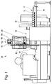
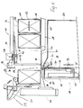
- Fig. 1
- eine Verpackungsmaschine in schematischer Darstellung mit einer Banderolen-Station in Rückansicht,
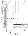
- Fig. 2
- die Banderolen-Station der Verpackungsmaschine gemäß Fig. 1 in schematischem Grundriß,
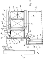
- Fig. 3
- die Banderolen-Station als Einzelheit in Seitenansicht, bei vergrößertem Maßstab,
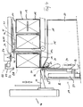
- Fig. 4
- eine Darstellung analog Fig. 3 bei veränderter Position von Organen,
- Fig. 5
- eine weitere Darstellung entsprechend Fig. 3 und Fig. 4 während einer Phase der Beseitigung einer durchtrennten Banderole,
- Fig. 6
- eine weitere veränderte Darstellung analog Fig. 3 bis Fig. 5 während des Abschubs eines Zuschnitt-Stapels auf einen Abförderer,
- Fig. 7
- ein Messer-Aggregat in perspektivischer, schematischer Darstellung,
- Fig. 8
- eine Einzelheit der Banderolen-Station im Grundriß.
Claims (10)
- Verfahren zum Transportieren von Zuschnitt-Stapeln (10) sowie zum Durchtrennen und Beseitigen einer den Zuschnitt-Stapel (10) umgebenden Banderole (11) im Bereich einer Banderolen-Station (19) durch ein Messer (23), wobei das Messer (23) im Bereich eines aufrechten Schenkels (12) der Banderole (11) zwischen Zuschnitten des Zuschnitt-Stapels (10) eingeführt und die Banderole (11) durch Relativbewegung von Messer (23) und Zuschnitt-Stapel (10) entlang dem aufrechten Schenkel (12) durchtrennt wird, dadurch gekennzeichnet, daß das Messer (23) im oberen Bereich des aufrechten Schenkels (12) zwischen oberen Zuschnitten des Zuschnitt-Stapels (10) eingeführt und die Banderole (11) in diesem Bereich durchtrennt wird, und daß der Schenkel (12) nach dem Trennen nach unten bis unter den Zuschnitt-Stapel (10) weggezogen wird.
- Verfahren nach Anspruch 1, dadurch gekennzeichnet, daß in einem zum Messer (23) gegenüberliegenden Bereich Druck auf die Oberseite des Zuschnitt-Stapels (10) und/oder auf den oberen Quersteg (14) der Banderole (11) ausgeübt wird, derart, daß der dem Messer (23) zugekehrte Bereich der oberen Zuschnitte und/oder des oberen Querstegs (14) geringfügig angehoben werden.
- Verfahren nach Anspruch 1 oder 2, dadurch gekennzeichnet, daß auf den oberen Quersteg (14) der Banderole bzw. auf den dem Messer (23) zugekehrten freien Bereich der Zuschnitte eine angebende Kraft ausgeübt wird, insbesondere durch Ansaugen des Querstegs (14) und/oder des oberen Zuschnitts.
- Verfahren nach Anspruch 1 oder einem der weiteren Ansprüche, dadurch gekennzeichnet, daß der banderolenfreie Zuschnitt-Stapel (10) durch einen Abförderer abtransportiert wird, wobei die Banderole (11) insgesamt nach unten weggezogen wird.
- Vorrichtung zur Durchführung des Verfahrens nach einem der Ansprüche 1 bis 4, mit einem in horizontaler Ebene sich erstreckenden, einseitig abstehenden und zwischen Zuschnitte des Zuschnitt-Stapels (10) eintretenden Messer (23), dadurch gekennzeichnet, daß das Messer (23) in einer Ebene zwischen oberen Zuschnitten, im Bereich des aufrechten Schenkels (12) relativ zum bewegungslosen Zuschnitt-Stapel (10) und zum Durchtrennen der Banderole (11) bewegbar ist, und daß ein Halteorgan (32) vorgesehen ist, welches den durchtrennten Schenkel (12) erfaßt und nach unten abzieht.
- Vorrichtung nach Anspruch 5, gekennzeichnet durch eine Anlagewand (31) zur Positionierung des Zuschnitt-Stapels (10) in der Banderolen-Station (19) auf einer Platte (21), wobei die Anlagewand (31) die Halteorgane zum Erfassen des Schenkels (12) der Banderole (11) aufweist, insbesondere Saugorgane (32), und zum Abziehen des Schenkels (12) bzw. der Banderole (11) in vertikaler Ebene auf- und abbewegbar ist.
- Vorrichtung nach Anspruch 5 oder einem der weiteren Ansprüche, dadurch gekennzeichnet, daß die Banderole (11) durch zusätzliche Zugorgane nach unten wegziehbar ist, insbesondere durch ein Zugwalzenpaar mit ortsfester Zugwalze (49) und an der Anlagewand (31) angeordneter Gegenwalze (50).
- Vorrichtung nach Anspruch 5 oder einem der weiteren Ansprüche, dadurch gekennzeichnet, daß die Banderole (11) bzw. ein oberer, horizontaler Quersteg (14) und/oder obere Zuschnitte des Zuschnitt-Stapels (10) zum Einführen des Messers (23) geringfügig anhebbar ist bzw. sind, insbesondere durch einen Sauger (30) und/oder durch ein auf die Banderole (11) bzw. auf den Zuschnitt-Stapel (10) wirkendes Druckorgan - eine Stempelplatte (29).
- Vorrichtung nach Anspruch 5 oder einem der weiteren Ansprüche, dadurch gekennzeichnet, daß der Zuschnitt-Stapel (10) nach Durchtrennen der Banderole (11) durch ein auf der zum durchtrennten Schenkel (12) gegenüberliegenden Seite am Zuschnitt-Stapel (10) angreifendes Schieberorgan bzw. eine Schiebereinheit (41) aus der Banderolen-Station (19) abschiebbar ist, vorzugsweise unmittelbar auf einen Mitnehmer bzw. eine Plattform (39) eines (Vertikalförderers 40) zum Abtransport der Zuschnitte.
- Vorrichtung nach Anspruch 9, dadurch gekennzeichnet, daß die Schiebereinheit (41) zum Abschieben des Zuschnitt-Stapels (10) aus vorzugsweise zwei aufrechten Mitnehmerstangen (42, 43) besteht, die durch Seitwärtsbewegung in die Bewegungsbahn der Zuschnitt-Stapel (10) und aus dieser herausbewegbar sowie zusätzlich in Förderrichtung der Zuschnitt-Stapel (10) bewegbar sind.
Applications Claiming Priority (2)
| Application Number | Priority Date | Filing Date | Title |
|---|---|---|---|
| DE4436330 | 1994-10-11 | ||
| DE19944436330 DE4436330A1 (de) | 1994-10-11 | 1994-10-11 | Verfahren und Vorrichtung zur Handhabung von Zuschnitt-Stapeln mit Banderolen |
Publications (2)
| Publication Number | Publication Date |
|---|---|
| EP0706946A1 EP0706946A1 (de) | 1996-04-17 |
| EP0706946B1 true EP0706946B1 (de) | 1998-07-29 |
Family
ID=6530499
Family Applications (1)
| Application Number | Title | Priority Date | Filing Date |
|---|---|---|---|
| EP19950115106 Expired - Lifetime EP0706946B1 (de) | 1994-10-11 | 1995-09-26 | Verfahren und Vorrichtung zum Handhaben von Zuschnitt-Stapeln mit Banderolen |
Country Status (4)
| Country | Link |
|---|---|
| US (1) | US5758362A (de) |
| EP (1) | EP0706946B1 (de) |
| JP (1) | JP3261024B2 (de) |
| DE (2) | DE4436330A1 (de) |
Cited By (1)
| Publication number | Priority date | Publication date | Assignee | Title |
|---|---|---|---|---|
| DE102008032368A1 (de) | 2008-07-10 | 2010-01-14 | Focke & Co.(Gmbh & Co. Kg) | Verfahren und Vorrichtung zum Durchtrennen einer einen Zuschnitt-Stapel umgebenden Banderole |
Families Citing this family (22)
| Publication number | Priority date | Publication date | Assignee | Title |
|---|---|---|---|---|
| DE19650689A1 (de) | 1996-12-06 | 1998-06-10 | Focke & Co | Vorrichtung zum Handhaben von Zuschnittstapeln |
| DE19728515A1 (de) * | 1997-07-04 | 1999-01-07 | Focke & Co | Verfahren und Vorrichtung zum Herstellen von Klappschachteln für Zigaretten |
| JPH11138665A (ja) * | 1997-11-12 | 1999-05-25 | Fuji Photo Film Co Ltd | ラベル剥離方法及び装置 |
| EP0933300B1 (de) * | 1998-01-30 | 2004-06-23 | Nippon Paper Industries Co., Ltd. | Verfahren und Vorrichtung zum Öffnen einer Verpackung unter Verwendung von miteinander verbundenen Teilen derselben |
| IT1304036B1 (it) * | 1998-07-15 | 2001-03-02 | Gd Spa | Metodo e dispositivo per l'alimentazione di sbozzati di materiale diincarto in una macchina impacchettatrice. |
| EP0980831B1 (de) * | 1998-08-20 | 2003-05-28 | Sinomec Ag | Verfahren und Vorrichtung zum Entfernen von Hüllen an Gegenständen |
| JP4059487B2 (ja) * | 2002-11-29 | 2008-03-12 | ジェイティエンジニアリング株式会社 | 部品供給装置 |
| CA2416241A1 (en) * | 2003-01-14 | 2004-07-14 | Labatt Brewing Company Limited | Bottom saw blade height adjustment |
| US7174695B2 (en) * | 2003-06-04 | 2007-02-13 | Porter Dan C | De-packaging machine |
| DE102004007488A1 (de) * | 2004-02-13 | 2005-09-15 | Heino Ilsemann Gmbh | Vorrichtung und Verfahren zum Entpacken von banderolierten Gegenständen |
| US7341416B1 (en) * | 2004-12-30 | 2008-03-11 | Rubtsov Yuriy N | Machine and method to feed filled bags, open the bags, empty the bags, and dispose of the empty bags |
| PL211905B1 (pl) * | 2006-03-17 | 2012-07-31 | Int Tobacco Machinery Poland | Sposób i urządzenie do usuwania z opakowań powłoki z tworzywa sztucznego |
| US7963086B2 (en) * | 2007-11-06 | 2011-06-21 | Porter Technologies, Llc | Package unbundling system |
| CA2905853A1 (en) * | 2013-03-12 | 2014-10-09 | Robotica, Inc. | Automated container cutting apparatus and method |
| CN105460307B (zh) * | 2015-12-21 | 2017-10-10 | 汕头市美宝制药有限公司 | 一种软膏无菌自动上管机 |
| PT3214004T (pt) * | 2016-03-03 | 2019-01-10 | Freixenet S A | Método de desembrulhar uma carga sobre a palete e dispositivo para levar a cabo o referido método |
| CN105711910B (zh) * | 2016-03-25 | 2018-05-18 | 云南昆船电子设备有限公司 | 基于机器人的烟包包装方形辅料自动上料气压系统 |
| JP6922451B2 (ja) * | 2017-06-08 | 2021-08-18 | コニカミノルタ株式会社 | 給紙装置 |
| CN111056099A (zh) * | 2019-12-24 | 2020-04-24 | 上海西派埃智能科技有限公司 | 面包袋自动拆封装置 |
| US11981023B2 (en) | 2020-01-17 | 2024-05-14 | Robotica, Inc. | Tote handling system with integrated hand and method of using same |
| US11981507B2 (en) | 2020-06-03 | 2024-05-14 | Robotica, Inc. | Tote handling system with tote handler and method of using same |
| WO2023281036A1 (fr) | 2021-07-08 | 2023-01-12 | Sidel Participations | Lot compact de recipients groupés, procédé de conditionnement et installation |
Family Cites Families (19)
| Publication number | Priority date | Publication date | Assignee | Title |
|---|---|---|---|---|
| CH625756A5 (de) * | 1978-03-02 | 1981-10-15 | Born Ag Peter | |
| US4390313A (en) * | 1980-03-27 | 1983-06-28 | Hoehn John Walter | Method and apparatus for depacking articles |
| DE3229765A1 (de) | 1982-08-10 | 1984-02-16 | GAO Gesellschaft für Automation und Organisation mbH, 8000 München | Vorrichtung zum entfernen einer banderole von einem blattbuendel |
| GB8333856D0 (en) | 1983-12-20 | 1984-02-01 | Delco Prod Overseas | Sheet sorting apparatus |
| DE3443362A1 (de) * | 1984-11-28 | 1986-05-28 | Kodak Ag, 7000 Stuttgart | Kopiergeraet |
| NL8500606A (nl) * | 1985-03-04 | 1986-10-01 | Endra Bv | Werkwijze en inrichting voor het doorsnijden en het verwijderen van een om een voorwerp of een stapel voorwerpen aangebracht draad- of bandvormig omsnoeringselement. |
| NL8601747A (nl) * | 1986-07-04 | 1988-02-01 | Speciaalmachinefabriek J H Van | Inrichting voor het van een beladen pallet verwijderen van de omsnoeringsbanden. |
| FR2633587B1 (fr) * | 1988-06-29 | 1991-03-29 | Vega Automation | Procede et dispositif pour rompre et enlever un lien entourant un paquet. procede et appareil d'alimentation en decoupes utilisant ce procede et ce dispositif |
| JP2746994B2 (ja) * | 1989-03-30 | 1998-05-06 | 株式会社東芝 | 紙葉類把の帯除去装置 |
| US5190430A (en) * | 1989-08-01 | 1993-03-02 | G. D. S.P.A. | Apparatus for feeding packaging machines with stacks of sheet material |
| IT1244236B (it) * | 1990-09-11 | 1994-07-08 | Gd Spa | Dispositivo per l'alimentazione automatica di pile di sbozzati ad una macchina utilizzatrice ad esmpio una macchina incartatrice. |
| US5101793A (en) * | 1990-10-30 | 1992-04-07 | Sample Larry A | Manually adjustable override for fuel injection regulators |
| DE4105149A1 (de) * | 1991-02-20 | 1992-08-27 | Truetzschler & Co | Verfahren und vorrichtung zum entfernen der verpackung (emballage), z. b. saecke o. dgl. von textilen rohstoffballen, insbesondere baumwoll- und chemiefaserballen |
| JPH05269693A (ja) * | 1992-03-23 | 1993-10-19 | Ishii Kogyo Kk | バンド切断装置 |
| US5282346A (en) * | 1992-05-14 | 1994-02-01 | Oji Seitai Kaisha, Ltd. | Unwrapping apparatus with swing arms and grippers |
| IT1258130B (it) * | 1992-12-24 | 1996-02-20 | Comas Spa | Macchina automatica per il taglio e la rimozione dell'involucro di unaballa, in particolare di una balla di tabacco. |
| DE4301169A1 (de) * | 1993-01-20 | 1994-07-21 | Focke & Co | Verfahren und Vorrichtung zur Handhabung von Zuschnitt-Stapeln mit Banderole |
| US5419095A (en) * | 1993-03-09 | 1995-05-30 | Dyco | Bag stripping apparatus |
| EP0639663B1 (de) * | 1993-08-12 | 1998-09-30 | Maschinenfabrik Rieter Ag | Verfahren und Vorrichtung zur Behandlung von Fremdkörpern bei der Ballenabtragung |
-
1994
- 1994-10-11 DE DE19944436330 patent/DE4436330A1/de not_active Withdrawn
-
1995
- 1995-09-26 EP EP19950115106 patent/EP0706946B1/de not_active Expired - Lifetime
- 1995-09-26 DE DE59502963T patent/DE59502963D1/de not_active Expired - Lifetime
- 1995-10-10 US US08/540,486 patent/US5758362A/en not_active Expired - Fee Related
- 1995-10-11 JP JP26333995A patent/JP3261024B2/ja not_active Expired - Fee Related
Cited By (2)
| Publication number | Priority date | Publication date | Assignee | Title |
|---|---|---|---|---|
| DE102008032368A1 (de) | 2008-07-10 | 2010-01-14 | Focke & Co.(Gmbh & Co. Kg) | Verfahren und Vorrichtung zum Durchtrennen einer einen Zuschnitt-Stapel umgebenden Banderole |
| WO2010003483A1 (de) | 2008-07-10 | 2010-01-14 | Focke & Co. (Gmbh & Co. Kg) | Verfahren und vorrichtung zum durchtrennen einer einen zuschnitt-stapel umgebenden banderole |
Also Published As
| Publication number | Publication date |
|---|---|
| JP3261024B2 (ja) | 2002-02-25 |
| EP0706946A1 (de) | 1996-04-17 |
| JPH08175527A (ja) | 1996-07-09 |
| DE4436330A1 (de) | 1996-04-18 |
| US5758362A (en) | 1998-06-02 |
| DE59502963D1 (de) | 1998-09-03 |
Similar Documents
| Publication | Publication Date | Title |
|---|---|---|
| EP0706946B1 (de) | Verfahren und Vorrichtung zum Handhaben von Zuschnitt-Stapeln mit Banderolen | |
| EP0421148B1 (de) | Verfahren und Vorrichtung zum Transport von Stapeln von Zuschnitten für die Herstellung von (Zigaretten-)Packungen | |
| EP2296983B1 (de) | Verfahren und vorrichtung zum durchtrennen einer einen zuschnitt-stapel umgebenden banderole | |
| EP0560112B1 (de) | Vorrichtung zum Zuführen von Zwischenlagen zu einem Stapel | |
| EP2197745B1 (de) | Verfahren zum handhaben von stückigen oder körnigen tabakartikeln, insbesondere kautabak oder kautabakersatz (snus) | |
| EP0444547B1 (de) | Verfahren und Vorrichtung zum Fördern von Banderolen zwecks Übergabe an Packungen | |
| EP0258597A2 (de) | Vorrichting zum Zuführen von Zuschnitten zu einer Verpackungsmaschine | |
| EP0031515A1 (de) | Vorrichtung zum Herstellen von Packungs-Zuschnitten durch Abtrennen von einer fortlaufenden Bahn | |
| EP0149076B1 (de) | Verfahren und Vorrichtung zum Anbringen von Trinkhalmen an Getränkebehältern, insbesondere an Getränkebeuteln | |
| WO2022096456A1 (de) | Packungsgebinde für produkte der zigarettenindustrie und verfahren zur herstellung derselben | |
| DE69104553T2 (de) | Vorrichtung zum Herstellen von Kartons aus flachen hülsenartigen Zuschnitten. | |
| EP0607626B1 (de) | Verfahren und Vorrichtung zur Handhabung von Zuschnitt-Stapeln mit Banderole | |
| EP0612661A1 (de) | Vorrichtung zum Erstellen einer Transportverpackung | |
| EP0716637B1 (de) | Verfahren und vorrichtung zum formen und etikettieren von verpackungsbehältern | |
| DE102008029766B4 (de) | Vorrichtung zum Verpacken von flachen Artikeln | |
| EP0663356A1 (de) | Vorrichtung zur Vereinzeln von Packungen | |
| DE3804946A1 (de) | Verfahren und vorrichtung zum vereinzeln von ebenen teilen | |
| EP4367049A1 (de) | Verfahren und vorrichtung zur handhabung von zuschnitten aus verpackungsmaterial | |
| DE4220026A1 (de) | Verfahren und Vorrichtung zum Abräumen von Zuschnittstapeln von einer Palette oder dergleichen | |
| EP2655197A1 (de) | Verfahren zum entfolieren von verpackungseinheiten und entfolierstation | |
| DE4416540C1 (de) | Verfahren und Vorrichtung zum Umwickeln von Quadern, insbesondere Isolierstoffballen, mit Einwickelmaterial | |
| EP0562432B1 (de) | Verfahren und Vorrichtung zum Abräumen von Zuschnittstapeln von einer Palette oder dergleichen | |
| EP0888969A1 (de) | Verfahren und Vorrichtung zum Herstellen von Klappschachteln für Zigaretten | |
| DE3603484A1 (de) | Verfahren und vorrichtung zum geordneten abtransport von papierstapeln | |
| DE102022113839A1 (de) | Verfahren und Vorrichtung zum Anbringen von Aufreißstreifen an einer fortlaufenden Materialbahn |
Legal Events
| Date | Code | Title | Description |
|---|---|---|---|
| PUAI | Public reference made under article 153(3) epc to a published international application that has entered the european phase |
Free format text: ORIGINAL CODE: 0009012 |
|
| AK | Designated contracting states |
Kind code of ref document: A1 Designated state(s): DE GB IT |
|
| 17P | Request for examination filed |
Effective date: 19960601 |
|
| 17Q | First examination report despatched |
Effective date: 19970327 |
|
| GRAG | Despatch of communication of intention to grant |
Free format text: ORIGINAL CODE: EPIDOS AGRA |
|
| GRAG | Despatch of communication of intention to grant |
Free format text: ORIGINAL CODE: EPIDOS AGRA |
|
| GRAH | Despatch of communication of intention to grant a patent |
Free format text: ORIGINAL CODE: EPIDOS IGRA |
|
| GRAH | Despatch of communication of intention to grant a patent |
Free format text: ORIGINAL CODE: EPIDOS IGRA |
|
| GRAA | (expected) grant |
Free format text: ORIGINAL CODE: 0009210 |
|
| AK | Designated contracting states |
Kind code of ref document: B1 Designated state(s): DE GB IT |
|
| GBT | Gb: translation of ep patent filed (gb section 77(6)(a)/1977) |
Effective date: 19980729 |
|
| REF | Corresponds to: |
Ref document number: 59502963 Country of ref document: DE Date of ref document: 19980903 |
|
| PLBE | No opposition filed within time limit |
Free format text: ORIGINAL CODE: 0009261 |
|
| STAA | Information on the status of an ep patent application or granted ep patent |
Free format text: STATUS: NO OPPOSITION FILED WITHIN TIME LIMIT |
|
| 26N | No opposition filed | ||
| REG | Reference to a national code |
Ref country code: GB Ref legal event code: IF02 |
|
| PGFP | Annual fee paid to national office [announced via postgrant information from national office to epo] |
Ref country code: GB Payment date: 20070926 Year of fee payment: 13 |
|
| PGFP | Annual fee paid to national office [announced via postgrant information from national office to epo] |
Ref country code: IT Payment date: 20070926 Year of fee payment: 13 |
|
| GBPC | Gb: european patent ceased through non-payment of renewal fee |
Effective date: 20080926 |
|
| PG25 | Lapsed in a contracting state [announced via postgrant information from national office to epo] |
Ref country code: IT Free format text: LAPSE BECAUSE OF NON-PAYMENT OF DUE FEES Effective date: 20080926 |
|
| PG25 | Lapsed in a contracting state [announced via postgrant information from national office to epo] |
Ref country code: GB Free format text: LAPSE BECAUSE OF NON-PAYMENT OF DUE FEES Effective date: 20080926 |
|
| PGFP | Annual fee paid to national office [announced via postgrant information from national office to epo] |
Ref country code: DE Payment date: 20090924 Year of fee payment: 15 |
|
| REG | Reference to a national code |
Ref country code: DE Ref legal event code: R119 Ref document number: 59502963 Country of ref document: DE Effective date: 20110401 |
|
| PG25 | Lapsed in a contracting state [announced via postgrant information from national office to epo] |
Ref country code: DE Free format text: LAPSE BECAUSE OF NON-PAYMENT OF DUE FEES Effective date: 20110401 |