EP0709019A1 - Kreiselschwader - Google Patents
Kreiselschwader Download PDFInfo
- Publication number
- EP0709019A1 EP0709019A1 EP95113738A EP95113738A EP0709019A1 EP 0709019 A1 EP0709019 A1 EP 0709019A1 EP 95113738 A EP95113738 A EP 95113738A EP 95113738 A EP95113738 A EP 95113738A EP 0709019 A1 EP0709019 A1 EP 0709019A1
- Authority
- EP
- European Patent Office
- Prior art keywords
- swath
- former
- rotor
- lifting cylinder
- lifting
- Prior art date
- Legal status (The legal status is an assumption and is not a legal conclusion. Google has not performed a legal analysis and makes no representation as to the accuracy of the status listed.)
- Granted
Links
- 230000005484 gravity Effects 0.000 description 3
- 230000002349 favourable effect Effects 0.000 description 1
- 230000001681 protective effect Effects 0.000 description 1
Images



Classifications
-
- A—HUMAN NECESSITIES
- A01—AGRICULTURE; FORESTRY; ANIMAL HUSBANDRY; HUNTING; TRAPPING; FISHING
- A01D—HARVESTING; MOWING
- A01D78/00—Haymakers with tines moving with respect to the machine
- A01D78/08—Haymakers with tines moving with respect to the machine with tine-carrying rotary heads or wheels
- A01D78/10—Haymakers with tines moving with respect to the machine with tine-carrying rotary heads or wheels the tines rotating about a substantially vertical axis
- A01D78/1007—Arrangements to facilitate transportation specially adapted therefor
- A01D78/1014—Folding frames
Definitions
- the innovation relates to rotary swathers according to the preamble of the main claim.
- Rotary swathers are known in which swath rotors can be folded up hydraulically to achieve a favorable transport position, e.g. B. according to the prospectus of CLAAS-Vertriebsgesellschaft mbH, 33416 Harsewinkel, regarding swathers "LINER 390 S / 430 S / 770/1550". According to this publication, however, the associated swath former must be folded up into the transport position by hand. It is still z. B. from the publication EP-PS 0 526 365 known to fold up the swath former hydraulically for transport. The combination of both hydraulically controlled actuations has not yet been carried out because many older tractors only have a controllable pressure connection for the attachments.
- the swivel axes for the swath rotor and for the swath former can be arranged in such a way that they enclose an angle of significantly less than 90 ° .
- the center of gravity of the swath former then lies in the swiveled-up transport position lower than the swivel joint, which creates a moment that holds the swath former in this position.
- Two swath rotors (2, 3) are articulated in a height-adjustable manner on the two-wheeled chassis (1) of a rotary swather.
- the support arms (4, 5) are connected to brackets (8) of the chassis (1) via horizontal hinge pins (6, 7). In the working position, they are in an approximately horizontal plane. To achieve a transport position, they can be pivoted into an approximately vertical position using hydraulic lifting cylinders (9) (FIG. 2, dashed lines).
- the support arms (4, 5) are firmly connected at one end to cross members (10, 11), which essentially serve to mount protective bars (12).
- a support (13) is attached to one of the cross members (11) and a cantilever arm (15) is articulated on it by means of a fork joint (14).
- a swath former (16) At its free end there is a swath former (16), which is arranged in the working position in a vertical plane lying approximately in the direction of travel at a distance from the working top (3).
- the boom arm (15) and thus also the swath former (16) can be moved into an approximately vertical position by means of a hydraulic lifting cylinder (17) (FIG. 3) in order to achieve a transport position (FIG. 2, dashed, FIG. 3, dashed).
- the extension of the axis of rotation of the fork joint (14) and the extension of the axis of the joint pin (7) enclose an angle ⁇ of approximately 70 ° (FIG. 1).
- the hydraulic lifting cylinders (9) and (17) are connected to a common pressure line controlled by the tractor, which is not illustrated here.
- the effective cross sections of the lifting cylinders (9) and (17) are designed so that when the pressure in the pressure line rises, the lifting cylinder (17) is first extended to actuate the extension arm (15
- the boom arm (15) and the swath former (16) then assume the position shown in broken lines in FIG. If the pressure in the pressure line increases further, the lifting cylinders (9) are also extended, which cause the swath rotors (2, 3) to be moved into an approximately vertical transport position. The boom arm (15) and the swath former (16) then have the position shown in broken lines in FIG.
Landscapes
- Life Sciences & Earth Sciences (AREA)
- Environmental Sciences (AREA)
- Soil Working Implements (AREA)
- Paper (AREA)
- Centrifugal Separators (AREA)
- Cold Cathode And The Manufacture (AREA)
- Treatment Of Fiber Materials (AREA)
- Separation, Recovery Or Treatment Of Waste Materials Containing Plastics (AREA)
Abstract
Description
- Die Neuerung bezieht sich auf Kreiselschwader nach dem Oberbegriff des Hauptanspruches.
- Es sind Kreiselschwader bekannt, bei denen Schwadkreisel zur Erreichung einer günstigen Transportstellung hydraulisch hochklappbar sind, z. B. nach dem Prospekt der CLAAS-Vertriebsgesellschaft mbH, 33416 Harsewinkel, betreffend Schwader "LINER 390 S/ 430 S/ 770/ 1550". Nach dieser Druckschrift muß der Zugehörige Schwadformer jedoch von Hand in die Transportstellung hochgeklappt werden. Es ist weiterhin z. B. aus der Druckschrift EP-PS 0 526 365 bekannt, den Schwadformer zum Transport hydraulisch hochzuklappen. Die Kombination beider hydraulisch gesteuerter Betätigungen wurde bislang nicht betrieben, weil bei vielen älteren Schleppern nur ein steuerbarer Druckanschluß für die Anbaugeräte zur Verfügung steht.
- Dieser Nachteil wird nach der Neuerung dadurch ausgeschaltet, daß sowohl die Hubzylinder für die Schwadkreisel, als auch der Hubzylinder für den Schwadformer von einer gemeinsamen, vom Schlepper aus beaufschlagten Druckleitung angesteuert werden.
- Durch die Wahl geeigneter Wirkquerschnitte für die Hubzylinder kann weiterhin erreicht werden, daß bei Druckanstieg in der Druckleitung zuerst der Hubzylinder für den Schwadformer, und erst nach Erreichung dessen Endstellung und bei weiterem Druckanstieg, der Hubzylinder für den Schwadkreisel betätigt wird.
- Damit bei einem eventuellen Druckabfall in der Transportstellung der hochgeklappte Schwadformer in einer durch Schwerkraft gesicherten Position verbleibt, können nach einem weiteren Merkmal der Neuerung die Schwenkachsen für den Schwadkreisel und für den Schwadformer so angeordnet werden, daß sie einen Winkel von deutlich weniger als 90° einschließen. Der Schwerpunkt des Schwadformers liegt dann in der hochgeschwenkten Transportstellung tiefer als das Schwenkgelenk, wodurch ein Moment entsteht, das den Schwadformer in dieser Lage festhält.
- Die Neuerung wird anhand von vier Abbildungen beispielsweise erläutert.
- Figur 1
- zeigt einen Kreiselschwader mit zwei Schwadkreiseln in Draufsicht,
- Figur 2
- zeigt den gleichen Gegenstand in einer Teilansicht in Richtung des Pfeiles A der Figur 1,
- Figur 3
- zeigt eine vergrößerte Teilansicht des Schwadformers in Richtung des Pfeiles C der Figur 1,
- Figur 4
- zeigt eine Teilansicht in Richtung des Pfeiles B der Figur 1 mit einem Schwadkreisel in Transportstellung.
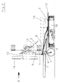
- An dem zweirädrigen Fahrgestell (1) eines Kreiselschwaders sind zwei Schwadkreisel (2, 3) höhenbeweglich angelenkt. Deren Tragarme (4, 5) sind über horizontale Gelenkbolzen (6, 7) mit Konsolen (8) des Fahrgestelles (1) verbunden. In der Arbeitsstellung liegen sie in einer etwa horizontalen Ebene. Zur Erzielung einer Transportstellung können sie mit hydraulischen Hubzylindern (9) in eine etwa vertikale Lage verschwenkt werden (Figur 2, gestrichelt). Die Tragarme (4, 5) sind an einem Ende mit Querträgern (10, 11) fest verbunden, die im wesentlichen der Lagerung von Schutzbügeln (12) dienen. An einem der Querträger (11) ist eine Stütze (13) befestigt, an der mittels eines Gabelgelenkes (14) ein Auslegerarm (15) angelenkt ist. An dessen freiem Ende befindet sich ein Schwadformer (16), der in der Arbeitsstellung in einer etwa in Fahrtrichtung liegenden Vertikalebene im Abstand zu dem Arbeitskreisel (3) angeordnet ist. Der Auslegerarm (15) und damit auch der Schwadformer (16) können mittels eines hydraulischen Hubzylinders (17) (Figur 3) zur Erzielung einer Transportstellung in eine etwa senkrechte Stellung verbracht werden (Figur 2, gestrichelt, Figur 3, gestrichelt). Die Verlängerung der Drehachse des Gabelgelenkes (14) und die Verlängerung der Achse des Gelenkbolzens (7) schließen einen Winkel α von etwa 70° ein (Figur 1). Die hydraulischen Hubzylinder (9) und (17) sind an eine gemeinsame, vom Schlepper aus angesteuerte Druckleitung angeschlossen, die hier nicht bildlich dargestellt ist. Die Wirkquerschnitte der Hubzylinder (9) und (17) sind so ausgelegt, daß bei Druckanstieg in der Druckleitung zuerst der Hubzylinder (17) für die Betätigung des Auslegerarmes (15) ausgefahren wird, bis dieser seine Endstellung erreicht.
- Der Auslegerarm (15) und der Schwadformer (16) nehmen dann die in Figur 2 gestrichelt gezeichnete Stellung ein. Bei weiterem Druckanstieg in der Druckleitung werden auch die Hubzylinder (9) ausgefahren, die bewirken, daß die Schwadkreisel (2, 3) in eine etwa senkrechte Transportstellung verbracht werden. Der Auslegerarm (15) und der Schwadformer (16) haben dann die in Figur 2 strichpunktiert gezeichnete Stellung.
- Die Umstellung des Kreiselschwaders von der Arbeitsstellung (Figur 1) in die Transportstellung (Figur 2 und Figur 4) geschieht also in der Reihenfolge: Hochschwenken des Auslegerarmes (15) und des Schwadformers (16), danach Hochschwenken der Schwadkreisel (2, 3).
- Dadurch, daß der Winkel α von deutlich weniger als 90° zwischen der Schwenkachse (7) des Schwadkreisels (3) und der Schwenkachse (14) des Schwadformers (16) ausgebildet ist, liegt der Schwerpunkt des Schwadformers (16) in der Transportstellung (Figur 4) deutlich tiefer als dessen Gabelgelenk (14), wodurch gesichert ist, daß der Schwadformer (16) in der Transportstellung auch bei Druckabfall in der Druckleitung eine stabile Stellung einnimmt.
Claims (3)
- Kreiselschwader mit mindestens einem, zur Erzielung einer Transportstellung mittels eines hydraulischen Hubzylinders hochschwenkbaren Schwadkreisel bzw. einem, für die Transportstellung hydraulisch hochklappbaren Schwadformer, dadurch gekennzeichnet, daß die Hubzylinder (9) für die Schwadkreisel (2, 3) und der Hubzylinder (17) für den Schwadformer (16) von einer gemeinsamen, vom Schlepper aus beaufschlagten Druckleitung angesteuert werden.
- Kreiselschwader nach Anspruch 1, dadurch gekennzeichnet, daß die Querschnitte der Hubzylinder (9, 17) so ausgelegt sind, daß bei Druckanstieg in der Druckleitung zuerst der Hubzylinder (17) für den Schwadformer (16) bis zu seinem Endanschlag ausgefahren wird und erst bei weiterem Druckanstieg in der Druckleitung die Hubzylinder (9) für die Aushebung der Schwadkreisel (2, 3) betätigt werden.
- Kreiselschwader nach den Ansprüchen 1 und 2, dadurch gekennzeichnet, daß die Schwenkachse (7) für den Schwadkreisel (3) und die Schwenkachse (14) für den Schwadformer (16) einen Winkel α von deutlich weniger als 90° einschließen.
Applications Claiming Priority (2)
| Application Number | Priority Date | Filing Date | Title |
|---|---|---|---|
| DE9417375U | 1994-10-29 | ||
| DE9417375U DE9417375U1 (de) | 1994-10-29 | 1994-10-29 | Kreiselschwader |
Publications (2)
| Publication Number | Publication Date |
|---|---|
| EP0709019A1 true EP0709019A1 (de) | 1996-05-01 |
| EP0709019B1 EP0709019B1 (de) | 1998-06-10 |
Family
ID=6915461
Family Applications (1)
| Application Number | Title | Priority Date | Filing Date |
|---|---|---|---|
| EP95113738A Expired - Lifetime EP0709019B1 (de) | 1994-10-29 | 1995-09-01 | Kreiselschwader |
Country Status (3)
| Country | Link |
|---|---|
| EP (1) | EP0709019B1 (de) |
| AT (1) | ATE167022T1 (de) |
| DE (2) | DE9417375U1 (de) |
Cited By (3)
| Publication number | Priority date | Publication date | Assignee | Title |
|---|---|---|---|---|
| US6164051A (en) * | 1996-08-06 | 2000-12-26 | Maasland N.V. | Machine combination, a rake and pick-up and displacing member, as well as a method |
| NL1031730C2 (nl) | 2006-05-02 | 2007-11-05 | Maasland Nv | Hooibouwmachine. |
| EP1852010A2 (de) | 2006-05-02 | 2007-11-07 | Maasland N.V. | Heuerntemaschine |
Families Citing this family (2)
| Publication number | Priority date | Publication date | Assignee | Title |
|---|---|---|---|---|
| DE19920755A1 (de) * | 1999-05-05 | 2000-11-09 | Claas Saulgau Gmbh | Heuwerbungsmaschine |
| CN116081535B (zh) * | 2023-02-24 | 2025-05-16 | 中国矿业大学 | 一种用于高层建筑的避难层间疏散救援平台及方法 |
Citations (5)
| Publication number | Priority date | Publication date | Assignee | Title |
|---|---|---|---|---|
| DE8807054U1 (de) * | 1988-05-30 | 1989-06-22 | Alois Pöttinger Landmaschinen-Gesellschaft mbH, 8900 Augsburg | Heuwerbungsmaschine |
| DE9015320U1 (de) * | 1990-11-08 | 1991-01-17 | H. Niemeyer Söhne GmbH & Co KG, 4446 Hörstel | Heuwerbungsmaschine |
| EP0507408A1 (de) * | 1991-04-03 | 1992-10-07 | C. van der Lely N.V. | Landwirtschaftliche Maschine |
| EP0526365A1 (de) | 1991-07-11 | 1993-02-03 | Kuhn S.A. | Heuwerbungsmaschine, insbesondere Schwader für geschnittenes Pflanzengut |
| DE9216498U1 (de) * | 1992-12-03 | 1993-02-11 | H. Niemeyer Söhne GmbH & Co KG, 4446 Hörstel | Heuwerbungsmaschine |
Family Cites Families (4)
| Publication number | Priority date | Publication date | Assignee | Title |
|---|---|---|---|---|
| US3799272A (en) * | 1972-05-16 | 1974-03-26 | D Watson | Six and eight row cultivator and planter frame |
| DE3532114A1 (de) * | 1985-09-09 | 1987-03-19 | Hans Peter Hartmann | Frontmaehwerk fuer schlepper |
| DE4110265A1 (de) * | 1991-03-28 | 1992-10-01 | Krone Bernhard Gmbh Maschf | Heuwerbungsmaschine |
| DE9114316U1 (de) * | 1991-11-18 | 1992-02-06 | H. Niemeyer Söhne GmbH & Co KG, 4446 Hörstel | Heuwerbungsmaschine |
-
1994
- 1994-10-29 DE DE9417375U patent/DE9417375U1/de not_active Expired - Lifetime
-
1995
- 1995-09-01 EP EP95113738A patent/EP0709019B1/de not_active Expired - Lifetime
- 1995-09-01 AT AT95113738T patent/ATE167022T1/de not_active IP Right Cessation
- 1995-09-01 DE DE59502486T patent/DE59502486D1/de not_active Expired - Lifetime
Patent Citations (5)
| Publication number | Priority date | Publication date | Assignee | Title |
|---|---|---|---|---|
| DE8807054U1 (de) * | 1988-05-30 | 1989-06-22 | Alois Pöttinger Landmaschinen-Gesellschaft mbH, 8900 Augsburg | Heuwerbungsmaschine |
| DE9015320U1 (de) * | 1990-11-08 | 1991-01-17 | H. Niemeyer Söhne GmbH & Co KG, 4446 Hörstel | Heuwerbungsmaschine |
| EP0507408A1 (de) * | 1991-04-03 | 1992-10-07 | C. van der Lely N.V. | Landwirtschaftliche Maschine |
| EP0526365A1 (de) | 1991-07-11 | 1993-02-03 | Kuhn S.A. | Heuwerbungsmaschine, insbesondere Schwader für geschnittenes Pflanzengut |
| DE9216498U1 (de) * | 1992-12-03 | 1993-02-11 | H. Niemeyer Söhne GmbH & Co KG, 4446 Hörstel | Heuwerbungsmaschine |
Cited By (6)
| Publication number | Priority date | Publication date | Assignee | Title |
|---|---|---|---|---|
| US6164051A (en) * | 1996-08-06 | 2000-12-26 | Maasland N.V. | Machine combination, a rake and pick-up and displacing member, as well as a method |
| NL1031730C2 (nl) | 2006-05-02 | 2007-11-05 | Maasland Nv | Hooibouwmachine. |
| EP1852010A2 (de) | 2006-05-02 | 2007-11-07 | Maasland N.V. | Heuerntemaschine |
| EP2113163A2 (de) | 2006-05-02 | 2009-11-04 | Maasland N.V. | Heuerntemaschine |
| EP2263441A2 (de) | 2006-05-02 | 2010-12-22 | Maasland N.V. | Heuwerbungsmachine |
| EP2263441A3 (de) * | 2006-05-02 | 2012-07-25 | Maasland N.V. | Heuwerbungsmachine |
Also Published As
| Publication number | Publication date |
|---|---|
| DE59502486D1 (de) | 1998-07-16 |
| DE9417375U1 (de) | 1995-01-19 |
| EP0709019B1 (de) | 1998-06-10 |
| ATE167022T1 (de) | 1998-06-15 |
Similar Documents
| Publication | Publication Date | Title |
|---|---|---|
| EP0044569B1 (de) | Zusammen- und auffaltbares Gerät oder Werkzeugträger, insb. für landwirtschaftliche Maschinen | |
| DE69004287T2 (de) | Hydraulische Rohranordnung für einen Heckbagger. | |
| DE3024664A1 (de) | Landwirtschaftliches mehrzweckfahrzeug | |
| EP0147832A2 (de) | Landwirtschaftlich nutzbares Arbeitsgerät | |
| EP0391093B1 (de) | Landwirtschaftliche Arbeitsmaschine | |
| EP0381970B1 (de) | Kreiselheumaschinen | |
| EP1163830A1 (de) | Gezogenes landwirtschaftliches Gerät | |
| EP0709019B1 (de) | Kreiselschwader | |
| DE3632767A1 (de) | Kreiselheuwerbungsmaschine | |
| EP0571794A1 (de) | Landwirtschaftliche Arbeitsmaschine, besonders Kreiselheuwender | |
| EP2591662B1 (de) | Heuwerbungsmaschine | |
| DE3709097C2 (de) | ||
| DE2613027B2 (de) | Heuwerbungsmaschine | |
| DE3644019C2 (de) | ||
| DE3801895A1 (de) | Vorrichtung an der frontseite eines ackerschleppers zum anheben eines zusatzgewichttraegers in eine transportstellung | |
| DE3224269A1 (de) | Auswurfkruemmer fuer landwirtschaftliche maschinen | |
| DE3739114C2 (de) | Schutzvorrichtung für Kreiselheumaschinen | |
| DE3448426C2 (de) | Landwirtschaftliche Maschine | |
| EP1597953B1 (de) | Landwirtschaftliche Maschine | |
| DE3409515C2 (de) | ||
| DE2946521A1 (de) | Traktor mit hydraulisch betaetigbarem anbaugeraet | |
| DE4131012A1 (de) | Rueckezug | |
| EP0316559A2 (de) | Schutzvorrichtung für Kreiselheumaschinen | |
| DE69530808T2 (de) | Gezogenes landwirtschaftliches Gerät | |
| AT408176B (de) | Fahrzeug zum ernten von bäumen und zum transportieren von baumstämmen |
Legal Events
| Date | Code | Title | Description |
|---|---|---|---|
| PUAI | Public reference made under article 153(3) epc to a published international application that has entered the european phase |
Free format text: ORIGINAL CODE: 0009012 |
|
| AK | Designated contracting states |
Kind code of ref document: A1 Designated state(s): AT CH DE FR LI NL |
|
| 17P | Request for examination filed |
Effective date: 19961009 |
|
| 17Q | First examination report despatched |
Effective date: 19961119 |
|
| GRAG | Despatch of communication of intention to grant |
Free format text: ORIGINAL CODE: EPIDOS AGRA |
|
| GRAG | Despatch of communication of intention to grant |
Free format text: ORIGINAL CODE: EPIDOS AGRA |
|
| GRAH | Despatch of communication of intention to grant a patent |
Free format text: ORIGINAL CODE: EPIDOS IGRA |
|
| GRAH | Despatch of communication of intention to grant a patent |
Free format text: ORIGINAL CODE: EPIDOS IGRA |
|
| GRAA | (expected) grant |
Free format text: ORIGINAL CODE: 0009210 |
|
| AK | Designated contracting states |
Kind code of ref document: B1 Designated state(s): AT CH DE FR LI NL |
|
| REF | Corresponds to: |
Ref document number: 167022 Country of ref document: AT Date of ref document: 19980615 Kind code of ref document: T |
|
| REG | Reference to a national code |
Ref country code: CH Ref legal event code: NV Representative=s name: TROESCH SCHEIDEGGER WERNER AG Ref country code: CH Ref legal event code: EP |
|
| REF | Corresponds to: |
Ref document number: 59502486 Country of ref document: DE Date of ref document: 19980716 |
|
| ET | Fr: translation filed | ||
| PLBE | No opposition filed within time limit |
Free format text: ORIGINAL CODE: 0009261 |
|
| STAA | Information on the status of an ep patent application or granted ep patent |
Free format text: STATUS: NO OPPOSITION FILED WITHIN TIME LIMIT |
|
| 26N | No opposition filed | ||
| PGFP | Annual fee paid to national office [announced via postgrant information from national office to epo] |
Ref country code: CH Payment date: 20020924 Year of fee payment: 8 |
|
| PGFP | Annual fee paid to national office [announced via postgrant information from national office to epo] |
Ref country code: DE Payment date: 20021009 Year of fee payment: 9 |
|
| PGFP | Annual fee paid to national office [announced via postgrant information from national office to epo] |
Ref country code: FR Payment date: 20030819 Year of fee payment: 9 |
|
| PGFP | Annual fee paid to national office [announced via postgrant information from national office to epo] |
Ref country code: AT Payment date: 20030825 Year of fee payment: 9 |
|
| PGFP | Annual fee paid to national office [announced via postgrant information from national office to epo] |
Ref country code: NL Payment date: 20030828 Year of fee payment: 9 |
|
| PG25 | Lapsed in a contracting state [announced via postgrant information from national office to epo] |
Ref country code: LI Free format text: LAPSE BECAUSE OF NON-PAYMENT OF DUE FEES Effective date: 20030930 Ref country code: CH Free format text: LAPSE BECAUSE OF NON-PAYMENT OF DUE FEES Effective date: 20030930 |
|
| REG | Reference to a national code |
Ref country code: CH Ref legal event code: PL |
|
| PG25 | Lapsed in a contracting state [announced via postgrant information from national office to epo] |
Ref country code: DE Free format text: LAPSE BECAUSE OF THE APPLICANT RENOUNCES Effective date: 20040826 |
|
| PG25 | Lapsed in a contracting state [announced via postgrant information from national office to epo] |
Ref country code: AT Free format text: LAPSE BECAUSE OF NON-PAYMENT OF DUE FEES Effective date: 20040901 |
|
| PG25 | Lapsed in a contracting state [announced via postgrant information from national office to epo] |
Ref country code: NL Free format text: LAPSE BECAUSE OF NON-PAYMENT OF DUE FEES Effective date: 20050401 |
|
| PG25 | Lapsed in a contracting state [announced via postgrant information from national office to epo] |
Ref country code: FR Free format text: LAPSE BECAUSE OF NON-PAYMENT OF DUE FEES Effective date: 20050531 |
|
| NLV4 | Nl: lapsed or anulled due to non-payment of the annual fee |
Effective date: 20050401 |
|
| REG | Reference to a national code |
Ref country code: FR Ref legal event code: ST |