EP0712289B1 - Tv camera with rotational orientation correction - Google Patents
Tv camera with rotational orientation correction Download PDFInfo
- Publication number
- EP0712289B1 EP0712289B1 EP94918697A EP94918697A EP0712289B1 EP 0712289 B1 EP0712289 B1 EP 0712289B1 EP 94918697 A EP94918697 A EP 94918697A EP 94918697 A EP94918697 A EP 94918697A EP 0712289 B1 EP0712289 B1 EP 0712289B1
- Authority
- EP
- European Patent Office
- Prior art keywords
- image
- unit
- pick
- image pick
- display means
- Prior art date
- Legal status (The legal status is an assumption and is not a legal conclusion. Google has not performed a legal analysis and makes no representation as to the accuracy of the status listed.)
- Expired - Lifetime
Links
Images

Classifications
-
- A—HUMAN NECESSITIES
- A61—MEDICAL OR VETERINARY SCIENCE; HYGIENE
- A61B—DIAGNOSIS; SURGERY; IDENTIFICATION
- A61B1/00—Instruments for performing medical examinations of the interior of cavities or tubes of the body by visual or photographical inspection, e.g. endoscopes; Illuminating arrangements therefor
- A61B1/04—Instruments for performing medical examinations of the interior of cavities or tubes of the body by visual or photographical inspection, e.g. endoscopes; Illuminating arrangements therefor combined with photographic or television appliances
- A61B1/05—Instruments for performing medical examinations of the interior of cavities or tubes of the body by visual or photographical inspection, e.g. endoscopes; Illuminating arrangements therefor combined with photographic or television appliances characterised by the image sensor, e.g. camera, being in the distal end portion
-
- H—ELECTRICITY
- H04—ELECTRIC COMMUNICATION TECHNIQUE
- H04N—PICTORIAL COMMUNICATION, e.g. TELEVISION
- H04N23/00—Cameras or camera modules comprising electronic image sensors; Control thereof
- H04N23/58—Means for changing the camera field of view without moving the camera body, e.g. nutating or panning of optics or image sensors
-
- G—PHYSICS
- G01—MEASURING; TESTING
- G01C—MEASURING DISTANCES, LEVELS OR BEARINGS; SURVEYING; NAVIGATION; GYROSCOPIC INSTRUMENTS; PHOTOGRAMMETRY OR VIDEOGRAMMETRY
- G01C9/00—Measuring inclination, e.g. by clinometers, by levels
- G01C9/10—Measuring inclination, e.g. by clinometers, by levels by using rolling bodies, e.g. spheres, cylinders, mercury droplets
-
- H—ELECTRICITY
- H04—ELECTRIC COMMUNICATION TECHNIQUE
- H04N—PICTORIAL COMMUNICATION, e.g. TELEVISION
- H04N23/00—Cameras or camera modules comprising electronic image sensors; Control thereof
- H04N23/50—Constructional details
- H04N23/555—Constructional details for picking-up images in sites, inaccessible due to their dimensions or hazardous conditions, e.g. endoscopes or borescopes
Definitions
- the invention relates to a device for reproducing an image of a poorly accessible location, for example in a living body, comprising a substantially cylindrical image pick-up unit to be arranged at the location and an image display means connected to the image pick-up unit.
- Such devices are used for instance to reproduce images from inaccessible places of a living body.
- image pick-up units are herein pushed into the often narrow channels in a body, which channels may for example be formed by veins or arteries or intestines for example, so that the dimensions of such an image pick-up unit have to be very small, for example with a transverse dimension in the order of magnitude of a few millimetres.
- Another typical manner is to reciprocally move an endoscope in which a camera is situated. From the movement on the screen resulting herefrom the deviation of the angle relative to the horizontal can be determined. Correction can take place by rotation of the camera.
- the object of the present invention is to provide such a device, wherein the above stated problems are avoided.
- the image pick-up unit is provided with indication means for indicating the rotation position of the image pick-up unit on its axis relative to the horizontal.
- a channel 1 which is formed for example by a blood vessel in a human body. Situated in channel 1 is an image pick-up unit 2 which is received in a cylindrical housing 3 and which transposes into a cable 5 via a conical part 4. A lens 7 is arranged in the front surface 6 of the image pick-up unit. As a result of the rotation symmetrical form of this image pick-up unit there is a danger that it will rotate inside the channel 1.
- the pick-up unit 2 is shown in more detail in fig. 2. It can be seen here that image pick-up unit 2 is provided with an image pick-up element 8 in the form of a CCD board which is connected to an electronic circuit 9 located therebehind in which the signal is processed for transmitting thereof via the cable 5 to an image display device placed outside the body.
- image pick-up element 8 in the form of a CCD board which is connected to an electronic circuit 9 located therebehind in which the signal is processed for transmitting thereof via the cable 5 to an image display device placed outside the body.
- This image pick-up unit in the form of the shown video camera can of course be equipped with other components of less importance to the present invention, such as a displacing device for the lens in order to enable focussing of the image reproduced on the CCD element 8.
- the lens 7 will therefore be formed by a lens assembly consisting of various elements.
- a form of diaphragm can also be arranged.
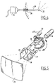
- a position pick-up means 10 is arranged in the form of a toroidal tube 11 which is made for example of plastic and around which is arranged a winding 12.
- a ball 15 Arranged in the hollow space of the toroidal tube 11 is a ball 15 which can rotate freely inside the tube and which will always occupy the lowest position as a result of the force of gravity.
- This position is sensed by the winding which transmits a relevant signal via the cable 13.
- This is transmitted to the image display device together with the signal representing the image transported via the cable 14.
- the image display device such an indication can be given for example by an arrow or a triangle on the top side of the displayed image. The surgeon for instance is thus informed that the displayed image is rotated relative to the horizontal.
- image pick-up units of which the image pick-up surface extends obliquely relative to the rotation axis of the pick-up unit.
- the displayed image will not only rotate but also change; the image pick-up units are "looking" the other way.
- the uncorrected signal together with the correction signal or the signal corrected using the correction signal can be stored in analog or digital form on a recording medium.
- FIG. 3 another embodiment of an image pick-up unit is shown. This is formed by an optical fibre 25 which leads to a video camera 26. A rotation pick-up means 27 is arranged on the engaging surface of the light conductor 25, so that in this situation rotations of the pick-up means in the form of the optical conductor can also be corrected.
- Fig. 4 shows a third embodiment of an image pick-up unit according to the invention.
- This embodiment is particularly suitable for applications with intra-abdominal endoscopic surgery.
- a laparoscope 29 is herein introduced into the abdominal cavity 30 by means of a trocar 28.
- the part of the laparoscope 29 remaining outside the abdominal cavity is situated in the vicinity of a camera 31, wherein it is possible to rotate the laparoscope 29 inside the trocar 28.
- This is important in the first instance in order to obtain different images from the laparoscope 29.
- the latter is in any case provided with an oblique pick-up surface 32 that looks away "obliquely”.
- a field of vision can thus be obtained which is formed by a collection of separate images, wherein the central lines of the images form a cone.
- the field of vision is hereby considerably enlarged compared to a situation where it is only possible to look "straight ahead". Instruments are often carried simultaneously by the same trocar, wherein the operations performed can be viewed carefully using the laparoscope. It should be otherwise noted that the laparoscope can rotate relative to the camera. In these situations a direction indication according to the invention is also of the greatest importance.
- the camera can also be fixed on the internal end of the laparoscope.
- FIG. 5 An example of an image display device is shown in fig. 5.
- This cathode ray tube comprises an electrode gun 16, a set of vertical deflecting plates 17, 18, and a set of horizontal deflecting plates 19, 20, which deflecting plates 17-20 are arranged together in a frame 21.
- This frame is arranged for rotation by means of a servomotor 22.
- the electron bundle coming from the electron gun 16 falls on a screen 23 and is reproduced there.
- the electric motor 22 With the signal coming from position pick-up means 10 the position of the plates 17-20 is corrected, so that the image reproduced on the display 23 assumes the correct position, and is corrected for rotation of the camera position. It will be apparent that the signal coming from the pick-up unit will have to be amplified before it is fed to the servomotor.
Landscapes
- Engineering & Computer Science (AREA)
- Health & Medical Sciences (AREA)
- Life Sciences & Earth Sciences (AREA)
- Surgery (AREA)
- Physics & Mathematics (AREA)
- Multimedia (AREA)
- Signal Processing (AREA)
- Biomedical Technology (AREA)
- Animal Behavior & Ethology (AREA)
- Pathology (AREA)
- Radiology & Medical Imaging (AREA)
- Nuclear Medicine, Radiotherapy & Molecular Imaging (AREA)
- Biophysics (AREA)
- Heart & Thoracic Surgery (AREA)
- Medical Informatics (AREA)
- Molecular Biology (AREA)
- Optics & Photonics (AREA)
- General Health & Medical Sciences (AREA)
- Public Health (AREA)
- Veterinary Medicine (AREA)
- General Physics & Mathematics (AREA)
- Radar, Positioning & Navigation (AREA)
- Remote Sensing (AREA)
- Endoscopes (AREA)
Abstract
Description
- The invention relates to a device for reproducing an image of a poorly accessible location, for example in a living body, comprising a substantially cylindrical image pick-up unit to be arranged at the location and an image display means connected to the image pick-up unit.
- Such devices, generally known in for example medical technology, are used for instance to reproduce images from inaccessible places of a living body. Such image pick-up units are herein pushed into the often narrow channels in a body, which channels may for example be formed by veins or arteries or intestines for example, so that the dimensions of such an image pick-up unit have to be very small, for example with a transverse dimension in the order of magnitude of a few millimetres.
- In respect of the usually substantially circular section of such channels such image pick-up units are likewise usually given a cylindrical form. With these cylindrical image pick-up units there is therefore the danger that they will rotate on their axis. When these image pick-up units rotate inside the channel, the image hereby picked up will likewise be transmitted to the image display means rotated relative to the horizontal. When no clear reference to the horizontal is present in the image, as is mostly the case when picking up images inside a body, the orientation of the image reproduced on the image display means is unknown.
- Resulting herefrom is therefore an image for which the transmitted information is incomplete.
- When the displayed image is used in performing an operation, dangerous situations can therefore arise. It is thus possible for instance that, as a result of the inaccurate display, an incision which is intended to extend between two intestines extends transversely along the intestines.
- In such applications it is known for example to have water drip in front of the camera so that a reference relative to the vertical, and therefore automatically also relative to the horizontal, is obtained. This is awkward however and nothing like possible in all situations.
- Attempts are also made, for example with the help of an assistant, to continuously maintain the position of the image pick-up unit on the basis of a known position.
- Another typical manner is to reciprocally move an endoscope in which a camera is situated. From the movement on the screen resulting herefrom the deviation of the angle relative to the horizontal can be determined. Correction can take place by rotation of the camera.
- The object of the present invention is to provide such a device, wherein the above stated problems are avoided.
- This object is achieved in that the image pick-up unit is provided with indication means for indicating the rotation position of the image pick-up unit on its axis relative to the horizontal.
- As a result of these steps it is possible to give an indication of the horizontal, or for example the vertical, on the image reproduced on the image display means, so that the orientation of the displayed image is known, or by processing the displayed image or by turning the image display means such that the orientation of the displayed image corresponds with the actual orientation.
- The invention will subsequently be elucidated with reference to the annexed drawings, in which:
- fig. 1 is a partly broken away view of a first embodiment of an image pick-up unit arranged in a channel in the body;
- fig. 2 is a partly broken away enlarged perspective view of the image pick-up unit depicted in fig. 1;
- fig. 3 shows a second embodiment of an image pick-up unit according to the present invention;
- fig. 4 shows a third embodiment of an image pick-up unit according to the present invention; and
- fig. 5 shows an embodiment of a reproducing device which is provided with a correction device according to the invention.
- In the situation depicted in fig. 1 a channel 1 is shown which is formed for example by a blood vessel in a human body. Situated in channel 1 is an image pick-
up unit 2 which is received in a cylindrical housing 3 and which transposes into acable 5 via a conical part 4. Alens 7 is arranged in thefront surface 6 of the image pick-up unit. As a result of the rotation symmetrical form of this image pick-up unit there is a danger that it will rotate inside the channel 1. - The pick-
up unit 2 is shown in more detail in fig. 2. It can be seen here that image pick-up unit 2 is provided with an image pick-up element 8 in the form of a CCD board which is connected to anelectronic circuit 9 located therebehind in which the signal is processed for transmitting thereof via thecable 5 to an image display device placed outside the body. - This image pick-up unit in the form of the shown video camera can of course be equipped with other components of less importance to the present invention, such as a displacing device for the lens in order to enable focussing of the image reproduced on the CCD element 8. In general the
lens 7 will therefore be formed by a lens assembly consisting of various elements. A form of diaphragm can also be arranged. - In order to prevent the problems referred to in the preamble a position pick-up means 10 is arranged in the form of a toroidal tube 11 which is made for example of plastic and around which is arranged a winding 12. Arranged in the hollow space of the toroidal tube 11 is a
ball 15 which can rotate freely inside the tube and which will always occupy the lowest position as a result of the force of gravity. This position is sensed by the winding which transmits a relevant signal via thecable 13. This is transmitted to the image display device together with the signal representing the image transported via thecable 14. In the image display device such an indication can be given for example by an arrow or a triangle on the top side of the displayed image. The surgeon for instance is thus informed that the displayed image is rotated relative to the horizontal. - It is of course possible to use other forms of rotation pick-up means.
- Use is also made of image pick-up units of which the image pick-up surface extends obliquely relative to the rotation axis of the pick-up unit. Herein, when the image pick-up units rotate, the displayed image will not only rotate but also change; the image pick-up units are "looking" the other way.
- Before the image is reproduced visually the uncorrected signal together with the correction signal or the signal corrected using the correction signal can be stored in analog or digital form on a recording medium.
- In fig. 3 another embodiment of an image pick-up unit is shown. This is formed by an
optical fibre 25 which leads to avideo camera 26. A rotation pick-up means 27 is arranged on the engaging surface of thelight conductor 25, so that in this situation rotations of the pick-up means in the form of the optical conductor can also be corrected. - Fig. 4 shows a third embodiment of an image pick-up unit according to the invention. This embodiment is particularly suitable for applications with intra-abdominal endoscopic surgery. A
laparoscope 29 is herein introduced into the abdominal cavity 30 by means of atrocar 28. The part of thelaparoscope 29 remaining outside the abdominal cavity is situated in the vicinity of acamera 31, wherein it is possible to rotate thelaparoscope 29 inside thetrocar 28. This is important in the first instance in order to obtain different images from thelaparoscope 29. The latter is in any case provided with an oblique pick-up surface 32 that looks away "obliquely". By rotating laparoscope 29 a field of vision can thus be obtained which is formed by a collection of separate images, wherein the central lines of the images form a cone. The field of vision is hereby considerably enlarged compared to a situation where it is only possible to look "straight ahead". Instruments are often carried simultaneously by the same trocar, wherein the operations performed can be viewed carefully using the laparoscope. It should be otherwise noted that the laparoscope can rotate relative to the camera. In these situations a direction indication according to the invention is also of the greatest importance. - It will otherwise be apparent that the camera can also be fixed on the internal end of the laparoscope.
- An example of an image display device is shown in fig. 5. This is formed by a cathode ray tube, the construction of which is assumed known. This cathode ray tube comprises an
electrode gun 16, a set ofvertical deflecting plates horizontal deflecting plates frame 21. This frame is arranged for rotation by means of aservomotor 22. The electron bundle coming from theelectron gun 16 falls on ascreen 23 and is reproduced there. By thus driving theelectric motor 22 with the signal coming from position pick-up means 10 the position of the plates 17-20 is corrected, so that the image reproduced on thedisplay 23 assumes the correct position, and is corrected for rotation of the camera position. It will be apparent that the signal coming from the pick-up unit will have to be amplified before it is fed to the servomotor. - It is likewise possible to rotate the entire picture tube or to process the signal representing the image such that the horizontal in the image is actually displayed horizontally.
Claims (14)
- Device for reproducing an image of a poorly accessible location in a living body, comprising a substantially cylindrical image pick-up unit (2) to be arranged at the location and an image display means connected to the image pick-up unit (2) by flexible connecting means (5, 14), which are adapted to extend at least partially through the body, characterized in that the image pick-up unit (2) is provided with indication means (10) for indicating the rotation position of the image pick-up unit (2) on its axis relative to the horizontal as a result of the force of gravity, and that the indication means (10) are adapted to generate a correction signal representing the rotation position.
- Device as claimed in claim 1, characterized in that the image pick-up unit (2) is adapted to receive light with at least a component in the axial direction of the pick-up unit (2).
- Device as claimed in claim 1 or 2, characterized in that the image display means (23) is provided with means (17-21) for correcting the position of the displayed image relative to the horizontal.
- Device as claimed in claim 1, 2 or 3, characterized in that the image pick-up unit (2) is a video camera (3, 7, 8, 9).
- Device as claimed in claim 4, characterized in that the image pick-up unit (2) is formed by the engaging surface of an optical fibre (25), which fibre leads to a video camera (26) disposed elsewhere.
- Device as claimed in claim 4 or 5, characterized in that the image pick-up unit (2) has an engaging surface (32) which extends at an angle differing from 90° relative to the axis of the pick-up unit (2).
- Device as claimed in claim 6, characterized in that the image pick-up unit (2) is rotatable around the pick-up axis.
- Device as claimed in claim 3, characterized in that the image display (23) has a display surface that is rotatable round a central axis relative to the rest of the display means.
- Device as claimed in claim 3, characterized in that the image display means is a cathode ray tube (23), the deflector (17-20) plates of which are rotatable round the symmetry axis between the deflector plates (17-20).
- Device as claimed in claim 3, characterized in that the image display means (23) is provided with electronic correction means for correcting the rotation position of the reproduced image, wherein the correction signal is fed to the correction means.
- Device as claimed in claim 3, characterized in that the image display means (23) is provided with indication means for indicating the rotation position of the displayed image.
- Device as claimed in any of the foregoing claims, characterized by a storage means for storing in a storage medium the signal coming from the image display means.
- Device as claimed in claim 12, characterized in that the storage means is adapted to store the signal together with the correction signal.
- Device as claimed in claim 12, characterized in that the storage means is adapted to store the signal corrected using the correction signal.
Applications Claiming Priority (3)
| Application Number | Priority Date | Filing Date | Title |
|---|---|---|---|
| NL9301210A NL9301210A (en) | 1993-07-09 | 1993-07-09 | Image display system with image position correction. |
| NL9301210 | 1993-07-09 | ||
| PCT/BE1994/000042 WO1995001749A1 (en) | 1993-07-09 | 1994-07-07 | Tv camera with rotational orientation correction |
Publications (2)
| Publication Number | Publication Date |
|---|---|
| EP0712289A1 EP0712289A1 (en) | 1996-05-22 |
| EP0712289B1 true EP0712289B1 (en) | 1997-05-02 |
Family
ID=19862640
Family Applications (1)
| Application Number | Title | Priority Date | Filing Date |
|---|---|---|---|
| EP94918697A Expired - Lifetime EP0712289B1 (en) | 1993-07-09 | 1994-07-07 | Tv camera with rotational orientation correction |
Country Status (6)
| Country | Link |
|---|---|
| US (1) | US5899851A (en) |
| EP (1) | EP0712289B1 (en) |
| JP (1) | JP3476195B2 (en) |
| AU (1) | AU6991794A (en) |
| NL (1) | NL9301210A (en) |
| WO (1) | WO1995001749A1 (en) |
Cited By (1)
| Publication number | Priority date | Publication date | Assignee | Title |
|---|---|---|---|---|
| US10769471B2 (en) | 2018-10-03 | 2020-09-08 | Karl Storz Se & Co. Kg | System and method for holding an image display apparatus |
Families Citing this family (78)
| Publication number | Priority date | Publication date | Assignee | Title |
|---|---|---|---|---|
| US5973734A (en) | 1997-07-09 | 1999-10-26 | Flashpoint Technology, Inc. | Method and apparatus for correcting aspect ratio in a camera graphical user interface |
| DE19804234C1 (en) * | 1998-02-04 | 1999-11-04 | Storz Karl Gmbh & Co | Endoscope, especially video endoscope |
| DE69922791T2 (en) * | 1998-02-19 | 2005-12-08 | California Institute Of Technology, Pasadena | DEVICE FOR PROVIDING A SPHERICAL SEA FIELD DURING ENDOSCOPIC INTERVENTION |
| US6317141B1 (en) | 1998-12-31 | 2001-11-13 | Flashpoint Technology, Inc. | Method and apparatus for editing heterogeneous media objects in a digital imaging device |
| US6902528B1 (en) * | 1999-04-14 | 2005-06-07 | Stereotaxis, Inc. | Method and apparatus for magnetically controlling endoscopes in body lumens and cavities |
| DE19924361C2 (en) * | 1999-05-27 | 2002-05-08 | Winter & Ibe Olympus | endoscope |
| GB9918703D0 (en) * | 1999-08-10 | 1999-10-13 | Scope Limited G | Laparoscopic camera control system |
| US7037258B2 (en) | 1999-09-24 | 2006-05-02 | Karl Storz Imaging, Inc. | Image orientation for endoscopic video displays |
| JP3917885B2 (en) * | 2002-04-08 | 2007-05-23 | オリンパス株式会社 | Capsule endoscope system |
| US20040199052A1 (en) | 2003-04-01 | 2004-10-07 | Scimed Life Systems, Inc. | Endoscopic imaging system |
| DE10314655B3 (en) * | 2003-04-01 | 2004-05-27 | Assfalg Qualitätshydraulik GmbH & Co. KG | Digital camera sensor device for determining artificial horizon using balls rotating within hollow toroidal body |
| US20050054895A1 (en) * | 2003-09-09 | 2005-03-10 | Hoeg Hans David | Method for using variable direction of view endoscopy in conjunction with image guided surgical systems |
| US7232409B2 (en) | 2003-11-20 | 2007-06-19 | Karl Storz Development Corp. | Method and apparatus for displaying endoscopic images |
| US7134992B2 (en) * | 2004-01-09 | 2006-11-14 | Karl Storz Development Corp. | Gravity referenced endoscopic image orientation |
| US9033871B2 (en) | 2004-04-07 | 2015-05-19 | Karl Storz Imaging, Inc. | Gravity referenced endoscopic image orientation |
| IL170404A (en) * | 2004-08-26 | 2012-03-29 | C2Cure Inc | Wireless determination of endoscope orientation |
| US7517314B2 (en) * | 2004-10-14 | 2009-04-14 | Karl Storz Development Corp. | Endoscopic imaging with indication of gravity direction |
| US7811224B2 (en) * | 2004-11-09 | 2010-10-12 | Karl Storz Development Corp. | Method for dealing with singularities in gravity referenced endoscopic imaging |
| US7221522B2 (en) * | 2005-01-28 | 2007-05-22 | Karl Storz Development Corp. | Optical system for variable direction of view instrument |
| US7967742B2 (en) * | 2005-02-14 | 2011-06-28 | Karl Storz Imaging, Inc. | Method for using variable direction of view endoscopy in conjunction with image guided surgical systems |
| US7956887B2 (en) * | 2005-02-17 | 2011-06-07 | Karl Storz Imaging, Inc. | Image orienting coupling assembly |
| DE602006015913D1 (en) | 2006-04-10 | 2010-09-16 | Storz Karl Dev Corp | Endoscopic imaging with indication of the direction of gravity |
| US9224145B1 (en) | 2006-08-30 | 2015-12-29 | Qurio Holdings, Inc. | Venue based digital rights using capture device with digital watermarking capability |
| US20080108870A1 (en) * | 2006-11-06 | 2008-05-08 | Wiita Bruce E | Apparatus and method for stabilizing an image from an endoscopic camera |
| DE102007009292A1 (en) | 2007-02-16 | 2008-08-21 | Karl Storz Gmbh & Co. Kg | Videoscope |
| GB2493606B (en) * | 2008-03-07 | 2013-03-27 | Milwaukee Electric Tool Corp | Visual inspection device |
| US8834358B2 (en) | 2009-03-27 | 2014-09-16 | EndoSphere Surgical, Inc. | Cannula with integrated camera and illumination |
| AU2010229709B2 (en) * | 2009-03-27 | 2015-02-05 | EndoSphere Surgical, Inc. | Cannula with integrated camera and illumination |
| US8495931B2 (en) | 2009-04-23 | 2013-07-30 | John S. Sroka | Ratchet wrench |
| EP2429376B1 (en) * | 2009-05-08 | 2016-10-19 | Boston Scientific Scimed, Inc. | Endoscope with distal tip having encased optical components and display orientation capabilities |
| US20110032368A1 (en) * | 2009-08-07 | 2011-02-10 | Nicholas John Pelling | System for Emulating Continuous Pan/Tilt Cameras |
| US8668638B2 (en) * | 2010-02-11 | 2014-03-11 | Intuitive Surgical Operations, Inc. | Method and system for automatically maintaining an operator selected roll orientation at a distal tip of a robotic endoscope |
| WO2011127223A1 (en) | 2010-04-06 | 2011-10-13 | Pavel Menn | Hermetic rotating handle assembly for a surgical clip applier for laparoscopic procedures |
| US9387048B2 (en) | 2011-10-14 | 2016-07-12 | Intuitive Surgical Operations, Inc. | Catheter sensor systems |
| US20130303944A1 (en) | 2012-05-14 | 2013-11-14 | Intuitive Surgical Operations, Inc. | Off-axis electromagnetic sensor |
| US9452276B2 (en) | 2011-10-14 | 2016-09-27 | Intuitive Surgical Operations, Inc. | Catheter with removable vision probe |
| US10238837B2 (en) | 2011-10-14 | 2019-03-26 | Intuitive Surgical Operations, Inc. | Catheters with control modes for interchangeable probes |
| US9118818B2 (en) * | 2012-06-26 | 2015-08-25 | Olympus Corporation | Endoscope apparatus, reproducing apparatus, displaying method and inspection report generating apparatus |
| US20140148673A1 (en) | 2012-11-28 | 2014-05-29 | Hansen Medical, Inc. | Method of anchoring pullwire directly articulatable region in catheter |
| EP2950701B1 (en) | 2013-02-01 | 2021-03-10 | DEKA Products Limited Partnership | Endoscope with pannable camera |
| US10616491B2 (en) | 2013-02-01 | 2020-04-07 | Deka Products Limited Partnership | Endoscope with pannable camera and related method |
| US9566414B2 (en) | 2013-03-13 | 2017-02-14 | Hansen Medical, Inc. | Integrated catheter and guide wire controller |
| US10849702B2 (en) | 2013-03-15 | 2020-12-01 | Auris Health, Inc. | User input devices for controlling manipulation of guidewires and catheters |
| US9283046B2 (en) | 2013-03-15 | 2016-03-15 | Hansen Medical, Inc. | User interface for active drive apparatus with finite range of motion |
| US11020016B2 (en) | 2013-05-30 | 2021-06-01 | Auris Health, Inc. | System and method for displaying anatomy and devices on a movable display |
| US20140375784A1 (en) * | 2013-06-21 | 2014-12-25 | Omnivision Technologies, Inc. | Image Sensor With Integrated Orientation Indicator |
| EP3689284B1 (en) | 2013-10-24 | 2025-02-26 | Auris Health, Inc. | System for robotic-assisted endolumenal surgery |
| EP2923669B1 (en) * | 2014-03-24 | 2017-06-28 | Hansen Medical, Inc. | Systems and devices for catheter driving instinctiveness |
| EP3200718B1 (en) | 2014-09-30 | 2026-02-18 | Auris Health, Inc. | Configurable robotic surgical system with virtual rail and flexible endoscope |
| US10314463B2 (en) | 2014-10-24 | 2019-06-11 | Auris Health, Inc. | Automated endoscope calibration |
| US12383120B2 (en) * | 2015-11-13 | 2025-08-12 | Daryl BODNER | Endoscope |
| US10143526B2 (en) | 2015-11-30 | 2018-12-04 | Auris Health, Inc. | Robot-assisted driving systems and methods |
| US11037464B2 (en) | 2016-07-21 | 2021-06-15 | Auris Health, Inc. | System with emulator movement tracking for controlling medical devices |
| US9931025B1 (en) * | 2016-09-30 | 2018-04-03 | Auris Surgical Robotics, Inc. | Automated calibration of endoscopes with pull wires |
| US10244926B2 (en) | 2016-12-28 | 2019-04-02 | Auris Health, Inc. | Detecting endolumenal buckling of flexible instruments |
| US10806326B2 (en) * | 2017-04-17 | 2020-10-20 | Olympus Corporation | Method for observing the branch portion of the hole and method for operating the endoscope system |
| US20180296070A1 (en) * | 2017-04-17 | 2018-10-18 | Olympus Corporation | Method for observing the branch portion of the hole and method for operating the endoscope system |
| JP7677608B2 (en) | 2017-05-12 | 2025-05-15 | オーリス ヘルス インコーポレイテッド | Biopsy Device and System |
| JP7130682B2 (en) | 2017-06-28 | 2022-09-05 | オーリス ヘルス インコーポレイテッド | instrument insertion compensation |
| US10426559B2 (en) | 2017-06-30 | 2019-10-01 | Auris Health, Inc. | Systems and methods for medical instrument compression compensation |
| US10145747B1 (en) | 2017-10-10 | 2018-12-04 | Auris Health, Inc. | Detection of undesirable forces on a surgical robotic arm |
| CN110831536B (en) | 2017-12-06 | 2021-09-07 | 奥瑞斯健康公司 | System and method for correcting for uncommanded instrument roll |
| CN110831534B (en) | 2017-12-08 | 2023-04-28 | 奥瑞斯健康公司 | Systems and methods for medical instrument navigation and targeting |
| WO2019118767A1 (en) | 2017-12-14 | 2019-06-20 | Auris Health, Inc. | System and method for estimating instrument location |
| MX2020008464A (en) | 2018-02-13 | 2020-12-07 | Auris Health Inc | SYSTEM AND METHOD TO ACTIVATE A MEDICAL INSTRUMENT. |
| EP3784109B1 (en) | 2018-04-26 | 2023-08-02 | DEKA Products Limited Partnership | Endoscope with rotatable camera |
| CN112218595B (en) | 2018-05-18 | 2026-04-03 | 奥瑞斯健康公司 | Controller for remote operation systems enabling robots |
| US11032481B2 (en) | 2018-07-06 | 2021-06-08 | Medos International Sarl | Camera scope electronic variable prism |
| US11202014B2 (en) | 2018-07-06 | 2021-12-14 | Medos International Sari | Camera scope electronic variable angle of view |
| JP7536752B2 (en) | 2018-09-28 | 2024-08-20 | オーリス ヘルス インコーポレイテッド | Systems and methods for endoscope-assisted percutaneous medical procedures - Patents.com |
| KR102852843B1 (en) | 2018-09-28 | 2025-09-03 | 아우리스 헬스, 인코포레이티드 | System and method for docking medical devices |
| EP3989793B1 (en) | 2019-06-28 | 2025-11-19 | Auris Health, Inc. | Surgical console interface |
| US11439429B2 (en) | 2019-07-11 | 2022-09-13 | New View Surgical | Cannula assembly with deployable camera |
| US11070745B2 (en) | 2019-10-28 | 2021-07-20 | Karl Storz Imaging, Inc. | Automatic image orientation based on use |
| KR20220123273A (en) | 2019-12-31 | 2022-09-06 | 아우리스 헬스, 인코포레이티드 | Anatomical feature identification and targeting |
| EP4084720A4 (en) | 2019-12-31 | 2024-01-17 | Auris Health, Inc. | Alignment techniques for percutaneous access |
| CN114929148B (en) | 2019-12-31 | 2024-05-10 | 奥瑞斯健康公司 | Alignment interface for percutaneous access |
| US11737663B2 (en) | 2020-03-30 | 2023-08-29 | Auris Health, Inc. | Target anatomical feature localization |
Citations (2)
| Publication number | Priority date | Publication date | Assignee | Title |
|---|---|---|---|---|
| EP0314475A1 (en) * | 1987-10-30 | 1989-05-03 | Shimizu Construction Co., Ltd. | Bore hole scanner |
| EP0501088A1 (en) * | 1991-02-21 | 1992-09-02 | Richard Wolf GmbH | Endoscope with proximal coupled camera |
Family Cites Families (19)
| Publication number | Priority date | Publication date | Assignee | Title |
|---|---|---|---|---|
| GB620088A (en) * | 1947-01-03 | 1949-03-18 | Michael Crowley Crowley Millin | Improvements relating to control apparatus for cathode ray tubes |
| US3525561A (en) * | 1968-10-10 | 1970-08-25 | Olympus Optical Co | Device for indicating the orientation of the image of an object in a fiber optical system |
| JPS5223975Y2 (en) * | 1973-05-29 | 1977-05-31 | ||
| JPS54154759U (en) * | 1978-04-20 | 1979-10-27 | ||
| DE2940931C2 (en) * | 1979-10-09 | 1986-05-07 | Siemens AG, 1000 Berlin und 8000 München | Deflection unit for cathode ray tubes |
| JPS58190913A (en) * | 1982-05-01 | 1983-11-08 | Olympus Optical Co Ltd | Strabismal hard endoscope |
| US4493155A (en) * | 1982-09-29 | 1985-01-15 | Combustion Engineering, Inc. | Apparatus for remotely indicating angular position |
| US4587741A (en) * | 1983-09-27 | 1986-05-13 | Develco, Inc. | Ball inclinometer |
| JPS6150546A (en) * | 1984-08-20 | 1986-03-12 | 富士写真光機株式会社 | Endoscope |
| US4752836A (en) * | 1984-09-07 | 1988-06-21 | Ivex Corporation | Method and apparatus for reproducing video images to simulate movement within a multi-dimensional space |
| JPS63270032A (en) * | 1987-04-30 | 1988-11-08 | Olympus Optical Co Ltd | Ultrasonic endoscope |
| US4928699A (en) * | 1987-05-18 | 1990-05-29 | Olympus Optical Co., Ltd. | Ultrasonic diagnosis device |
| JPH0796005B2 (en) * | 1987-10-27 | 1995-10-18 | オリンパス光学工業株式会社 | Endoscope device |
| US4902129A (en) * | 1988-09-06 | 1990-02-20 | Schott Fiber Optics | Orientation indicator for a flexible fiberscope or endoscope including method of manufacture |
| DE4001182C2 (en) * | 1989-01-17 | 1997-02-13 | Olympus Optical Co | Ultrasound diagnostic device |
| DE4102196C2 (en) * | 1990-01-26 | 2002-08-01 | Olympus Optical Co | Imaging device for tracking an object |
| JPH0490743A (en) * | 1990-08-02 | 1992-03-24 | Olympus Optical Co Ltd | Endoscope apparatus |
| JP3095835B2 (en) * | 1991-10-30 | 2000-10-10 | 株式会社町田製作所 | Gravity direction indicator for endoscopes |
| JP3067346B2 (en) * | 1991-10-30 | 2000-07-17 | 株式会社町田製作所 | Gravity direction indicator for endoscopes |
-
1993
- 1993-07-09 NL NL9301210A patent/NL9301210A/en not_active Application Discontinuation
-
1994
- 1994-07-07 EP EP94918697A patent/EP0712289B1/en not_active Expired - Lifetime
- 1994-07-07 US US08/591,471 patent/US5899851A/en not_active Expired - Lifetime
- 1994-07-07 JP JP50372295A patent/JP3476195B2/en not_active Expired - Lifetime
- 1994-07-07 AU AU69917/94A patent/AU6991794A/en not_active Abandoned
- 1994-07-07 WO PCT/BE1994/000042 patent/WO1995001749A1/en not_active Ceased
Patent Citations (3)
| Publication number | Priority date | Publication date | Assignee | Title |
|---|---|---|---|---|
| EP0314475A1 (en) * | 1987-10-30 | 1989-05-03 | Shimizu Construction Co., Ltd. | Bore hole scanner |
| EP0501088A1 (en) * | 1991-02-21 | 1992-09-02 | Richard Wolf GmbH | Endoscope with proximal coupled camera |
| US5307804A (en) * | 1991-02-21 | 1994-05-03 | Richard Wolf Gmbh | Endoscope having a camera coupled thereto |
Cited By (1)
| Publication number | Priority date | Publication date | Assignee | Title |
|---|---|---|---|---|
| US10769471B2 (en) | 2018-10-03 | 2020-09-08 | Karl Storz Se & Co. Kg | System and method for holding an image display apparatus |
Also Published As
| Publication number | Publication date |
|---|---|
| NL9301210A (en) | 1995-02-01 |
| JP3476195B2 (en) | 2003-12-10 |
| WO1995001749A1 (en) | 1995-01-19 |
| AU6991794A (en) | 1995-02-06 |
| EP0712289A1 (en) | 1996-05-22 |
| US5899851A (en) | 1999-05-04 |
| JPH08512223A (en) | 1996-12-24 |
Similar Documents
| Publication | Publication Date | Title |
|---|---|---|
| EP0712289B1 (en) | Tv camera with rotational orientation correction | |
| US8211008B2 (en) | Video endoscope | |
| EP2143374B1 (en) | Solid state variable direction of view endoscope | |
| US8758234B2 (en) | Solid state variable direction of view endoscope | |
| US5818527A (en) | Image processor for correcting distortion of central portion of image and preventing marginal portion of the image from protruding | |
| EP1685790A1 (en) | Endoscope device and imaging method using the same | |
| JP4955840B2 (en) | Stereoscopic endoscope | |
| JP3782532B2 (en) | Stereoscopic electronic endoscope | |
| JPWO2018003349A1 (en) | Endoscope device | |
| JPH10290777A (en) | Ultra wide-angle endoscope | |
| JP3504681B2 (en) | Electronic endoscope device | |
| JPH0850252A (en) | Stereoscopic picture forming assembly for endoscope inspection probe | |
| JP2945031B2 (en) | Ultrasound endoscope | |
| US10813543B2 (en) | Insertion portion of endoscope | |
| JP2552344B2 (en) | Electronic endoscopic device | |
| JPH11197096A (en) | Electronic endoscope device for magnified microscopic observation | |
| JPH10243919A (en) | Endoscope device | |
| JP3034905B2 (en) | Electronic endoscope | |
| JPH09122070A (en) | Skew type electronic endoscope | |
| EP2745763B1 (en) | Solid state variable direction of view endoscope | |
| CN115868915A (en) | Multi-camera electronic laparoscope and image processor | |
| JPS6311929Y2 (en) | ||
| JP2001037711A (en) | Endoscope device | |
| JPH09187419A (en) | Endoscope | |
| JPH0888791A (en) | Image pickup device |
Legal Events
| Date | Code | Title | Description |
|---|---|---|---|
| PUAI | Public reference made under article 153(3) epc to a published international application that has entered the european phase |
Free format text: ORIGINAL CODE: 0009012 |
|
| 17P | Request for examination filed |
Effective date: 19960126 |
|
| AK | Designated contracting states |
Kind code of ref document: A1 Designated state(s): FR GB IT |
|
| GRAG | Despatch of communication of intention to grant |
Free format text: ORIGINAL CODE: EPIDOS AGRA |
|
| 17Q | First examination report despatched |
Effective date: 19960619 |
|
| GRAH | Despatch of communication of intention to grant a patent |
Free format text: ORIGINAL CODE: EPIDOS IGRA |
|
| GRAH | Despatch of communication of intention to grant a patent |
Free format text: ORIGINAL CODE: EPIDOS IGRA |
|
| ITF | It: translation for a ep patent filed | ||
| GRAA | (expected) grant |
Free format text: ORIGINAL CODE: 0009210 |
|
| AK | Designated contracting states |
Kind code of ref document: B1 Designated state(s): FR GB IT |
|
| ET | Fr: translation filed | ||
| PLBE | No opposition filed within time limit |
Free format text: ORIGINAL CODE: 0009261 |
|
| STAA | Information on the status of an ep patent application or granted ep patent |
Free format text: STATUS: NO OPPOSITION FILED WITHIN TIME LIMIT |
|
| 26N | No opposition filed | ||
| REG | Reference to a national code |
Ref country code: GB Ref legal event code: IF02 |
|
| PGFP | Annual fee paid to national office [announced via postgrant information from national office to epo] |
Ref country code: GB Payment date: 20130626 Year of fee payment: 20 |
|
| PGFP | Annual fee paid to national office [announced via postgrant information from national office to epo] |
Ref country code: FR Payment date: 20130722 Year of fee payment: 20 |
|
| PGFP | Annual fee paid to national office [announced via postgrant information from national office to epo] |
Ref country code: IT Payment date: 20130628 Year of fee payment: 20 |
|
| REG | Reference to a national code |
Ref country code: GB Ref legal event code: PE20 Expiry date: 20140706 |
|
| PG25 | Lapsed in a contracting state [announced via postgrant information from national office to epo] |
Ref country code: GB Free format text: LAPSE BECAUSE OF EXPIRATION OF PROTECTION Effective date: 20140706 |