EP0713016A1 - Coupling device - Google Patents
Coupling device Download PDFInfo
- Publication number
- EP0713016A1 EP0713016A1 EP95203159A EP95203159A EP0713016A1 EP 0713016 A1 EP0713016 A1 EP 0713016A1 EP 95203159 A EP95203159 A EP 95203159A EP 95203159 A EP95203159 A EP 95203159A EP 0713016 A1 EP0713016 A1 EP 0713016A1
- Authority
- EP
- European Patent Office
- Prior art keywords
- coupling
- coupling part
- piece
- male
- female
- Prior art date
- Legal status (The legal status is an assumption and is not a legal conclusion. Google has not performed a legal analysis and makes no representation as to the accuracy of the status listed.)
- Granted
Links
- 230000008878 coupling Effects 0.000 title claims abstract description 125
- 238000010168 coupling process Methods 0.000 title claims abstract description 125
- 238000005859 coupling reaction Methods 0.000 title claims abstract description 125
- 230000002093 peripheral effect Effects 0.000 claims abstract description 4
- 230000000903 blocking effect Effects 0.000 claims 1
- 230000037431 insertion Effects 0.000 description 1
- 238000003780 insertion Methods 0.000 description 1
Images

Classifications
-
- A—HUMAN NECESSITIES
- A45—HAND OR TRAVELLING ARTICLES
- A45F—TRAVELLING OR CAMP EQUIPMENT: SACKS OR PACKS CARRIED ON THE BODY
- A45F5/00—Holders or carriers for hand articles; Holders or carriers for use while travelling or camping
- A45F5/02—Fastening articles to the garment
- A45F5/021—Fastening articles to the garment to the belt
-
- A—HUMAN NECESSITIES
- A45—HAND OR TRAVELLING ARTICLES
- A45F—TRAVELLING OR CAMP EQUIPMENT: SACKS OR PACKS CARRIED ON THE BODY
- A45F5/00—Holders or carriers for hand articles; Holders or carriers for use while travelling or camping
- A45F5/02—Fastening articles to the garment
-
- F—MECHANICAL ENGINEERING; LIGHTING; HEATING; WEAPONS; BLASTING
- F16—ENGINEERING ELEMENTS AND UNITS; GENERAL MEASURES FOR PRODUCING AND MAINTAINING EFFECTIVE FUNCTIONING OF MACHINES OR INSTALLATIONS; THERMAL INSULATION IN GENERAL
- F16B—DEVICES FOR FASTENING OR SECURING CONSTRUCTIONAL ELEMENTS OR MACHINE PARTS TOGETHER, e.g. NAILS, BOLTS, CIRCLIPS, CLAMPS, CLIPS OR WEDGES; JOINTS OR JOINTING
- F16B21/00—Means for preventing relative axial movement of a pin, spigot, shaft or the like and a member surrounding it; Stud-and-socket releasable fastenings
- F16B21/02—Releasable fastening devices locking by rotation
-
- H—ELECTRICITY
- H04—ELECTRIC COMMUNICATION TECHNIQUE
- H04B—TRANSMISSION
- H04B1/00—Details of transmission systems, not covered by a single one of groups H04B3/00 - H04B13/00; Details of transmission systems not characterised by the medium used for transmission
- H04B1/38—Transceivers, i.e. devices in which transmitter and receiver form a structural unit and in which at least one part is used for functions of transmitting and receiving
- H04B1/3827—Portable transceivers
- H04B1/3888—Arrangements for carrying or protecting transceivers
-
- A—HUMAN NECESSITIES
- A45—HAND OR TRAVELLING ARTICLES
- A45F—TRAVELLING OR CAMP EQUIPMENT: SACKS OR PACKS CARRIED ON THE BODY
- A45F5/00—Holders or carriers for hand articles; Holders or carriers for use while travelling or camping
- A45F5/02—Fastening articles to the garment
- A45F2005/025—Fastening articles to the garment with a holder or item rotatably connected to the fastening device, e.g. having a rotation axis perpendicular to the garment
- A45F2005/026—Fastening articles to the garment with a holder or item rotatably connected to the fastening device, e.g. having a rotation axis perpendicular to the garment with a pin having an enlarged head detachably connected to a fastening device, e.g. to a pin receiving slot
-
- H—ELECTRICITY
- H04—ELECTRIC COMMUNICATION TECHNIQUE
- H04B—TRANSMISSION
- H04B1/00—Details of transmission systems, not covered by a single one of groups H04B3/00 - H04B13/00; Details of transmission systems not characterised by the medium used for transmission
- H04B1/38—Transceivers, i.e. devices in which transmitter and receiver form a structural unit and in which at least one part is used for functions of transmitting and receiving
- H04B1/3827—Portable transceivers
- H04B1/385—Transceivers carried on the body, e.g. in helmets
Definitions
- the invention relates to a coupling which comprises: a male coupling part which is formed by a base with a protrusion and hereon a coupling piece extending above the base; and a female coupling part with a recess in which a passage for the coupling piece is defined by at least one flange, wherein in coupled situation the male coupling part is inserted into the female coupling part for rotation on a rotation axis of the male coupling part such that the or more than one flange is at least partially arranged between the base and the coupling piece.
- Such couplings are known wherein the coupling piece is formed with two or more than two axes of symmetry intersecting the rotation axis.
- Such a coupling according to the known art has the drawback that the male coupling part, in two or more than two different positions relative to the female coupling part, is detachable therefrom as a result of the form of the coupling piece according to the known art.
- the positions in which the male coupling part is detachable from the female coupling part are uniformly distributed over the turning circle of the male coupling part when it is rotated relative to the female coupling part.
- the drawback hereof is that when the male coupling part is rotated relative to the female coupling part undesired release can take place. This is a particular drawback in the case where the coupling is used for example to couple a holder for telecommunication apparatus, such as a portable telephone, to a trouser belt, wherein such an undesired release can result in damage to the apparatus placed in the holder.
- the invention has for its object to obviate the above stated drawbacks and provides to this end a coupling which is distinguished in that the peripheral shape of the coupling piece is symmetrical relative to a maximum of one axis of symmetry intersecting the rotation axis.
- the male coupling part can only be placed into the female coupling part in one relative position, wherein this position is such that undesired release cannot occur.
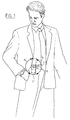
- FIG 1 is shown an application of a coupling according to the present invention, wherein a holder 1 for a telecommunications apparatus for example, such as a portable telephone or a semaphone, is coupled to a belt 2 of the user thereof by means of a coupling according to the present invention.
- a holder 1 for a telecommunications apparatus for example, such as a portable telephone or a semaphone
- a male coupling part fixed to the holder 1 is placed into a female coupling part fastened to the belt 2, when the holder is situated in the position indicated by dashed lines.
- the holder 1 is then turned on the rotation axis defined by the coupling to the position shown in the figure with full lines. In this latter position the holder can move freely in the directions indicated by the arrows A and B, wherein there is no danger of the holder 1 being released from the belt 2.
- the holder 1 can only be released from the belt 2 when holder 1 is again turned to the position shown by means of the dashed lines.
- the holder 1 Since in this embodiment of the coupling the holder 1 can swing freely in the directions indicated by means of the arrows A and B, the wearer of the holder 1 will experience very little hindrance from the holder 1 when for example he is walking or sits down.
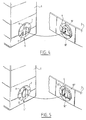
- the coupling shown in figure 2 comprises: a male coupling part 5 with a base in the form of a disc 7, a cylindrical protrusion 8 and a coupling piece in the form of hexagonal plate 9; and a female coupling part in the form of a flat ring 6, wherein flanges 10 are arranged on the inside of the flat ring 6.
- the shape of the passage defined by the flanges 10 in the inside of the flat ring 6 corresponds closely with the outer periphery of the hexagonal plate 9.
- the shape of the hexagonal plate 9 corresponds with that of a scalene triangle, the inscribed circle of which coincides with the outer periphery of the cylindrical protrusion 8, and the points of which are cut off along a circle concentric with the cylindrical protrusion.
- the periphery of this circle corresponds with the inner wall of the flat ring 6. It is noted here that a scalene triangle, and also a scalene triangle of which parts have been cut off in this manner, does not have an axis of symmetry perpendicular to the rotation axis.
- the rotation axis around which the male coupling part 5 is rotatable in the flat ring 6 coincides in this configuration of the coupling with the central axis of the cylindrical protrusion 8 and with the middle of the disc 7.
- the holder 1 is then rotated a half turn through the coupling, whereafter the holder 1 hangs on the belt 2 by means of the coupling.
- FIG 3 shows a section of the coupling in a coupled situation taken along the surface of the flat ring 6 facing toward the male coupling part 5. It is apparent that the male coupling part 5 can only be placed into the female coupling part in the form of flat ring 6 in one relative position, and that release can also only be effected in this same relative position.
- Figure 4 is a view corresponding with figure 2 of another embodiment of a coupling according to the present invention.
- the coupling shown differs from that shown in figure 2 in the shape of the coupling piece 11 and the shape of the flanges 10 corresponding therewith.
- the coupling piece has the form of a disc which corresponds with the cylindrical protrusion 8 and to which are fixed two flanges with a curvature corresponding with the inside wall of the flat ring 6, wherein the coupling piece 11 is symmetrical relative to a vertical axis of symmetry in the representation shown in the figure, which intersects the axis of rotation.
- the coupling piece has no other axis of symmetry.
- a third embodiment of a coupling according to the present invention is shown in figure 5.
- the shape of the coupling piece 12 in this embodiment is that of a semi-ellipse obtained by cutting along a line perpendicular to the lengthwise axis, wherein the circle inscribed in this semi-ellipse corresponds with the periphery cylindrical protrusion 8. It is here also the case that the form of the coupling piece 12 only has one axis of symmetry intersecting and perpendicular to the axis of rotation, whereby coupling and release of the coupling can only take place in one relative position of the male coupling part 5 relative to the flat ring 6.
- the coupling is provided with locking means, such as a cavity placed in accordance with a desired locking position in the surface of the base directed toward the female coupling part and a bulge corresponding therewith on the surface of the female coupling part directed toward the male coupling part, or vice versa.
- locking means such as a cavity placed in accordance with a desired locking position in the surface of the base directed toward the female coupling part and a bulge corresponding therewith on the surface of the female coupling part directed toward the male coupling part, or vice versa.
- both the male coupling part and the female coupling part are formed in each case by flat components.
- the base of the male coupling part is convex and the female coupling part has a concave shape corresponding therewith, or vice versa.
- the coupling piece it is also possible for the coupling piece to have other than a plate shape, such as a part of a sphere. If the side of the female coupling part facing away from the base of the male coupling part is covered with a cover plate, the cover plate in this latter case must have a concave form.
- the parts of the coupling piece extending above the base of the male coupling part are directed toward the base.
- the protrusion has a shape other than cylindrical.
- the invention also comprises shapes whereof the central axis lies at a distance relative to the rotation axis around which the male coupling part rotates in the female coupling part in the coupled situation.
- the coupling piece is preferably formed such that in any position other than the insertion position it hooks behind flanges to such a degree that tilting of the male coupling part in and relative to the female coupling part is prevented.
Landscapes
- Engineering & Computer Science (AREA)
- General Engineering & Computer Science (AREA)
- Mechanical Engineering (AREA)
- Computer Networks & Wireless Communication (AREA)
- Signal Processing (AREA)
- Snaps, Bayonet Connections, Set Pins, And Snap Rings (AREA)
- Quick-Acting Or Multi-Walled Pipe Joints (AREA)
- Clamps And Clips (AREA)
- Telephone Set Structure (AREA)
Abstract
Description
- The invention relates to a coupling which comprises: a male coupling part which is formed by a base with a protrusion and hereon a coupling piece extending above the base; and a female coupling part with a recess in which a passage for the coupling piece is defined by at least one flange, wherein in coupled situation the male coupling part is inserted into the female coupling part for rotation on a rotation axis of the male coupling part such that the or more than one flange is at least partially arranged between the base and the coupling piece.
- Such couplings are known wherein the coupling piece is formed with two or more than two axes of symmetry intersecting the rotation axis.
- Such a coupling according to the known art has the drawback that the male coupling part, in two or more than two different positions relative to the female coupling part, is detachable therefrom as a result of the form of the coupling piece according to the known art. Herein the positions in which the male coupling part is detachable from the female coupling part are uniformly distributed over the turning circle of the male coupling part when it is rotated relative to the female coupling part.
- The drawback hereof is that when the male coupling part is rotated relative to the female coupling part undesired release can take place. This is a particular drawback in the case where the coupling is used for example to couple a holder for telecommunication apparatus, such as a portable telephone, to a trouser belt, wherein such an undesired release can result in damage to the apparatus placed in the holder.
- The invention has for its object to obviate the above stated drawbacks and provides to this end a coupling which is distinguished in that the peripheral shape of the coupling piece is symmetrical relative to a maximum of one axis of symmetry intersecting the rotation axis.
- With a coupling according to the present invention the male coupling part can only be placed into the female coupling part in one relative position, wherein this position is such that undesired release cannot occur.
- The invention will be further elucidated with reference to the figure description of a number of embodiments of the invention following hereinbelow. In the drawing:
- figure 1 shows an illustration of an application of a coupling according to the present invention;
- figure 2 shows a perspective view of coupling parts of a coupling according to the present invention;
- figure 3 shows a sectional view of the coupling parts shown in figure 2 in coupled situation;
- figure 4 shows a second embodiment of the coupling according to the invention; and
- figure 5 shows a third embodiment of the coupling according to the present invention.
- In figure 1 is shown an application of a coupling according to the present invention, wherein a holder 1 for a telecommunications apparatus for example, such as a portable telephone or a semaphone, is coupled to a
belt 2 of the user thereof by means of a coupling according to the present invention. - A male coupling part fixed to the holder 1 is placed into a female coupling part fastened to the
belt 2, when the holder is situated in the position indicated by dashed lines. The holder 1 is then turned on the rotation axis defined by the coupling to the position shown in the figure with full lines. In this latter position the holder can move freely in the directions indicated by the arrows A and B, wherein there is no danger of the holder 1 being released from thebelt 2. The holder 1 can only be released from thebelt 2 when holder 1 is again turned to the position shown by means of the dashed lines. - Since in this embodiment of the coupling the holder 1 can swing freely in the directions indicated by means of the arrows A and B, the wearer of the holder 1 will experience very little hindrance from the holder 1 when for example he is walking or sits down.
- The coupling shown in figure 2 comprises: a
male coupling part 5 with a base in the form of adisc 7, acylindrical protrusion 8 and a coupling piece in the form ofhexagonal plate 9; and a female coupling part in the form of aflat ring 6, whereinflanges 10 are arranged on the inside of theflat ring 6. - The shape of the passage defined by the
flanges 10 in the inside of theflat ring 6 corresponds closely with the outer periphery of thehexagonal plate 9. The shape of thehexagonal plate 9 corresponds with that of a scalene triangle, the inscribed circle of which coincides with the outer periphery of thecylindrical protrusion 8, and the points of which are cut off along a circle concentric with the cylindrical protrusion. The periphery of this circle corresponds with the inner wall of theflat ring 6. It is noted here that a scalene triangle, and also a scalene triangle of which parts have been cut off in this manner, does not have an axis of symmetry perpendicular to the rotation axis. - When the
hexagonal plate 9 of themale coupling part 5 is therefore placed into theflat ring 6, the parts of the periphery of thehexagonal plate 9 corresponding with the cut-off parts of the scalene triangle connect to the inside wall of theflat ring 6 and thecylindrical protrusion 8 is enclosed on three sides by theflanges 10. - The rotation axis around which the
male coupling part 5 is rotatable in theflat ring 6 coincides in this configuration of the coupling with the central axis of thecylindrical protrusion 8 and with the middle of thedisc 7. When thehexagonal plate 9 of themale coupling part 5 is therefore placed through the passage in theflat ring 6 defined by theflanges 10 and themale coupling part 5 is rotated, thedisc 7 and theflat ring 6 will only rotate relative to each other, wherein no other relative movement takes place. - The holder 1 is then rotated a half turn through the coupling, whereafter the holder 1 hangs on the
belt 2 by means of the coupling. - This situation is shown in figure 3, which figure shows a section of the coupling in a coupled situation taken along the surface of the
flat ring 6 facing toward themale coupling part 5. It is apparent that themale coupling part 5 can only be placed into the female coupling part in the form offlat ring 6 in one relative position, and that release can also only be effected in this same relative position. - Figure 4 is a view corresponding with figure 2 of another embodiment of a coupling according to the present invention. The coupling shown differs from that shown in figure 2 in the shape of the
coupling piece 11 and the shape of theflanges 10 corresponding therewith. - The coupling piece has the form of a disc which corresponds with the
cylindrical protrusion 8 and to which are fixed two flanges with a curvature corresponding with the inside wall of theflat ring 6, wherein thecoupling piece 11 is symmetrical relative to a vertical axis of symmetry in the representation shown in the figure, which intersects the axis of rotation. The coupling piece has no other axis of symmetry. Once again themale coupling part 5 can therefore only be placed into theflat ring 6 in one relative position, and release can only be effected in this same relative position. - A third embodiment of a coupling according to the present invention is shown in figure 5. The shape of the
coupling piece 12 in this embodiment is that of a semi-ellipse obtained by cutting along a line perpendicular to the lengthwise axis, wherein the circle inscribed in this semi-ellipse corresponds with the peripherycylindrical protrusion 8. It is here also the case that the form of thecoupling piece 12 only has one axis of symmetry intersecting and perpendicular to the axis of rotation, whereby coupling and release of the coupling can only take place in one relative position of themale coupling part 5 relative to theflat ring 6. - In a preferred embodiment of the invention the coupling is provided with locking means, such as a cavity placed in accordance with a desired locking position in the surface of the base directed toward the female coupling part and a bulge corresponding therewith on the surface of the female coupling part directed toward the male coupling part, or vice versa.
- In the above described embodiments of couplings according to the present invention both the male coupling part and the female coupling part are formed in each case by flat components. In other embodiments of the invention it is however possible that the base of the male coupling part is convex and the female coupling part has a concave shape corresponding therewith, or vice versa. It is also possible for the coupling piece to have other than a plate shape, such as a part of a sphere. If the side of the female coupling part facing away from the base of the male coupling part is covered with a cover plate, the cover plate in this latter case must have a concave form.
- In another embodiment of a coupling according to the present invention the parts of the coupling piece extending above the base of the male coupling part are directed toward the base.
- In yet another embodiment of a coupling according to the present invention the protrusion has a shape other than cylindrical. The invention also comprises shapes whereof the central axis lies at a distance relative to the rotation axis around which the male coupling part rotates in the female coupling part in the coupled situation.
- In an embodiment of the invention the coupling piece is preferably formed such that in any position other than the insertion position it hooks behind flanges to such a degree that tilting of the male coupling part in and relative to the female coupling part is prevented.
Claims (7)
- Coupling, which comprises: a male coupling part which is formed by a base with a protrusion and hereon a coupling piece extending above the base; and a female coupling part with a recess in which a passage for the coupling piece is defined by at least one flange, wherein in coupled situation the male coupling part is inserted in the female coupling part for rotation on a rotation axis of the male coupling part such that the or more than one flange is at least partially arranged between the base and the coupling piece, characterized in that the peripheral shape of the coupling piece is symmetrical relative to a maximum of one axis of symmetry intersecting the rotation axis.
- Coupling as claimed in claim 1, characterized in that the periphery of the protrusion is placed at least partially against the inner edge of the passage forming a bearing in a coupled situation of the coupling.
- Coupling as claimed in claim 1 or 2, characterized in that the peripheral edge of the coupling piece is placed at least partially against the inner wall of the recess forming a bearing in a coupled situation of the coupling.
- Coupling as claimed in any of the foregoing claims, characterized in that the protrusion is substantially covered by the coupling piece.
- Coupling as claimed in any of the foregoing claims, characterized in that the periphery of the coupling piece is substantially formed by a triangle with unequal sides.
- Coupling as claimed in any of the foregoing claims, characterized in that at least a part of the periphery of the coupling piece is formed by cutting off the parts lying outside the shape corresponding with the inner circle of the recess.
- Coupling as claimed in any of the foregoing claims, characterized by locking means for blocking the rotation in at least one position of the male coupling part relative to the female locking part.
Applications Claiming Priority (4)
| Application Number | Priority Date | Filing Date | Title |
|---|---|---|---|
| NL9401924 | 1994-11-17 | ||
| NL9401924 | 1994-11-17 | ||
| NL9500234A NL192999C (en) | 1994-11-17 | 1995-02-08 | Link. |
| NL9500234 | 1995-02-08 |
Publications (2)
| Publication Number | Publication Date |
|---|---|
| EP0713016A1 true EP0713016A1 (en) | 1996-05-22 |
| EP0713016B1 EP0713016B1 (en) | 2002-05-29 |
Family
ID=26647277
Family Applications (1)
| Application Number | Title | Priority Date | Filing Date |
|---|---|---|---|
| EP95203159A Expired - Lifetime EP0713016B1 (en) | 1994-11-17 | 1995-11-17 | Coupling device |
Country Status (5)
| Country | Link |
|---|---|
| EP (1) | EP0713016B1 (en) |
| DE (1) | DE69526836T2 (en) |
| ES (1) | ES2177603T3 (en) |
| NL (1) | NL192999C (en) |
| PT (1) | PT713016E (en) |
Cited By (4)
| Publication number | Priority date | Publication date | Assignee | Title |
|---|---|---|---|---|
| WO1999029208A1 (en) * | 1997-12-11 | 1999-06-17 | Lucent Technologies Inc. | Clothing attachment device for portable equipment |
| EP2058325A2 (en) | 1998-04-16 | 2009-05-13 | Institut Pasteur | A method for isolating a polynucleotide of interest from the genome of a mycobacterium using a BAC-based DNA library. application to the detection of mycobacteria |
| US12613557B2 (en) | 2012-01-12 | 2026-04-28 | Rokform Ip Llc | Case and mount system for handheld electronic device |
| US12630247B2 (en) | 2023-07-31 | 2026-05-19 | Rokform Ip Llc | Electronic device mount |
Citations (6)
| Publication number | Priority date | Publication date | Assignee | Title |
|---|---|---|---|---|
| GB1187430A (en) * | 1967-08-22 | 1970-04-08 | Painton & Co Ltd | Improvements in or relating to Quick Release Fasteners and Components Combined with such Fasteners |
| US3743147A (en) * | 1970-12-10 | 1973-07-03 | Motorola Inc | Support for carrying case |
| US4605335A (en) * | 1985-02-28 | 1986-08-12 | Otrusina Edward C | Quick-release connector with teardrop-shaped configuration |
| WO1992004548A1 (en) * | 1990-08-29 | 1992-03-19 | Donaldson Company, Inc. | Quarter turn fastener |
| EP0568921A1 (en) * | 1992-05-05 | 1993-11-10 | ROCKINGER Spezialfabrik für Anhängerkupplungen GmbH & Co. | Coupling device |
| DE9417826U1 (en) * | 1994-11-07 | 1995-01-12 | Rubin, Edvard, Stara Nova Vas | Mobile phone case |
-
1995
- 1995-02-08 NL NL9500234A patent/NL192999C/en not_active IP Right Cessation
- 1995-11-17 DE DE1995626836 patent/DE69526836T2/en not_active Expired - Fee Related
- 1995-11-17 PT PT95203159T patent/PT713016E/en unknown
- 1995-11-17 EP EP95203159A patent/EP0713016B1/en not_active Expired - Lifetime
- 1995-11-17 ES ES95203159T patent/ES2177603T3/en not_active Expired - Lifetime
Patent Citations (6)
| Publication number | Priority date | Publication date | Assignee | Title |
|---|---|---|---|---|
| GB1187430A (en) * | 1967-08-22 | 1970-04-08 | Painton & Co Ltd | Improvements in or relating to Quick Release Fasteners and Components Combined with such Fasteners |
| US3743147A (en) * | 1970-12-10 | 1973-07-03 | Motorola Inc | Support for carrying case |
| US4605335A (en) * | 1985-02-28 | 1986-08-12 | Otrusina Edward C | Quick-release connector with teardrop-shaped configuration |
| WO1992004548A1 (en) * | 1990-08-29 | 1992-03-19 | Donaldson Company, Inc. | Quarter turn fastener |
| EP0568921A1 (en) * | 1992-05-05 | 1993-11-10 | ROCKINGER Spezialfabrik für Anhängerkupplungen GmbH & Co. | Coupling device |
| DE9417826U1 (en) * | 1994-11-07 | 1995-01-12 | Rubin, Edvard, Stara Nova Vas | Mobile phone case |
Cited By (4)
| Publication number | Priority date | Publication date | Assignee | Title |
|---|---|---|---|---|
| WO1999029208A1 (en) * | 1997-12-11 | 1999-06-17 | Lucent Technologies Inc. | Clothing attachment device for portable equipment |
| EP2058325A2 (en) | 1998-04-16 | 2009-05-13 | Institut Pasteur | A method for isolating a polynucleotide of interest from the genome of a mycobacterium using a BAC-based DNA library. application to the detection of mycobacteria |
| US12613557B2 (en) | 2012-01-12 | 2026-04-28 | Rokform Ip Llc | Case and mount system for handheld electronic device |
| US12630247B2 (en) | 2023-07-31 | 2026-05-19 | Rokform Ip Llc | Electronic device mount |
Also Published As
| Publication number | Publication date |
|---|---|
| PT713016E (en) | 2002-10-31 |
| NL192999C (en) | 1998-07-03 |
| DE69526836T2 (en) | 2002-11-28 |
| NL192999B (en) | 1998-03-02 |
| DE69526836D1 (en) | 2002-07-04 |
| ES2177603T3 (en) | 2002-12-16 |
| NL9500234A (en) | 1996-07-01 |
| EP0713016B1 (en) | 2002-05-29 |
Similar Documents
| Publication | Publication Date | Title |
|---|---|---|
| US6021526A (en) | Hearing protection device | |
| US20030037366A1 (en) | Hearing protection device | |
| US4453050A (en) | Earphone | |
| EP1003349A3 (en) | Flexible earhook | |
| US11241329B2 (en) | Ostomy device | |
| US3787899A (en) | Ear muff assembly | |
| USD438788S1 (en) | Star-shaped package | |
| EP0461148B1 (en) | Telephone support device | |
| US5904688A (en) | Orthopaedic assembly including an acetabular cup and cup inserter | |
| JP2000279419A (en) | Self-holding type surgical retractor being re- constitution possible | |
| EP0747026B1 (en) | Self-aligning ostomy device | |
| AU731231B2 (en) | Multi-position banded earmuff | |
| JPH03113006A (en) | Ratchet device for adjusting band and suspensory device for suspending head protecting helmet | |
| GB2220819A (en) | Electroacoustic transducer | |
| WO1996002368A1 (en) | Shaving apparatus | |
| JPH09307983A (en) | Earphone type handset | |
| EP0195035A4 (en) | Hand surgery table. | |
| US3813499A (en) | Hearing aid nozzle with resilient bayonet lock | |
| EP0713016B1 (en) | Coupling device | |
| GB1579875A (en) | Coupling for an ostomy bag | |
| SK282839B6 (en) | Clamping device | |
| USD292797S (en) | Telephone set | |
| EP0347025A2 (en) | Coupling for attaching an ostomy pouch to a medical grade adhesive pad | |
| EP1674792B1 (en) | Swivel support, eg. for lights | |
| GB2097854A (en) | A ball and socket joint |
Legal Events
| Date | Code | Title | Description |
|---|---|---|---|
| PUAI | Public reference made under article 153(3) epc to a published international application that has entered the european phase |
Free format text: ORIGINAL CODE: 0009012 |
|
| AK | Designated contracting states |
Kind code of ref document: A1 Designated state(s): BE CH DE ES FR GB LI NL PT |
|
| 17P | Request for examination filed |
Effective date: 19961111 |
|
| 17Q | First examination report despatched |
Effective date: 19980708 |
|
| GRAG | Despatch of communication of intention to grant |
Free format text: ORIGINAL CODE: EPIDOS AGRA |
|
| GRAG | Despatch of communication of intention to grant |
Free format text: ORIGINAL CODE: EPIDOS AGRA |
|
| GRAH | Despatch of communication of intention to grant a patent |
Free format text: ORIGINAL CODE: EPIDOS IGRA |
|
| GRAH | Despatch of communication of intention to grant a patent |
Free format text: ORIGINAL CODE: EPIDOS IGRA |
|
| GRAA | (expected) grant |
Free format text: ORIGINAL CODE: 0009210 |
|
| AK | Designated contracting states |
Kind code of ref document: B1 Designated state(s): BE CH DE ES FR GB LI NL PT |
|
| REG | Reference to a national code |
Ref country code: GB Ref legal event code: FG4D |
|
| REG | Reference to a national code |
Ref country code: CH Ref legal event code: NV Representative=s name: ARNOLD & SIEDSMA AG Ref country code: CH Ref legal event code: EP |
|
| REF | Corresponds to: |
Ref document number: 69526836 Country of ref document: DE Date of ref document: 20020704 |
|
| ET | Fr: translation filed | ||
| REG | Reference to a national code |
Ref country code: PT Ref legal event code: SC4A Free format text: AVAILABILITY OF NATIONAL TRANSLATION Effective date: 20020809 |
|
| PG25 | Lapsed in a contracting state [announced via postgrant information from national office to epo] |
Ref country code: GB Free format text: LAPSE BECAUSE OF NON-PAYMENT OF DUE FEES Effective date: 20021117 |
|
| PGFP | Annual fee paid to national office [announced via postgrant information from national office to epo] |
Ref country code: FR Payment date: 20021128 Year of fee payment: 8 Ref country code: ES Payment date: 20021128 Year of fee payment: 8 |
|
| PGFP | Annual fee paid to national office [announced via postgrant information from national office to epo] |
Ref country code: CH Payment date: 20021129 Year of fee payment: 8 |
|
| REG | Reference to a national code |
Ref country code: ES Ref legal event code: FG2A Ref document number: 2177603 Country of ref document: ES Kind code of ref document: T3 |
|
| PLBE | No opposition filed within time limit |
Free format text: ORIGINAL CODE: 0009261 |
|
| STAA | Information on the status of an ep patent application or granted ep patent |
Free format text: STATUS: NO OPPOSITION FILED WITHIN TIME LIMIT |
|
| 26N | No opposition filed |
Effective date: 20030303 |
|
| GBPC | Gb: european patent ceased through non-payment of renewal fee | ||
| PG25 | Lapsed in a contracting state [announced via postgrant information from national office to epo] |
Ref country code: ES Free format text: LAPSE BECAUSE OF NON-PAYMENT OF DUE FEES Effective date: 20031118 |
|
| PG25 | Lapsed in a contracting state [announced via postgrant information from national office to epo] |
Ref country code: LI Free format text: LAPSE BECAUSE OF NON-PAYMENT OF DUE FEES Effective date: 20031130 Ref country code: CH Free format text: LAPSE BECAUSE OF NON-PAYMENT OF DUE FEES Effective date: 20031130 |
|
| PG25 | Lapsed in a contracting state [announced via postgrant information from national office to epo] |
Ref country code: PT Free format text: LAPSE BECAUSE OF NON-PAYMENT OF DUE FEES Effective date: 20040531 |
|
| REG | Reference to a national code |
Ref country code: CH Ref legal event code: PL |
|
| PG25 | Lapsed in a contracting state [announced via postgrant information from national office to epo] |
Ref country code: FR Free format text: LAPSE BECAUSE OF NON-PAYMENT OF DUE FEES Effective date: 20040730 |
|
| REG | Reference to a national code |
Ref country code: PT Ref legal event code: MM4A Free format text: LAPSE DUE TO NON-PAYMENT OF FEES Effective date: 20040531 |
|
| REG | Reference to a national code |
Ref country code: FR Ref legal event code: ST |
|
| REG | Reference to a national code |
Ref country code: ES Ref legal event code: FD2A Effective date: 20031118 |
|
| PGFP | Annual fee paid to national office [announced via postgrant information from national office to epo] |
Ref country code: BE Payment date: 20061127 Year of fee payment: 12 |
|
| PGFP | Annual fee paid to national office [announced via postgrant information from national office to epo] |
Ref country code: NL Payment date: 20061130 Year of fee payment: 12 Ref country code: DE Payment date: 20061130 Year of fee payment: 12 |
|
| BERE | Be: lapsed |
Owner name: LEDERVERWERKENDE INDUSTRIE DE *BUFFEL B.V. Effective date: 20071130 |
|
| PG25 | Lapsed in a contracting state [announced via postgrant information from national office to epo] |
Ref country code: PT Free format text: LAPSE BECAUSE OF NON-PAYMENT OF DUE FEES Effective date: 20021117 |
|
| NLV4 | Nl: lapsed or anulled due to non-payment of the annual fee |
Effective date: 20080601 |
|
| PG25 | Lapsed in a contracting state [announced via postgrant information from national office to epo] |
Ref country code: BE Free format text: LAPSE BECAUSE OF NON-PAYMENT OF DUE FEES Effective date: 20071130 |
|
| PG25 | Lapsed in a contracting state [announced via postgrant information from national office to epo] |
Ref country code: NL Free format text: LAPSE BECAUSE OF NON-PAYMENT OF DUE FEES Effective date: 20080601 Ref country code: DE Free format text: LAPSE BECAUSE OF NON-PAYMENT OF DUE FEES Effective date: 20080603 |