EP0713087A1 - Apparatus and process for rapid and ultrasensitive detection and counting of microorganisms by fluorescence - Google Patents
Apparatus and process for rapid and ultrasensitive detection and counting of microorganisms by fluorescence Download PDFInfo
- Publication number
- EP0713087A1 EP0713087A1 EP94402610A EP94402610A EP0713087A1 EP 0713087 A1 EP0713087 A1 EP 0713087A1 EP 94402610 A EP94402610 A EP 94402610A EP 94402610 A EP94402610 A EP 94402610A EP 0713087 A1 EP0713087 A1 EP 0713087A1
- Authority
- EP
- European Patent Office
- Prior art keywords
- features
- correlated
- events
- microorganisms
- solid support
- Prior art date
- Legal status (The legal status is an assumption and is not a legal conclusion. Google has not performed a legal analysis and makes no representation as to the accuracy of the status listed.)
- Granted
Links
- 244000005700 microbiome Species 0.000 title claims abstract description 74
- 238000000034 method Methods 0.000 title claims abstract description 49
- 230000008569 process Effects 0.000 title abstract description 21
- 238000001514 detection method Methods 0.000 title description 20
- 239000007787 solid Substances 0.000 claims abstract description 48
- 230000000717 retained effect Effects 0.000 claims abstract description 16
- 239000000523 sample Substances 0.000 claims description 47
- 239000012528 membrane Substances 0.000 claims description 22
- 230000002596 correlated effect Effects 0.000 claims description 17
- 238000012545 processing Methods 0.000 claims description 9
- 230000000875 corresponding effect Effects 0.000 claims description 8
- 239000000975 dye Substances 0.000 claims description 6
- 230000036961 partial effect Effects 0.000 claims description 6
- 238000006243 chemical reaction Methods 0.000 claims description 4
- 238000002372 labelling Methods 0.000 claims description 4
- 230000010355 oscillation Effects 0.000 claims description 4
- 230000035899 viability Effects 0.000 claims description 4
- 239000007850 fluorescent dye Substances 0.000 claims description 3
- 102000004190 Enzymes Human genes 0.000 claims description 2
- 108090000790 Enzymes Proteins 0.000 claims description 2
- 230000001580 bacterial effect Effects 0.000 claims description 2
- 238000001816 cooling Methods 0.000 claims description 2
- 239000000126 substance Substances 0.000 claims description 2
- 230000001360 synchronised effect Effects 0.000 claims description 2
- 239000002210 silicon-based material Substances 0.000 claims 1
- 239000002245 particle Substances 0.000 description 10
- 238000004458 analytical method Methods 0.000 description 9
- 230000003287 optical effect Effects 0.000 description 6
- 241000894006 Bacteria Species 0.000 description 5
- 238000003384 imaging method Methods 0.000 description 5
- 230000001965 increasing effect Effects 0.000 description 5
- 230000035945 sensitivity Effects 0.000 description 5
- 239000003550 marker Substances 0.000 description 4
- 230000002829 reductive effect Effects 0.000 description 4
- 238000005070 sampling Methods 0.000 description 4
- XLYOFNOQVPJJNP-UHFFFAOYSA-N water Substances O XLYOFNOQVPJJNP-UHFFFAOYSA-N 0.000 description 4
- 238000013461 design Methods 0.000 description 3
- 239000000428 dust Substances 0.000 description 3
- 239000011148 porous material Substances 0.000 description 3
- 230000004044 response Effects 0.000 description 3
- 230000005679 Peltier effect Effects 0.000 description 2
- 230000008901 benefit Effects 0.000 description 2
- 239000000356 contaminant Substances 0.000 description 2
- 230000000694 effects Effects 0.000 description 2
- 238000005516 engineering process Methods 0.000 description 2
- 238000002474 experimental method Methods 0.000 description 2
- 230000012010 growth Effects 0.000 description 2
- 239000000463 material Substances 0.000 description 2
- 238000005259 measurement Methods 0.000 description 2
- 208000019331 Foodborne disease Diseases 0.000 description 1
- 108010043121 Green Fluorescent Proteins Proteins 0.000 description 1
- FAPWRFPIFSIZLT-UHFFFAOYSA-M Sodium chloride Chemical compound [Na+].[Cl-] FAPWRFPIFSIZLT-UHFFFAOYSA-M 0.000 description 1
- DPKHZNPWBDQZCN-UHFFFAOYSA-N acridine orange free base Chemical compound C1=CC(N(C)C)=CC2=NC3=CC(N(C)C)=CC=C3C=C21 DPKHZNPWBDQZCN-UHFFFAOYSA-N 0.000 description 1
- 230000003698 anagen phase Effects 0.000 description 1
- 238000013459 approach Methods 0.000 description 1
- 244000052616 bacterial pathogen Species 0.000 description 1
- 230000006399 behavior Effects 0.000 description 1
- DZBUGLKDJFMEHC-UHFFFAOYSA-N benzoquinolinylidene Natural products C1=CC=CC2=CC3=CC=CC=C3N=C21 DZBUGLKDJFMEHC-UHFFFAOYSA-N 0.000 description 1
- 230000033228 biological regulation Effects 0.000 description 1
- 239000012472 biological sample Substances 0.000 description 1
- 235000012206 bottled water Nutrition 0.000 description 1
- 239000008366 buffered solution Substances 0.000 description 1
- 235000013351 cheese Nutrition 0.000 description 1
- 230000001427 coherent effect Effects 0.000 description 1
- 230000001010 compromised effect Effects 0.000 description 1
- 238000004624 confocal microscopy Methods 0.000 description 1
- 238000011109 contamination Methods 0.000 description 1
- 238000012937 correction Methods 0.000 description 1
- 238000012258 culturing Methods 0.000 description 1
- 238000007405 data analysis Methods 0.000 description 1
- 238000013500 data storage Methods 0.000 description 1
- 230000003247 decreasing effect Effects 0.000 description 1
- 230000014670 detection of bacterium Effects 0.000 description 1
- 239000003651 drinking water Substances 0.000 description 1
- 230000003670 easy-to-clean Effects 0.000 description 1
- 238000000295 emission spectrum Methods 0.000 description 1
- 150000002148 esters Chemical class 0.000 description 1
- 238000011156 evaluation Methods 0.000 description 1
- 230000005284 excitation Effects 0.000 description 1
- 238000005562 fading Methods 0.000 description 1
- GNBHRKFJIUUOQI-UHFFFAOYSA-N fluorescein Chemical compound O1C(=O)C2=CC=CC=C2C21C1=CC=C(O)C=C1OC1=CC(O)=CC=C21 GNBHRKFJIUUOQI-UHFFFAOYSA-N 0.000 description 1
- 238000002189 fluorescence spectrum Methods 0.000 description 1
- 235000013305 food Nutrition 0.000 description 1
- 238000005286 illumination Methods 0.000 description 1
- 238000010191 image analysis Methods 0.000 description 1
- 238000011534 incubation Methods 0.000 description 1
- 230000001939 inductive effect Effects 0.000 description 1
- 238000003780 insertion Methods 0.000 description 1
- 230000037431 insertion Effects 0.000 description 1
- 230000000670 limiting effect Effects 0.000 description 1
- 230000004807 localization Effects 0.000 description 1
- 230000007246 mechanism Effects 0.000 description 1
- 230000002503 metabolic effect Effects 0.000 description 1
- 238000012543 microbiological analysis Methods 0.000 description 1
- 235000016046 other dairy product Nutrition 0.000 description 1
- 239000000825 pharmaceutical preparation Substances 0.000 description 1
- 229940127557 pharmaceutical product Drugs 0.000 description 1
- 230000002035 prolonged effect Effects 0.000 description 1
- 230000005180 public health Effects 0.000 description 1
- 238000011084 recovery Methods 0.000 description 1
- 230000009467 reduction Effects 0.000 description 1
- 229910052710 silicon Inorganic materials 0.000 description 1
- 239000010703 silicon Substances 0.000 description 1
- 239000011780 sodium chloride Substances 0.000 description 1
- 239000000243 solution Substances 0.000 description 1
- 238000013190 sterility testing Methods 0.000 description 1
- 238000012360 testing method Methods 0.000 description 1
- 238000013519 translation Methods 0.000 description 1
- 230000000007 visual effect Effects 0.000 description 1
Images





Classifications
-
- G—PHYSICS
- G01—MEASURING; TESTING
- G01N—INVESTIGATING OR ANALYSING MATERIALS BY DETERMINING THEIR CHEMICAL OR PHYSICAL PROPERTIES
- G01N15/00—Investigating characteristics of particles; Investigating permeability, pore-volume or surface-area of porous materials
- G01N15/10—Investigating individual particles
- G01N15/14—Optical investigation techniques, e.g. flow cytometry
- G01N15/1468—Optical investigation techniques, e.g. flow cytometry with spatial resolution of the texture or inner structure of the particle
-
- Y—GENERAL TAGGING OF NEW TECHNOLOGICAL DEVELOPMENTS; GENERAL TAGGING OF CROSS-SECTIONAL TECHNOLOGIES SPANNING OVER SEVERAL SECTIONS OF THE IPC; TECHNICAL SUBJECTS COVERED BY FORMER USPC CROSS-REFERENCE ART COLLECTIONS [XRACs] AND DIGESTS
- Y10—TECHNICAL SUBJECTS COVERED BY FORMER USPC
- Y10S—TECHNICAL SUBJECTS COVERED BY FORMER USPC CROSS-REFERENCE ART COLLECTIONS [XRACs] AND DIGESTS
- Y10S435/00—Chemistry: molecular biology and microbiology
- Y10S435/968—High energy substrates, e.g. fluorescent, chemiluminescent, radioactive
-
- Y—GENERAL TAGGING OF NEW TECHNOLOGICAL DEVELOPMENTS; GENERAL TAGGING OF CROSS-SECTIONAL TECHNOLOGIES SPANNING OVER SEVERAL SECTIONS OF THE IPC; TECHNICAL SUBJECTS COVERED BY FORMER USPC CROSS-REFERENCE ART COLLECTIONS [XRACs] AND DIGESTS
- Y10—TECHNICAL SUBJECTS COVERED BY FORMER USPC
- Y10S—TECHNICAL SUBJECTS COVERED BY FORMER USPC CROSS-REFERENCE ART COLLECTIONS [XRACs] AND DIGESTS
- Y10S436/00—Chemistry: analytical and immunological testing
- Y10S436/80—Fluorescent dyes, e.g. rhodamine
-
- Y—GENERAL TAGGING OF NEW TECHNOLOGICAL DEVELOPMENTS; GENERAL TAGGING OF CROSS-SECTIONAL TECHNOLOGIES SPANNING OVER SEVERAL SECTIONS OF THE IPC; TECHNICAL SUBJECTS COVERED BY FORMER USPC CROSS-REFERENCE ART COLLECTIONS [XRACs] AND DIGESTS
- Y10—TECHNICAL SUBJECTS COVERED BY FORMER USPC
- Y10T—TECHNICAL SUBJECTS COVERED BY FORMER US CLASSIFICATION
- Y10T436/00—Chemistry: analytical and immunological testing
- Y10T436/10—Composition for standardization, calibration, simulation, stabilization, preparation or preservation; processes of use in preparation for chemical testing
- Y10T436/101666—Particle count or volume standard or control [e.g., platelet count standards, etc.]
Definitions
- the present invention relates to an apparatus for rapid, ultrasensitive and automatic counting of fluorescent biological cells such as microorganims, carried by a solid support such as a filter and to a process for said rapid count of said microorganisms by said apparatus.
- the growth period provides at one time, the distinction between viable and non-viable organisms, as well as the magnification of the signals from the viable organisms, to facilitate their detection at low concentration.
- Rapid methods have been developed which are based on measuring the consequence of the metabolic activity of the microorganisms on a bulk property of the sample, such as impedance. All of these methods, called indirect methods, suffer from reduced sensitivity and still require culturing when the detection of low levels of contamination is required.
- DEFT direct epifluorescent filter techniques
- the sample to be analyzed is caused to pass through a filter which retains the microorganisms.
- the microorganisms are then made fluorescent and counted by visually analyzing the filter surface with an epifluorescence microscope.
- particles of interest are generally labelled with a fluorescent dye, such as acridine orange or other more specific dyes.
- An additional problem with the DEFT technique is discrimination between the searched microorganisms and other particles, which are naturally fluorescent, that may have also been concentrated on the filter.
- the repeatability and accuracy of the DEFT method are generally lower than that of the plate count methods.
- Other limitations of the DEFT include, low sensitivity, fading of intensity and operator fatigue, from prolonged use of the microscope.
- the resultant image is made up of individual picture elements (pixels).
- pixels picture elements
- even the best video cameras can only form images of as many as 100,000 or 1 million pixels.
- the diameter of a single microorganism is typically around 1 ⁇ m while the diameter of the filter is 25,000 ⁇ m.
- one pixel to be the size of a microorganism, it would take 625 million pixels to cover the entire filter.
- Another known means to improve the DEFT technique which may be considered is the use of a scanning confocal epifluorescence microscope.
- a small laser spot is used to sequentially illuminate each element of the image field, while a detector positioned behind a small pinhole is also focused on the same element.
- the image is then formed from the detector signals in a manner similar to that described above for an electronic imaging system.
- the dimensions of the illuminating spot is less than or equal to the dimensions of the smallest particle to be detected, and the dimensions of the pinhole is equal to or smaller than the dimensions of the illuminating spot.
- the present invention relates to an apparatus and a process capable of rapid and complete counts of fluorescent microorganisms such as those that might be trapped on the filter in the DEFT technique.
- the entire surface of the solid support such as a filter membrane is scanned with a laser beam and the fluorescence emitted measured at one or more wavelengths.
- the drawbacks described above are overcome through the use of a different and unique scanning pattern in combination with a unique means of processing the extensive detector signal data obtained in scanning the entire filter.
- a larger scanning spot is used together with an overlapping scan pattern which act together to maintain the sensitivity typically associated with a smaller spot while permitting a rapid scan.
- the present invention avoids both false negative and false positive results. It provides a process to fully discriminate wanted from unwanted signals, resulting in an accurate and fast counting of microorganisms present on a solid support of large dimension (typically 25 mm diameter), even at very low numbers.
- the invention has the potential to unequivocally detect down to one microorganism on the filter.
- the probability of detection for N independent scan passes over a target is proportional to the square root of N times the probability of detection for a single pass.
- the probability of detection for a single pass is in turn inversely proportional to the speed at which the pass is made.
- scanning the field twice, at twice the speed is equivalent in probability of detection to scanning once and no net gain in scan time is realized.
- the two passes are added in time synchrony, they are no longer independent trials, and a signal event, (which will be correlated between the two passes), will be favored over a noise event, (which will be uncorrelated).
- a signal event which will be correlated between the two passes
- an increased scanning rate is accomplished, for instance, by scanning with a large laser spot (see figure 1), and overlapping the scan, such that each element in the field is scanned at least twice.
- the results of each adjacent pair of scans in the X direction are then compared in time synchrony for the purpose of maintaining the probability of detection by eliminating uncorrelated signals.
- each positive event is correlated between two or more scan lines, (depending on the size of the fluorescent object).
- the fluorescence light emitted is measured continously by one or more detectors (at various wavelengths).
- the analog signal coming out of the detectors is digitalized by taking its value at constant frequency intervals.
- Reading a reading is the value of the signal at the time of measurement.
- Sample a sample is defined as a reading of the signal from the detector which exceeds a given dynamic threshold.
- Feature a set of adjacent samples on one scan line is called a feature.
- Line to line correlation 2 samples are said to be correlated when they appear in time synchrony on two adjacent scan lines.
- Single feature a feature which appears on only one scan line, ie which is not correlated, is called a single feature.
- Fluorescent spot fluorescence emitted by any fluorescent particle when excited by a laser beam. These particles can be microorganisms or other elements such as dust.
- the particles can be autofluorescent or have been made fluorescent for the detection (for example, microorganisms).
- Event is a set of at least two features which are correlated in time synchrony on adjacent scan lines.
- An event is the translation of a fluorescent spot in the measurement process.
- An event may subsequently be classified by the discriminator as either a positive event (ie an event being searched, such as a microorganism) or as a noise event (ie an event to be rejected as due to fluorescence generated for example by autofluorescent particles).
- a positive event ie an event being searched, such as a microorganism
- a noise event ie an event to be rejected as due to fluorescence generated for example by autofluorescent particles.
- a noise event if included in the final count, would give false positives.
- Laser spot light spot formed by a laser beam on a solid support.
- Interline or line spacing Y distance between two scanning lines.
- a method for counting fluorescent microorganisms on a solid support (or specimen support) such as a filter membrane is provided.
- Said method is characterized in that it comprises:
- the instant process comprises evaluating the number of scan lines covered by one event (width) and the number of samples forming the length of the event; this latter number deriving from accumulated count of samples from the start of the feature occuring the earliest in a scan-line in the scan direction, and the end of the feature which terminates the latest in a scan line, counting as one any sample appearing at the same location on 2 or more adjacent lines. Events are eliminated if comprising such overall sample count length greater than a predetermined number A, and a number of scan-lines greater than a predetermined number B (refer to figure 2).
- said size discrimination is carried out by:
- the instant process is characterized in that it comprises:
- said size discrimination is carried out by:
- the distance between two scanning lines is less than half the dimension of said laser spot size, leading to an overlap of the scanned surface.
- the step of detecting the resulting fluorescent light is performed by measuring signals exceeding a dynamic threshold, by means of a digital signal processor (DSP).
- DSP digital signal processor
- Said DSP allows to differentiate between wanted signals (corresponding to microorganisms) and some unwanted signals (electronic noise for instance).
- the instant analysis technique makes use of the size of the object to detect only in the following two ways:
- an apparatus for detection and counting of microorganisms by fluorescence on a solid support is provided.
- Said apparatus allows that the entire surface of the solid support is scanned.
- said scanning means comprises a first oscillating mirror, the axis of oscillation of which is perpendicular to the axis of the light beam for scanning a line by the beam; and a second mirror, the axis of which is perpendicular to the axis of oscillation of the first mirror, said second mirror executing a scanning movement synchronized with the scanning movement of said first mirror.
- said detecting means includes at least two photomultipliers as a means for the photoelectric conversion.
- said laser spot has an elongated shape.
- said solid support is a filter membrane.
- said sample holder cooperates with cooling means, such as ones leading to Peltier effect.
- a thin layer of a material such as silicon may be sandwiched between said sample holder and said filter membrane.
- Said thin layer has, for instance, the following advantages: no autofluorescence, low light reflexion at the excitation wavelength and easy to clean.
- Figure 11 provides the setting of the instrument and the number of events detected and reported (19 in this experiment).
- Figure 12 shows the localisation of the microorganisms.
- an apparatus comprising scanning means 10, means for detecting the emitted fluorescence, including dichroic filters 20, optical filters 21, photomultipliers (PMT) 30, a signal processing system 40-42, a digital signal processor 43, an instrument PC 50, a user PC 60 and an automated microscope 70.
- scanning means 10 means for detecting the emitted fluorescence, including dichroic filters 20, optical filters 21, photomultipliers (PMT) 30, a signal processing system 40-42, a digital signal processor 43, an instrument PC 50, a user PC 60 and an automated microscope 70.
- PMT photomultipliers
- the scanning device 10 uses coherent light to scan a solid support 11, represented by a filter membrane, carried on a membrane holder 8.
- the components of the scanning device 10 include a 488 nm argon-ion water cooled laser 12, scan mirrors 16, scanning lens 17 and a beam dump 18 which is a safety feature; said scanning means cooperates with means for focusing said laser beam into a laser spot comprising a beam expander 13 which controls the illuminating spot size to 4-14 ⁇ m, preferably 7 ⁇ m, and directs the illuminating spot onto said scan mirrors 16.
- Said beam expander 13 comprises two lenses, adapted (focal distance and distance between said two lenses), such as providing a laser spot on said solid support from 4 to 14 ⁇ m; for instance, to obtain a laser spot of 7 ⁇ m, focal distance of lens n°1 is 50 mm, focal distance of lens n°2 is 10 mm and the distance between the 2 lenses is 35,7 mm.
- Said two scanning mirrors are used to scan the illuminating laser spot across the solid support 11 on which is deposited the sample containing the microorganisms to be detected.
- the laser spot moves in the x direction at a speed for example of 1 meter per second.
- Said scanning mirrors 16 allow, for instance, a line-to-line (y) spacing of 3 ⁇ m (distance between two scan lines).
- a 25 mm filter can be scanned in under 3 minutes.
- the solid support 11 (such as a filter membrane) on which is deposited the sample to be analyzed is placed on a removable sample holder, which is used to carry the specimen support from the laboratory, or from where ever the sample is collected, and to introduce it into the instant apparatus.
- the load drawer (not represented) is easily accessible to the user.
- the removable sample holder is designed to handle, for instance, a circular solid support and is deposited on the load drawer. The drawer is then pushed into the apparatus and the sample membrane carrying the microorganisms comes directly under the scanner 16. The sample membrane holder is cooled to protect the stability of the labelled microorganism (for instance by Peltier effect).
- Said sample loader cooperates with a mechanism to introduce the sample holder in the apparatus and to automatically bring it with precision at the right distance from the scanning lenses.
- the scanner 16 passes the focused laser beam to the target 11, thereby inducing fluorescence from the microorganisms or any fluorescent material.
- the thus fluorescent light emitted from the sample membrane passes through dichroic filters 20 and optical filters 21 to two photomultipliers (PMTs) 30.
- PMTs photomultipliers
- Said PMTs 30 detect fluorescence at two wavelengths referred to as the green and the red channels) (centred on 530 nm and 615 nm).
- the PMT signals, together with time synchrony information from the scanner 16, are passed to the signal processing system 40.
- This system 40 comprises pre-amplifiers 41, signal sampling devices 42 and digital signal processing unit 43.
- each of said PMT signals is amplified by a dedicated preamplifier 41.
- the amplified analogue signals are digitally sampled at 2 MHz, using 8-bit resolution (256 signal levels).
- Each PMT channel has a dedicated sampler.
- the sampled PMT signals are passed to a Digital Signal Processor (DSP) 43.
- DSP Digital Signal Processor
- the signals are then analyzed and the resulting output information is passed through an instrument PC 50, which controls the scanning device, acts as a host for the DSP system 43, stores data during solid support scanning and passes scan results to the user PC 60.
- instrument PC 50 which controls the scanning device, acts as a host for the DSP system 43, stores data during solid support scanning and passes scan results to the user PC 60.
- Said user PC system 60 is used to process and display the results of a scan, currently using Matlab® software, as the principal analytical tool.
- the instant apparatus has the facility to allow, if necessary, direct observation of any object on the solid support, by driving an automated microscope from the user PC 60.
- FIG. 4-8 sum up the different steps of the instant process in view to reject:
- the target 11 is scanned as shown in figure 1.
- the scan time in terms of laser spot dimension and the SNR may be evaluated as follows:
- the signal is proportional to the intensity of illumination (watts/sq.cm.) and the time that each spot is illuminated.
- the noise is proportional to the square root of the illuminated area and inversely proportional to the scan velocity.
- the signal to noise can be expressed in terms of familiar quantities: This demonstrates explicitly how the detection signal to noise is reduced as either the scan speed or laser spot dimension is increased. Even though this equation does not consider the recovery of signal to noise which will be gained by correlation of adjacent scan lines (see figure 1).
- Figure 10 shows a comparison of the results of the two equations developed above, under two sets of conditions. In each case, it was assumed that an initial condition existed with a circular laser spot of dimension a. Under this condition, the SNR was 100% and the scan time was 100%.
- EXAMPLE 1 Detection of total viable bacteria in water.
- EXAMPLE 2 Detection and counting of fluorescent viable bacteria.
- the resulting fluorescent labelled microorganims are detected and counted by carrying out the instant process with the parameters illustrated in the following table IV and which can vary according to the type of microorganisms tested.
Landscapes
- Chemical & Material Sciences (AREA)
- Dispersion Chemistry (AREA)
- Physics & Mathematics (AREA)
- Health & Medical Sciences (AREA)
- Life Sciences & Earth Sciences (AREA)
- Analytical Chemistry (AREA)
- Biochemistry (AREA)
- General Health & Medical Sciences (AREA)
- General Physics & Mathematics (AREA)
- Immunology (AREA)
- Pathology (AREA)
- Investigating, Analyzing Materials By Fluorescence Or Luminescence (AREA)
- Apparatus Associated With Microorganisms And Enzymes (AREA)
- Measuring Or Testing Involving Enzymes Or Micro-Organisms (AREA)
Abstract
Description
- The present invention relates to an apparatus for rapid, ultrasensitive and automatic counting of fluorescent biological cells such as microorganims, carried by a solid support such as a filter and to a process for said rapid count of said microorganisms by said apparatus.
- The analysis of biological samples, food samples, potable water samples and pharmaceutical products for the presence of microorganisms is important and has important ramifications for safety, quality regulations and public health. For instance, recent oubtbreaks of food borne illness, implicating cheese and other dairy products contaminated with pathogenic bacteria, underscore the need for rapid methods for microbiological analysis.
- In the traditionnal plate technique, a sample to be analyzed is cultured and the resulting colonies counted. The results of the test are obtained after a growth period ranging from a minimum of 1 day to as much as 7 to 8 days. In this technique, the growth period provides at one time, the distinction between viable and non-viable organisms, as well as the magnification of the signals from the viable organisms, to facilitate their detection at low concentration.
- There is a crucial need for more rapid, more sensitive and more automated methods, for industrial as well as medical applications.
- Rapid methods have been developed which are based on measuring the consequence of the metabolic activity of the microorganisms on a bulk property of the sample, such as impedance. All of these methods, called indirect methods, suffer from reduced sensitivity and still require culturing when the detection of low levels of contamination is required.
- Other methods based on the direct counting of microorganisms have been developed recently. Among these, the direct epifluorescent filter techniques (DEFT) may be cited. In this technique the sample to be analyzed is caused to pass through a filter which retains the microorganisms. The microorganisms are then made fluorescent and counted by visually analyzing the filter surface with an epifluorescence microscope. In this method, particles of interest are generally labelled with a fluorescent dye, such as acridine orange or other more specific dyes.
- The visual analysis is tedious and complicated: first, because in the absence of a growth phase the organisms are quite small (requiring high power magnification for their detection), and second because the total area of the filter is so large that an impractical number of high power fields are required to cover the whole filter. Thus, typically only a small part of the filter is visually examined (less than 10%). This makes the technique inappropriate for sterility testing, where one single microorganism on the total filter has to be detected.
- An additional problem with the DEFT technique is discrimination between the searched microorganisms and other particles, which are naturally fluorescent, that may have also been concentrated on the filter.
- As a result of these problems, the repeatability and accuracy of the DEFT method are generally lower than that of the plate count methods. Other limitations of the DEFT include, low sensitivity, fading of intensity and operator fatigue, from prolonged use of the microscope.
- The use of the epifluorescent microscope fitted with an image analyzer, in view to improve the DEFT technique has also been reported. However, although this is effective in eliminating subjectivity and operator fatigue, it is still limited by the fundamental problem that the organisms are small and the area to be covered is large.
- In order to better understand this problem, it is useful to note that in electronic imaging systems the resultant image is made up of individual picture elements (pixels). In the current state of the art of electronic imaging, even the best video cameras can only form images of as many as 100,000 or 1 million pixels. However, the diameter of a single microorganism is typically around 1 µm while the diameter of the filter is 25,000 µm. Thus, if we consider one pixel to be the size of a microorganism, it would take 625 million pixels to cover the entire filter.
- As a result either a single picture element (pixel) must be made much larger than the dimensions of a single microorganism or the analysis must include many sequential images. However, neither of these approaches is satisfactory. In the first case, the sensitivity of detection is lowered while, in the second case the time and complexity of analysis are limiting factors.
- Another known means to improve the DEFT technique which may be considered is the use of a scanning confocal epifluorescence microscope. In this apparatus, a small laser spot is used to sequentially illuminate each element of the image field, while a detector positioned behind a small pinhole is also focused on the same element. The image is then formed from the detector signals in a manner similar to that described above for an electronic imaging system. In the optimum design of such an apparatus the dimensions of the illuminating spot is less than or equal to the dimensions of the smallest particle to be detected, and the dimensions of the pinhole is equal to or smaller than the dimensions of the illuminating spot.
- The use of this known technology of scanning confocal microscopy is also not appropriate for this application, for at least the following reasons:
- 1) As stated above the ratio of the size of the filter to the area of the microorganism is greater than 100 million. Thus either a spot much larger than the organism must be used (with attending loss of sensitivity) or the scan time must be impractically long.
- 2) In practical industrial samples, the membranes are both thick and not flat. Thus the microorganisms may be trapped at different levels in the pores of the filter membrane. As a result the region of the filter wherein the microorganisms of interest are trapped is not sufficiently well defined along the optical axis to permit the focusing optics to limit the depth of field which is a result of the insertion of a pinhole in front of the detector.
- 3) An apparatus based on the above technology, performing high resolution scan of the entire filter would be very complex and expensive, and hence not practical for routine use.
- Thus, in summary the known means of electronic image analysis either through the use of a video camera, a scanning apparatus, or combinations of these techniques are not suitable to the automation of the DEFT technique principally because of the large ratio between the size of the filter and the size of a single microorganism.
- The present invention relates to an apparatus and a process capable of rapid and complete counts of fluorescent microorganisms such as those that might be trapped on the filter in the DEFT technique. The entire surface of the solid support such as a filter membrane is scanned with a laser beam and the fluorescence emitted measured at one or more wavelengths. In the invention, the drawbacks described above are overcome through the use of a different and unique scanning pattern in combination with a unique means of processing the extensive detector signal data obtained in scanning the entire filter. In the invention a larger scanning spot is used together with an overlapping scan pattern which act together to maintain the sensitivity typically associated with a smaller spot while permitting a rapid scan.
- Furthermore, the present invention avoids both false negative and false positive results. It provides a process to fully discriminate wanted from unwanted signals, resulting in an accurate and fast counting of microorganisms present on a solid support of large dimension (typically 25 mm diameter), even at very low numbers. The invention has the potential to unequivocally detect down to one microorganism on the filter.
- In order to understand the invention, it is instructive to note that the probability of detection for N independent scan passes over a target is proportional to the square root of N times the probability of detection for a single pass. The probability of detection for a single pass is in turn inversely proportional to the speed at which the pass is made. Thus, in general, scanning the field twice, at twice the speed, is equivalent in probability of detection to scanning once and no net gain in scan time is realized. However, if the two passes are added in time synchrony, they are no longer independent trials, and a signal event, (which will be correlated between the two passes), will be favored over a noise event, (which will be uncorrelated). Thus, increasing the probability of detection and permitting a decrease in the scan time.
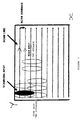
- In the invention, an increased scanning rate is accomplished, for instance, by scanning with a large laser spot (see figure 1), and overlapping the scan, such that each element in the field is scanned at least twice. The results of each adjacent pair of scans in the X direction are then compared in time synchrony for the purpose of maintaining the probability of detection by eliminating uncorrelated signals. Thus, each positive event is correlated between two or more scan lines, (depending on the size of the fluorescent object).
- As the laser spot moves along scan lines on the solid support (such as a filter membrane) the fluorescence light emitted (if any) is measured continously by one or more detectors (at various wavelengths). The analog signal coming out of the detectors is digitalized by taking its value at constant frequency intervals.
- Reading: a reading is the value of the signal at the time of measurement.
- Sample: a sample is defined as a reading of the signal from the detector which exceeds a given dynamic threshold.
- Feature: a set of adjacent samples on one scan line is called a feature.
- Line to line correlation: 2 samples are said to be correlated when they appear in time synchrony on two adjacent scan lines.
- Single feature: a feature which appears on only one scan line, ie which is not correlated, is called a single feature.
- Fluorescent spot : fluorescence emitted by any fluorescent particle when excited by a laser beam. These particles can be microorganisms or other elements such as dust.
- The particles can be autofluorescent or have been made fluorescent for the detection (for example, microorganisms).
- Event: an event is a set of at least two features which are correlated in time synchrony on adjacent scan lines.
- An event is the translation of a fluorescent spot in the measurement process.
- An event may subsequently be classified by the discriminator as either a positive event (ie an event being searched, such as a microorganism) or as a noise event (ie an event to be rejected as due to fluorescence generated for example by autofluorescent particles). A noise event, if included in the final count, would give false positives.
- Laser spot: light spot formed by a laser beam on a solid support.
- Interline or line spacing Y: distance between two scanning lines.
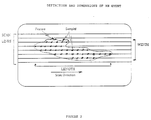
- Some of said definitions are illustrated in figure 2, in which samples are represented by ○ and in which the length of an event (set of correlated-features) corresponds to the number of accumulated count of samples from the start of the feature occuring the earliest in a scan-line in the scan direction, and the end of the feature which terminates the latest in a scan line, said counting taking as one sample all the correlated samples on different scan lines, and the width of an event is defined by the number of adjacent lines on which the same event appears.
- In one aspect of the present invention, a method for counting fluorescent microorganisms on a solid support (or specimen support) such as a filter membrane, is provided. Said method is characterized in that it comprises:
- scanning a solid support on which a sample potentially containing microorganisms has been deposited, the said sample having been subject to fluorescent staining, with an incident beam from a laser, forming a laser spot on the solid support, said laser spot being substantially greater than the microorganisms to be detected, said laser spot size being comprised between 4 and 14 µm, wherein the distance between two scanning lines is such that each element of the support is scanned at least twice, by partial overlapping of adjacent scanning paths and is preferably less than half the dimension of said laser spot size; and simultaneously:
- detecting the resultant fluorescent light at least at one wavelength, by selecting only detected signals exceeding a given threshold (=samples), for instance a dynamic threshold, wherein a set of adjacent samples on a scan-line represents a feature;
- establishing a set of correlated-features by a line-to-line correlation of individual features, by comparing features on each pair of adjacent lines in time-synchrony, counting the number of lines over which said set of correlated-features occur, each set of correlated-features forming an event, and eliminating any single uncorrelated-features;
correlation is considered as existing when one or more samples within the two features under comparison are detected in the same position on said pair of lines. The number of lines over which said set of correlated-features occur is counted, and thereafter used in size discrimination; - comparing said correlated-features on each pair of adjacent lines in time synchrony, at least at two different wavelengths λ₁ and λ₂, for selecting the correlated-features having an emission intensity ratio at said two wavelengths lower than a predetermined number, being specified that if the emission ratio at said wavelengths generated by any correlated-samples is greater than a predefined value, the complete event is eliminated;
- making a size discrimination of retained events and selecting those having a size corresponding to a microorganism;
- determining if for retained events after size discrimination, the events energy profile in three dimensions is within predetermined Gaussian shape criteria and rejecting events not within said predetermined Gaussian shape criteria. Such analysis is for instance performed by a software curve-fitting algorithm. All events within the criteria are accepted as microorganism for the final count; those outside the criteria are classified as noise (dust or other contaminants on said solid support);
- counting said remaining events to determine and to count exclusively the microorganisms present on said solid support.
- The expression "size-discrimination" means that only events having a given number of correlated-features and a given number of samples are retained towards the final counts. In such case, the instant process comprises evaluating the number of scan lines covered by one event (width) and the number of samples forming the length of the event; this latter number deriving from accumulated count of samples from the start of the feature occuring the earliest in a scan-line in the scan direction, and the end of the feature which terminates the latest in a scan line, counting as one any sample appearing at the same location on 2 or more adjacent lines. Events are eliminated if comprising such overall sample count length greater than a predetermined number A, and a number of scan-lines greater than a predetermined number B (refer to figure 2).
- More precisely, according to a preferred embodiment of said aspect of the invention, said size discrimination is carried out by:
- determining the length of each event by counting the number of samples, by starting with the sample appearing first on the scanning direction on whatever feature of said event occuring the earliest, continue to include the sample appearing last in the scan direction on whatever feature ends last, said counting taking as one sample all the correlated samples on different scan lines,
- determining the width of said event by counting the number of adjacent lines covered by the same event and
- eliminating events for which the number of said counted samples is greater than a predetermined number A, and/or the number of said adjacent scan-lines is greater than a predetermined number B.
- In another aspect of the present invention, the instant process is characterized in that it comprises:
- collecting microorganisms from a sample on a solid support, such as a filter membrane;
- labelling said microorganisms with a dye selected from the group constituted by vital dyes, viability markers, fluorescence substances carried by antibodies or nucleic probes, or generated by an enzyme linked probe system, capable, when excited, to produce an emission fluorescent at a wavelength λ₁;
- scanning said solid support with an incident beam from a laser, forming a laser spot on said solid support, said laser spot being substantially greater than the microorganisms to be detected, said laser spot size being comprised between 4 and 14 µm, wherein the distance between two scanning lines is such that each element of the support is scanned at least twice by partial overlapping of adjacent scanning paths and is preferably less than half the dimension of said laser spot size, and simultaneously:
- detecting the resultant fluorescent light at least at one wavelength, by selecting only detected signals exceeding a given threshold (=samples), wherein a set of adjacent samples on a scan-line represents a feature;
- establishing a set of correlated-features by a line-to-line correlation of individual features, by comparing features on each pair of adjacent lines in time synchrony, counting the number of lines over which said set of correlated-features occur, each set of correlated-features forming an event, and eliminating any single uncorrelated-features;
correlation is considered as existing when one or more samples within the two features under comparison are detected in the same position on said pair of lines. The number of lines over which said set of correlating-features occur is counted, and thereafter used in size discrimination; - comparing said correlated-features on each pair of adjacent lines in time synchrony, at least at two different wavelengths λ₁ and λ₂ for selecting the correlated-features having an emission intensity ratio at said two wavelengths lower than a predetermined number, being specified that if the emission ratio at said wavelengths generated by any correlated samples is greater than a predefined value, the complete event is eliminated;
- making a size discrimination of retained events and selecting those having a size corresponding to a microorganism;
- determining if for retained events after size discrimination, the events energy profile in three dimensions is within predetermined Gaussian shape criteria and rejecting events not within said predetermined Gaussian shape criteria. Such analysis is for instance performed by a software curve-fitting algorithm. All events within the criteria are accepted as microorganism for the final count; those outside the criteria are classified as noise (dust or other contaminants on said solid support);
- counting said remaining events to determine and to count exclusively the microorganisms present on said solid support.
- The expression "size-discrimination" has the same meaning as above.
- More precisely, according to a preferred embodiment of said aspect of the invention, said size discrimination is carried out by:
- determining the length of each event by counting the number of samples, by starting with the sample appearing first on the scanning direction on whatever feature of said event occuring the earliest, continue to include the sample appearing last in the scan direction on whatever feature ends last, said counting taking as one sample all the correlated samples on different scan lines,
- determining the width of said event by counting the number of adjacent lines covered by the same event and
- eliminating events for which the number of said counted samples is greater than a predetermined number A, and/or the number of said adjacent scan-lines is greater than a predetermined number B.
- As stated hereabove, the distance between two scanning lines (interline or line spacing y) is less than half the dimension of said laser spot size, leading to an overlap of the scanned surface.
- Preferably, the step of detecting the resulting fluorescent light is performed by measuring signals exceeding a dynamic threshold, by means of a digital signal processor (DSP).
- Said DSP allows to differentiate between wanted signals (corresponding to microorganisms) and some unwanted signals (electronic noise for instance).
- Such a process avoids, unexpectedly, both false negative and false positive results.
- The following Table I summarizes the potential causes for false negative or false positive results and the relevant steps of the instant process to eliminate the errors.
TABLE I Possible causes Relevant steps for correction False positive PMT noise Line to line correlation Background fluorescence of filter Gaussian curve Dynamic thresholding Autofluorescent dirt or particle having absorbed the dye Colour discrimination Size discrimination False negative Area not covered Overlapping and full filter scanning Bacteria signal not discriminated above background Background level thresholding Bacteria assigned as PMT noise or dirt Colour discrimination Line to line correlation Size discrimination - It must be highlighted that the present process handles only with fluorescent spots and identifies fluorescently-labelled bacteria by analysis of the label's fluorescent response to a scanning laser. The analysis technique makes use of fluorescence discrimination comprising:
- evaluation of the number of adjacent samples on a scan line (=feature),
- line to line correlation and
- number of correlated features in view to make a "size discrimination" as defined hereabove and to provide an accurate detection of microorganisms.
- Therefore, the instant analysis technique makes use of the size of the object to detect only in the following two ways:
- the fluorescent response on any single scan line must be large enough to exceed a predetermined noise threshold;
- a feature must be detected with a predetermined degree of overlap on at least two consecutives line scans.
- These requirements mean that the instant process differs markedly from imaging systems, which require significantly more information on the shape and size of a feature.
- These requirements drive the design of an imaging system towards small laser spot size, in order that the spot is smaller than the object being detected. The instant spot size can be large relative to the feature, and is currently of the order of 10 times the feature size. This gives major benefits in sampling speed, optical accuracy requirements, and processing power (data handling rate and memory requirements).
- Unexpectedly, the instant process provides:
- dynamic thresholding of signal level: the data processing system continuously monitors background noise level, and adjusts the threshold level which features must exceed to be regarded as significant. This allows the system to tolerate variation in the behaviour of the membrane (solid support), both from membrane to membrane, and over the area of a single membrane;
- line-to-line correlation of signals: in order to be assigned as microorganism, features must be present on at least two scan lines;
- use of a green fluorescence spectrum shape for feature discrimination (red/green signal level). A feature detected in the green channel must have a corresponding red channel signal small or nil, as predicted from the shape of the green fluorescent marker emission spectrum. A higher level of red channel response will cause the feature to be rejected;
- . signal discrimination: signals must be present for a predetermined number of scan points in order to be acceptable. Short signals are rejected as noise;
- correlated features comprising above a predetermined number of samples or above a predetermined number of lines (i.e., either along a given scan line, or across several line scans) are rejected.
- In another aspect of the present invention, an apparatus for detection and counting of microorganisms by fluorescence on a solid support is provided.
- Said apparatus is characterized in that it comprises:
- . a laser light source for emitting an incident light beam, cooperating with means for focusing said laser beam into a laser spot, the dimension of which on a solid support is substantially greater than the microorganisms to be detected and counted, said laser spot size being comprised between 4 and 14 µm;
- . scanning means for directing the light from said light source onto said solid support to spotwise irradiate the microorganisms to produce fluorescence spots, wherein the distance between two scanning lines is such that each element of the support is scanned at least twice, by partial overlapping of adjacent scanning paths and is preferably less than the dimension of said laser spot size;
- . means for detecting and photoelectrically converting said emitted fluorescence at least at two different wavelengths λ₁ and λ₂;
- . means for discriminating and eliminating non-bacterial fluorescence including a digital signal processor and a plurality of optic paths for selecting at least two emission fluorescence wavelengths;
- . signal processing means for establishing sets of correlated-features by a line-to-line correlation of individual features, by comparing features on each pair of adjacent lines in time synchrony, counting the number of lines over which said set of correlated-features occur, each set of correlated-features forming an event, and eliminating any single uncorrelated features, occuring only on one line; comparing said correlated-features on each pair of adjacent lines in time synchrony, at least at two different wavelengths λ₁ and λ₂, for selecting the correlated-features having an emission intensity ratio at said two wavelengths lower than a predetermined number, being specified that if the emission ratio at said wavelengths generated by any correlated features is greater than a predefined value, the complete event is eliminated; making a size discrimination of retained events and selecting the events having a size corresponding to a microorganism; determining if for retained events after size discrimination, the events energy profile in three dimensions is within predetermined Gaussian shape criteria and rejecting events not within said predetermined Gaussian shape criteria, and counting said remaining events to determine and to count exclusively the microorganisms present on said solid support.
- Said apparatus allows that the entire surface of the solid support is scanned.
- According to one aspect of said apparatus, said scanning means comprises a first oscillating mirror, the axis of oscillation of which is perpendicular to the axis of the light beam for scanning a line by the beam; and a second mirror, the axis of which is perpendicular to the axis of oscillation of the first mirror, said second mirror executing a scanning movement synchronized with the scanning movement of said first mirror.
- According to another aspect of the apparatus, said detecting means includes at least two photomultipliers as a means for the photoelectric conversion.
- According to another aspect of the apparatus, said laser spot has an elongated shape.
- According to another aspect of the apparatus, said solid support is a filter membrane.
- According to another aspect of the apparatus, said sample holder cooperates with cooling means, such as ones leading to Peltier effect.
- In addition, a thin layer of a material such as silicon may be sandwiched between said sample holder and said filter membrane.
- Said thin layer has, for instance, the following advantages: no autofluorescence, low light reflexion at the excitation wavelength and easy to clean.
- The following figures can be used to describe the means by which the invention was reduced to practice.
-
- . Figure 1: drawing of overlapping scan pattern showing beam shape, scan pattern, direction and relative dimensions.
- . Figure 2: definition and dimension of an event.
- . Figure 3: sketch of the apparatus showing the laser, optics, scanning mirrors, specimen support, specimen support holder, detectors, and a black box for post detection electronics.
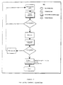
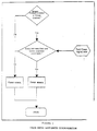
- . Figure 4: flow chart showing top level control algorithm.
- . Figure 5: flow chart showing feature detection.
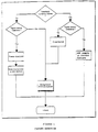
- . Figure 6: flow chart showing line correlation.
- . Figure 7: flow chart showing color ratio discrimination.
- . Figure 8: flow chart showing event size discrimination.
- . Figure 9: illustrates the principal scanning paramaters d, x, y.
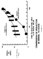
- . Figure 10: illustrates a comparison of reduction in signal to noise when the laser spot is circular (Case 1) or elongated (Case 2).
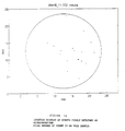
- . Figures 11 and 12: illustrate results obtained with the instant process in the detection of bacteria in water with a viability marker in one experiment.
- Figure 11 provides the setting of the instrument and the number of events detected and reported (19 in this experiment).
- Figure 12 shows the localisation of the microorganisms.
- Referring to figure 3, there is shown an apparatus according to the invention comprising scanning means 10, means for detecting the emitted fluorescence, including
dichroic filters 20,optical filters 21, photomultipliers (PMT) 30, a signal processing system 40-42, adigital signal processor 43, aninstrument PC 50, auser PC 60 and anautomated microscope 70. - The
scanning device 10 uses coherent light to scan asolid support 11, represented by a filter membrane, carried on amembrane holder 8. - In the preferred embodiment, the components of the
scanning device 10 include a 488 nm argon-ion water cooledlaser 12, scan mirrors 16, scanninglens 17 and abeam dump 18 which is a safety feature; said scanning means cooperates with means for focusing said laser beam into a laser spot comprising abeam expander 13 which controls the illuminating spot size to 4-14 µm, preferably 7 µm, and directs the illuminating spot onto said scan mirrors 16. - Said
beam expander 13 comprises two lenses, adapted (focal distance and distance between said two lenses), such as providing a laser spot on said solid support from 4 to 14 µm; for instance, to obtain a laser spot of 7 µm, focal distance of lens n°1 is 50 mm, focal distance of lens n°2 is 10 mm and the distance between the 2 lenses is 35,7 mm. - Said two scanning mirrors are used to scan the illuminating laser spot across the
solid support 11 on which is deposited the sample containing the microorganisms to be detected. The laser spot moves in the x direction at a speed for example of 1 meter per second. - Said scanning mirrors 16 (=scanner 16) allow, for instance, a line-to-line (y) spacing of 3 µm (distance between two scan lines).
- High optical accuracy is required from said scanning means to ensure accurate positioning of the laser spot (scanning lens 17).
- Using a laser spot size of 7 µm at a speed of 1 m/s, a 25 mm filter can be scanned in under 3 minutes.
- The solid support 11 (such as a filter membrane) on which is deposited the sample to be analyzed is placed on a removable sample holder, which is used to carry the specimen support from the laboratory, or from where ever the sample is collected, and to introduce it into the instant apparatus.
- The load drawer (not represented) is easily accessible to the user. The removable sample holder is designed to handle, for instance, a circular solid support and is deposited on the load drawer. The drawer is then pushed into the apparatus and the sample membrane carrying the microorganisms comes directly under the
scanner 16. The sample membrane holder is cooled to protect the stability of the labelled microorganism (for instance by Peltier effect). - Said sample loader cooperates with a mechanism to introduce the sample holder in the apparatus and to automatically bring it with precision at the right distance from the scanning lenses.
- The
scanner 16 passes the focused laser beam to thetarget 11, thereby inducing fluorescence from the microorganisms or any fluorescent material. - The thus fluorescent light emitted from the sample membrane passes through
dichroic filters 20 andoptical filters 21 to two photomultipliers (PMTs) 30. - Said
PMTs 30 detect fluorescence at two wavelengths referred to as the green and the red channels) (centred on 530 nm and 615 nm). - The PMT signals, together with time synchrony information from the
scanner 16, are passed to thesignal processing system 40. - This
system 40 comprisespre-amplifiers 41,signal sampling devices 42 and digitalsignal processing unit 43. - More precisely, each of said PMT signals is amplified by a
dedicated preamplifier 41. The amplified analogue signals are digitally sampled at 2 MHz, using 8-bit resolution (256 signal levels). Each PMT channel has a dedicated sampler. - The sampled PMT signals are passed to a Digital Signal Processor (DSP) 43.
- The signals are then analyzed and the resulting output information is passed through an
instrument PC 50, which controls the scanning device, acts as a host for theDSP system 43, stores data during solid support scanning and passes scan results to theuser PC 60. - Said
user PC system 60 is used to process and display the results of a scan, currently using Matlab® software, as the principal analytical tool. - The instant apparatus has the facility to allow, if necessary, direct observation of any object on the solid support, by driving an automated microscope from the
user PC 60. - Figures 4-8 sum up the different steps of the instant process in view to reject:
- background noise (dynamic threshold, figure 5),
- colour discrimination (figure 7),
- uncorrelated features (figure 6),
- size discrimination (figure 8).
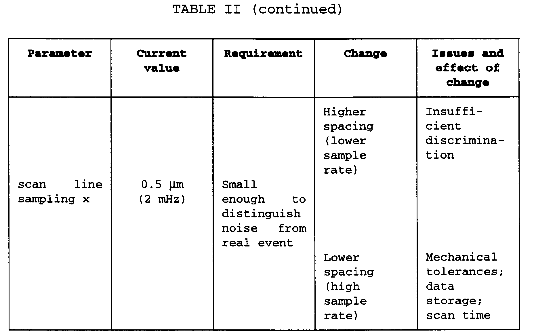
- The following scanning physical parameters: laser spot size (d), scan line sampling (x) and line spacing (y) influence the detection performance of the instant process, as illustrated in Figure 9. They are:
- . d: the scan laser spot dimension. The spot power distribution is Gaussian, and the spot dimension is usually defined as the dimension at which the laser intensity has fallen to (¹/e²) of the peak value (approximately 13%).
- . x: the distance between successive data samples on one scan line. This is controlled by the sampling rate, and the speed of the scanning mirrors.
- . y: the distance between successive scan lines. This is controlled by the step size used to move the scanning mirror.
- The effect of varying these parameters is summarised in Table II. It is clear that there is an optimum operating region for each parameter. The size of this region is determined by three principal constraining factors:
- . minimising the probability of obtaining false positive or false negative result;
- . practical engineering constraints (component tolerances, scanning mirror positional accuracy, etc);
- . processing and data analysis system costs (process speed, data storage memory).
- The role of these parameters is also shown in figures 1 and 10.
- The
target 11 is scanned as shown in figure 1. With reference to said figure 1, the scan time in terms of laser spot dimension and the SNR may be evaluated as follows: - total area scanned is X.Y
- scan velocity is v
- retrace time is negligible
- spot dimensions are ax and ay
- scan advance is Δy
- Thus, the time to scan is given by:

- However, all things are not equal and if the scan time is reduced by either the simple expedient of increasing the spot size or the velocity the signal to noise will be compromised.
- The signal is proportional to the intensity of illumination (watts/sq.cm.) and the time that each spot is illuminated. The noise is proportional to the square root of the illuminated area and inversely proportional to the scan velocity. Thus, considering that:
- the target microorganism is smaller than the illuminating spot;
- the total laser power is a constant (Io) and is spread over the illuminating spot;
- the scan may be overlapped as described above where n is the number of times each spot is scanned.
- The signal to noise can be expressed in terms of familiar quantities:

This demonstrates explicitly how the detection signal to noise is reduced as either the scan speed or laser spot dimension is increased. Even though this equation does not consider the recovery of signal to noise which will be gained by correlation of adjacent scan lines (see figure 1). - Figure 10 shows a comparison of the results of the two equations developed above, under two sets of conditions. In each case, it was assumed that an initial condition existed with a circular laser spot of dimension a. Under this condition, the SNR was 100% and the scan time was 100%.
- Condition 1: increase the laser spot dimension at constant velocity maintaining a circular spot and with no overlapping scan.

- Condition 2: elongate the spot by increasing the y dimension while decreasing the x dimension such that the spot area is constant and overlap so that each spot is scanned twice:

- An aliquot of water is diluted in a labelling buffer containing a fluorescent marker (fluorescein succimidyl ester). After 5 min at room temperature, the sample is filtered on a 0.22 µm pore size membrane and analysed using the present invention, with:
d=14 µm (laser diameter spot)
x=2 µm (scan sample spacing)
y=5 µm (scan line spacing). - The basis of the instant process is that the energy falling on a particle can be calculated at any point in the Gaussian beam profile; and all the following parameters can therefore be specified:
- . scan speed: v = 1 m/s
- . laser power (at the laser): L = 60 mwatts
- . optical efficiency: ζo = 0.66
- . collection efficiency ζ = 0.01
- . power on solid support: P = ζo.L
- . sample time t = 2 µs
- . fluorescent conversion: η = 2.10⁻³
- . background fluorescence conversion: ηb = 10⁻⁶
- . wavelength of light: λ = 0.53
- . quantum efficiency: q = 0.15
- . percentage in band: B = 0.89
- . PMT voltage: Z = 600
- . dynode constant κ = 0.75
- Aliquots of culture of different microorganisms are diluted in a saline buffered solution and filtered through an 0,2 µm pore size membrane; retained microorganisms are labelled by addition of 1 ml of labelling solution (viability marker)) followed by a 15 minutes incubation at room temperature.
- The resulting fluorescent labelled microorganims are detected and counted by carrying out the instant process with the parameters illustrated in the following table IV and which can vary according to the type of microorganisms tested.
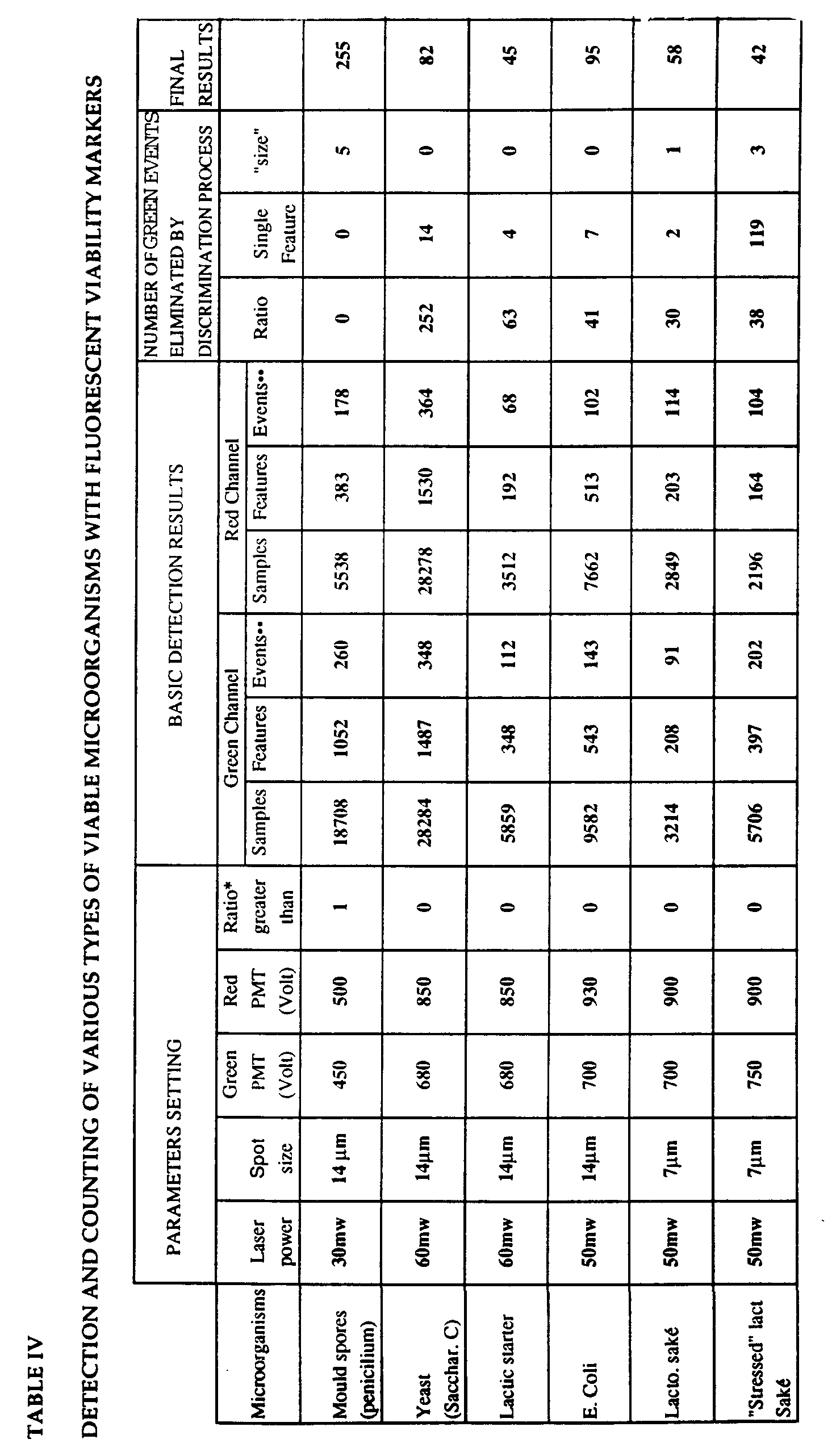
- It must be pointed out that in said Table IV, "*Ratio" means fluorescent intensity in the red channel divided by fluorescent intensity in the green channel and the columns marked "••" actually include the total of events as defined in the text and the number of uncorrelated features (also called single features).
- It is also to be noted that features and events may be found in the red channel only and vice versa and impact of discrimination by Gaussian after other criteria not shown on this Table.
- This Table IV shows that fluorescent particles other than relevant microorganisms are eliminated.



Claims (10)
- Method for detecting and counting fluorescent microorganisms on a solid support, characterized in that it comprises:- scanning a solid support on which a sample potentially containing microorganisms has been deposited, the said sample having been subject to fluorescent staining, with an incident beam from a laser, forming a laser spot on the solid support, said laser spot being substantially greater than the microorganisms to be detected, said laser spot size being comprised between 4 and 14 µm, wherein the distance between two scanning lines is such that each element of the support is scanned at least twice, by partial overlapping of adjacent scanning paths; and simultaneously:- detecting the resultant fluorescent light at least at one wavelength, by selecting only detected signals exceeding a given threshold (=samples), wherein a set of adjacent samples on a scan-line represents a feature;- establishing a set of correlated-features by a line-to-line correlation of individual features, by comparing features on each pair of adjacent lines in time-synchrony, counting the number of lines over which said set of correlated-features occur, each set of correlated-features forming an event, and eliminating any single uncorrelated-features;- comparing said correlated-features on each pair of adjacent lines in time synchrony, at least at two different wavelengths λ₁ and λ₂ for selecting the correlated-features having an emission intensity ratio at said two wavelengths lower than a predetermined number, being specified that if the emission ratio at said wavelengths generated by any correlated samples is greater than a predefined value, the complete event is eliminated;- making a size discrimination of retained events and selecting those having a size corresponding to a microorganism;- determining if for retained events after size discrimination, the events energy profile in three dimensions is within predetermined Gaussian shape criteria and rejecting events not within said predetermined Gaussian shape criteria; and- counting said remaining events to determine and to count exclusively the microorganisms present on said solid support.
- The method as in claim 1, wherein said size discrimination is carried out by:- determining the length of each event by counting the number of samples, by starting with the sample appearing first on the scanning direction on whatever feature of said event occuring the earliest, continue to include the sample appearing last in the scan direction on whatever feature ends last, said counting taking as one sample all the correlated samples on different scan lines,- determining the width of said event by counting the number of adjacent lines covered by the same event and- eliminating events for which the number of said counted samples is greater than a predetermined number A, and/or the number of said adjacent scan-lines is greater than a predetermined number B.
- Method for detecting and counting fluorescent microorganisms, which comprises:- collecting microorganisms from a sample on a solid support, such as a filter membrane;- labelling said microorganisms with a dye selected from the group constituted by vital dyes, viability markers, fluorescence substances carried by antibodies or nucleic probes, or generated by an enzyme linked probe system, capable, when excited, to produce an emission fluorescent at a wavelength λ₁;- scanning said solid support with an incident beam from a laser, forming a laser spot on said solid support, said laser spot being substantially greater than the microorganisms to be detected, said laser spot size being comprised between 4 and 14 µm, wherein the distance between two scanning lines is such that each element of the support is scanned at least twice by partial overlapping of adjacent scanning paths, and simultaneously:- detecting the resultant fluorescent light at least at one wavelength, by selecting only detected signals exceeding a given threshold (=samples), wherein a set of adjacent samples on a scan-line represents a feature;- establishing a set of correlated-features by a line-to-line correlation of individual features, by comparing features on each pair of adjacent lines in time synchrony, counting the number of lines over which said set of correlated-features occur, each set of correlated-features forming an event, and eliminating any single uncorrelated-features;- comparing said correlated-features on each pair of adjacent lines in time synchrony, at least at two different wavelengths λ₁ and λ₂, for selecting the correlated-features having an emission intensity ratio at said two wavelengths lower than a predetermined number, being specified that if the emission ratio at said wavelengths generated by any correlated features is greater than a predefined value, the complete event is eliminated;- making a size discrimination of said retained and selecting those having a size corresponding to a microorganism;- determining if for retained events after size discrimination, the events energy profile in three dimensions is within predetermined Gaussian shape criteria and rejecting events not within said predetermined Gaussian shape criteria; and- counting said remaining events to determine and to count exclusively the microorganisms present on said solid support.
- The method as in claim 3, wherein said size discrimination is carried out by- determining the length of each event by counting the number of samples, by starting with the sample appearing first on the scanning direction on whatever feature of said event occuring the earliest, continue to include the sample appearing last in the scan direction on whatever feature ends last, said counting taking as one sample all the correlated samples on different scan lines,- determining the width of said event by counting the number of adjacent lines covered by the same event and- eliminating events for which the number of said counted samples is greater than a predetermined number A, and/or the number of said adjacent scan-lines is greater than a predetermined number B.
- Apparatus for detecting and counting fluorescent microorganisms, characterized in that it comprises:. a laser light source (12) for emitting an incident light beam, cooperating with means for focusing (13) said laser beam into a laser spot, the dimension of which on a solid support (11) is substantially greater than the microorganisms to be detected and counted, said laser spot size being comprised between 4 and 14 µm;. scanning means (10) for directing the light from said light source onto said solid support to spotwise irradiate the microorganisms to produce fluorescence spots, wherein the distance between two scanning lines is such that each element of the support is scanned at least twice, by partial overlapping of adjacent scanning paths;. means for detecting (20, 21, 30) and photoelectrically converting said emitted fluorescence at least at two different wavelengths λ₁ and λ₂;. means for discriminating and eliminating non-bacterial fluorescence including a digital signal processor (43) and a plurality of optic paths for selecting at least two emission fluorescence wavelengths;. signal processing means (40, 41, 42) for establishing sets of correlated-features by a line-to-line correlation of individual features, by comparing features on each pair of adjacent lines in time synchrony, counting the number of lines over which said set of correlated-features occur, each set of correlated-features forming an event, and eliminating any single uncorrelated features, occuring only on one line; comparing said correlated-features on each pair of adjacent lines in time synchrony, at least at two different wavelengths λ₁ and λ₂, for selecting the correlated-features having an emission intensity ratio at said two wavelengths lower than a predetermined number, being specified that if the emission ratio at said wavelengths generated by any correlated features is greater than a predefined value, the complete event is eliminated; making a size discrimination of retained events and selecting the events having a size corresponding to a microorganism; determining if for retained events after size discrimination, the events energy profile in three dimensions is within predetermined Gaussian shape criteria and rejecting events not within said predetermined Gaussian shape criteria, and counting said remaining events to determine and to count exclusively the microorganisms present on said solid support.
- Apparatus as in claim 5, wherein said scanning means comprises a first oscillating mirror (16), the axis of oscillation of which is perpendicular to the axis of the light beam for scanning a line by the beam; and a second mirror, the axis of which is perpendicular to the axis of oscillation of the first mirror, said second mirror executing a scanning movement synchronized with the scanning movement of said first mirror.
- Apparatus as in claim 5, wherein said detecting means includes at least two photomultipliers (30) as a means for the photoelectric conversion.
- Apparatus as in claim 5, wherein said laser spot has an elongated shape.
- Apparatus as in claim 5, wherein said solid support is a filter membrane (11).
- Apparatus as in claim 5, wherein said solid support is placed on a sample holder (8) cooperating with cooling means and optionally a thin layer of silicon material sandwiched between said sample holder and said solid support.
Priority Applications (5)
| Application Number | Priority Date | Filing Date | Title |
|---|---|---|---|
| EP94402610A EP0713087B1 (en) | 1994-11-17 | 1994-11-17 | Apparatus and process for rapid and ultrasensitive detection and counting of microorganisms by fluorescence |
| DE69417900T DE69417900T2 (en) | 1994-11-17 | 1994-11-17 | Device and method for fast and highly sensitive detection and counting of microorganisms using fluorescence |
| US08/493,130 US5663057A (en) | 1994-11-17 | 1995-06-21 | Process for rapid and ultrasensitive detection and counting of microorganisms by fluorescence |
| JP7323740A JP3035698B2 (en) | 1994-11-17 | 1995-11-17 | Apparatus and method for fast and sensitive detection and counting of microorganisms by fluorescence |
| US08/870,294 US5891394A (en) | 1994-11-17 | 1997-06-06 | Apparatus for rapid and ultrasensitive detection and counting of microorganisms by fluorescence |
Applications Claiming Priority (1)
| Application Number | Priority Date | Filing Date | Title |
|---|---|---|---|
| EP94402610A EP0713087B1 (en) | 1994-11-17 | 1994-11-17 | Apparatus and process for rapid and ultrasensitive detection and counting of microorganisms by fluorescence |
Publications (2)
| Publication Number | Publication Date |
|---|---|
| EP0713087A1 true EP0713087A1 (en) | 1996-05-22 |
| EP0713087B1 EP0713087B1 (en) | 1999-04-14 |
Family
ID=8218061
Family Applications (1)
| Application Number | Title | Priority Date | Filing Date |
|---|---|---|---|
| EP94402610A Expired - Lifetime EP0713087B1 (en) | 1994-11-17 | 1994-11-17 | Apparatus and process for rapid and ultrasensitive detection and counting of microorganisms by fluorescence |
Country Status (4)
| Country | Link |
|---|---|
| US (2) | US5663057A (en) |
| EP (1) | EP0713087B1 (en) |
| JP (1) | JP3035698B2 (en) |
| DE (1) | DE69417900T2 (en) |
Cited By (17)
| Publication number | Priority date | Publication date | Assignee | Title |
|---|---|---|---|---|
| WO1999005513A1 (en) * | 1997-07-25 | 1999-02-04 | Nalco Chemical Company | Monitoring of film forming living deposits |
| WO2001063245A3 (en) * | 2000-02-25 | 2002-03-14 | The Technology Partnership Plc | Method and apparatus for high throughput cell - based assays for screening and diagnostics |
| WO2005031319A1 (en) * | 2003-10-02 | 2005-04-07 | Petra Perner | Methods for automatically identifying microorganisms collected on a carrier |
| EP1679364A1 (en) * | 2000-01-31 | 2006-07-12 | Matsushita Ecology Systems Co., Ltd. | Microorganism detecting kit, microorganism counting apparatus, and microorganism counting process |
| WO2006084552A1 (en) * | 2005-02-10 | 2006-08-17 | Henkel Kommanditgesellschaft Auf Aktien | Method for identifying germs |
| EP2241875A1 (en) * | 2009-04-14 | 2010-10-20 | Koninklijke Philips Electronics N.V. | Up-concentration of organic microobjects for microscopic imaging. |
| GB2476663A (en) * | 2009-12-31 | 2011-07-06 | Blood Analysis Ltd | Detection of microorganisms |
| WO2012159820A1 (en) * | 2011-05-20 | 2012-11-29 | Siemens Aktiengesellschaft | Automated ctc detection |
| WO2013166338A3 (en) * | 2012-05-02 | 2014-01-09 | Charles River Laboratories, Inc. | Cell capture system and use thereof |
| US8852875B2 (en) | 2007-04-20 | 2014-10-07 | The General Hospital Corporation | Methods for counting cells |
| US8993260B2 (en) | 2012-05-02 | 2015-03-31 | Charles River Laboratories, Inc. | Fluorescence-based viability staining method using a membrane permeable flourescent dye and membrane impermeable fluorescence quencher |
| US8991270B2 (en) | 2008-11-24 | 2015-03-31 | Koninklijke Philips N.V. | Method and apparatus for rapid filter analysis of fluid samples |
| CN104755931A (en) * | 2012-05-02 | 2015-07-01 | 查尔斯河实验室公司 | Method of detecting viable cells in a cell sample |
| EP2184346B1 (en) | 2001-09-06 | 2017-03-08 | Rapid Micro Biosystems, Inc. | Rapid detection of replicating cells |
| US9624463B2 (en) | 2013-11-04 | 2017-04-18 | Charles River Laboratories, Inc. | Filtration system and use thereof |
| US9958435B2 (en) | 2011-05-20 | 2018-05-01 | Siemens Healthcare Diagnostics Inc. | Arrangement and process for optical analysis and specific isolation of biological samples |
| WO2020070265A1 (en) | 2018-10-05 | 2020-04-09 | Redberry | Method and device for detecting at least one microorganism according to the labelling kinetics thereof, and detection support |
Families Citing this family (49)
| Publication number | Priority date | Publication date | Assignee | Title |
|---|---|---|---|---|
| US6122396A (en) * | 1996-12-16 | 2000-09-19 | Bio-Tech Imaging, Inc. | Method of and apparatus for automating detection of microorganisms |
| AU739824B2 (en) * | 1997-05-05 | 2001-10-18 | Chemometec A/S | A method and a system for determination of particles in a liquid sample |
| US6731100B1 (en) | 1997-05-05 | 2004-05-04 | Chemometec A/S | Method and a system for determination of somatic cells in milk |
| WO1999031488A1 (en) * | 1997-12-12 | 1999-06-24 | Chemunex S.A. | Digital flow cytometer |
| AU2884499A (en) * | 1998-03-02 | 1999-09-20 | Compucyte Corp. | Selective cell analysis |
| US5972641A (en) * | 1998-08-28 | 1999-10-26 | Colifast Systems Asa | Rapid coliform detection system |
| US6511819B2 (en) | 1998-08-28 | 2003-01-28 | Nye Colifast As | Rapid coliform detection system |
| GB9903555D0 (en) * | 1999-02-16 | 1999-04-07 | The Technology Partnership Plc | Chemical and biological assay method and apparatus |
| JP2000304689A (en) * | 1999-04-21 | 2000-11-02 | Hiroyuki Ogawa | Projection observing method, microorganism inspection method and projection detecting apparatus |
| WO2001046382A2 (en) * | 1999-12-21 | 2001-06-28 | Compucyte Corporation | Particle separation cassette and related methods |
| DE10100246A1 (en) * | 2001-01-05 | 2002-07-11 | Leica Microsystems | Confocal or double confocal microscope especially for imaging biomedical objects has a reference object integral with an object supporting carrier that can be used for rapid alignment and refocusing of the microscope |
| US6750039B1 (en) | 2001-03-21 | 2004-06-15 | Boston Probes, Inc. | Filtration apparatus and method for the separation of microscopic entities from a fluid |
| US6796710B2 (en) | 2001-06-08 | 2004-09-28 | Ethicon Endo-Surgery, Inc. | System and method of measuring and controlling temperature of optical fiber tip in a laser system |
| US6775315B1 (en) * | 2001-06-08 | 2004-08-10 | Scott Allen Nield | Apparatus and method of directing a laser beam to a thermally managed beam dump in a laser system |
| US6803208B2 (en) * | 2001-07-30 | 2004-10-12 | The United States Of America As Represented By The Secretary Of The Navy | Automated epifluorescence microscopy for detection of bacterial contamination in platelets |
| US20030027219A1 (en) * | 2001-07-31 | 2003-02-06 | Ilsley Diane D. | Methods for depositing small volumes of protein fluids onto the surface of a substrate |
| US7191103B2 (en) * | 2001-08-08 | 2007-03-13 | Hewlett-Packard Development Company, L.P. | Predominant color identification in digital images |
| US20030138906A1 (en) * | 2001-11-05 | 2003-07-24 | Ingun Tryland | Fluorescence test for measuring heterotrophic bacteria in water |
| US20030186252A1 (en) * | 2002-04-01 | 2003-10-02 | Ilsley Diane D. | Array based hybridization assays employing enzymatically generated labeled target nucleic acids and compositions for practicing the same |
| CA2487701C (en) * | 2003-11-21 | 2014-05-13 | Frederick David King | Automatic identification of suspended particles |
| US20070037135A1 (en) * | 2005-08-08 | 2007-02-15 | Barnes Russell H | System and method for the identification and quantification of a biological sample suspended in a liquid |
| CA2623408C (en) * | 2005-09-26 | 2014-04-01 | Rapid Micro Biosystems, Inc. | Cassette containing growth medium |
| US20080305514A1 (en) * | 2007-06-06 | 2008-12-11 | Alcon Research, Ltd. | Method for detecting microbes |
| EP2197350A2 (en) * | 2007-09-11 | 2010-06-23 | Baxter International Inc. | Infusion therapy sensor system |
| AU2009296526B2 (en) | 2008-09-24 | 2015-11-19 | First Light Diagnostics, Inc. | Method for detecting analytes |
| US20100112630A1 (en) * | 2008-11-03 | 2010-05-06 | Scott Martell Boyette | Methods for measuring microbiological content in aqueous media |
| US8481302B2 (en) * | 2008-11-03 | 2013-07-09 | General Electric Company | Total bacteria monitoring system |
| EP2194368B1 (en) | 2008-12-03 | 2019-07-17 | Grundfos Management A/S | Sensor system for detecting and specifying individual particles in a fluid |
| JP5837420B2 (en) | 2008-12-16 | 2015-12-24 | ビオメリュー・インコーポレイテッド | Method for characterizing microorganisms on solid or semi-solid media |
| US8358411B2 (en) * | 2008-12-18 | 2013-01-22 | Biovigilant Systems, Inc. | Integrated microbial collector |
| US9522396B2 (en) | 2010-12-29 | 2016-12-20 | S.D. Sight Diagnostics Ltd. | Apparatus and method for automatic detection of pathogens |
| DK3327110T3 (en) | 2011-11-07 | 2020-04-27 | Rapid Micro Biosystems Inc | Kassette til sterilitetstest |
| WO2013098821A1 (en) | 2011-12-29 | 2013-07-04 | Parasight Ltd. | Methods and systems for detecting a pathogen in a biological sample |
| EP2839021B1 (en) | 2012-04-16 | 2022-02-23 | Rapid Micro Biosystems, Inc. | Cell culturing device |
| IL227276A0 (en) | 2013-07-01 | 2014-03-06 | Parasight Ltd | A method and system for obtaining a monolayer of cells, for use specifically for diagnosis |
| EP3039477B1 (en) | 2013-08-26 | 2021-10-20 | S.D. Sight Diagnostics Ltd. | Digital microscopy systems, methods and computer program products |
| EP3859425B1 (en) | 2015-09-17 | 2024-04-17 | S.D. Sight Diagnostics Ltd. | Methods and apparatus for detecting an entity in a bodily sample |
| CA3018536A1 (en) | 2016-03-30 | 2017-10-05 | S.D. Sight Diagnostics Ltd | Distinguishing between blood sample components |
| EP4177593A1 (en) | 2016-05-11 | 2023-05-10 | S.D. Sight Diagnostics Ltd. | Sample carrier for optical measurements |
| EP3455626B1 (en) | 2016-05-11 | 2025-08-06 | S.D. Sight Diagnostics Ltd. | Performing optical measurements on a sample |
| EP3679154B1 (en) * | 2017-09-07 | 2026-03-18 | Eagle Analytical Services, Inc. | Method of preparing a sample for cytometry detection of viable biological contaminants |
| CN111788471B (en) | 2017-11-14 | 2023-12-12 | 思迪赛特诊断有限公司 | Sample carriers for optical measurements |
| CN119804399A (en) | 2018-04-19 | 2025-04-11 | 曙光诊断学公司 | Target Detection |
| AU2019353145B2 (en) | 2018-10-04 | 2025-12-04 | First Light Diagnostics, Inc. | Microbial analysis without cell purification |
| MX2022004703A (en) | 2019-10-22 | 2022-05-11 | S D Sight Diagnostics Ltd | ACCOUNTING FOR ERRORS IN OPTICAL MEASUREMENTS. |
| BR112022011233A2 (en) | 2019-12-12 | 2022-08-30 | S D Sight Diagnostics Ltd | DETECTION OF PLATELETS IN A BLOOD SAMPLE |
| CA3160702A1 (en) | 2019-12-12 | 2021-06-17 | S.D. Sight Diagnostics Ltd | Artificial generation of a color blood smear image |
| EP4073492A1 (en) | 2019-12-12 | 2022-10-19 | S.D. Sight Diagnostics Ltd. | Analyzing an analyte disposed within a medium |
| JP2025080006A (en) * | 2023-11-13 | 2025-05-23 | 浜松ホトニクス株式会社 | Laser measurement device and laser measurement method |
Citations (4)
| Publication number | Priority date | Publication date | Assignee | Title |
|---|---|---|---|---|
| US4180831A (en) * | 1975-05-23 | 1979-12-25 | Bausch & Lomb Incorporated | Image analysis data extraction |
| US4647531A (en) * | 1984-02-06 | 1987-03-03 | Ortho Diagnostic Systems, Inc. | Generalized cytometry instrument and methods of use |
| US5093866A (en) * | 1990-02-09 | 1992-03-03 | Hamilton Equine Associates Limited | Fluorescence and motility characterization system for cells, bacteria, and particles in fluids |
| US5103101A (en) * | 1991-03-04 | 1992-04-07 | Etec Systems, Inc. | Multiphase printing for E-beam lithography |
Family Cites Families (5)
| Publication number | Priority date | Publication date | Assignee | Title |
|---|---|---|---|---|
| US5246829A (en) * | 1984-10-04 | 1993-09-21 | Immunotech | Products for separation applicable to cells in the immunopurification field |
| US4745285A (en) * | 1986-08-21 | 1988-05-17 | Becton Dickinson And Company | Multi-color fluorescence analysis with single wavelength excitation |
| US4845653A (en) * | 1987-05-07 | 1989-07-04 | Becton, Dickinson And Company | Method of displaying multi-parameter data sets to aid in the analysis of data characteristics |
| US4845552A (en) * | 1987-08-20 | 1989-07-04 | Bruno Jaggi | Quantitative light microscope using a solid state detector in the primary image plane |
| JP3102938B2 (en) * | 1991-12-30 | 2000-10-23 | シスメックス株式会社 | Particle image analyzer |
-
1994
- 1994-11-17 EP EP94402610A patent/EP0713087B1/en not_active Expired - Lifetime
- 1994-11-17 DE DE69417900T patent/DE69417900T2/en not_active Expired - Lifetime
-
1995
- 1995-06-21 US US08/493,130 patent/US5663057A/en not_active Expired - Lifetime
- 1995-11-17 JP JP7323740A patent/JP3035698B2/en not_active Expired - Lifetime
-
1997
- 1997-06-06 US US08/870,294 patent/US5891394A/en not_active Expired - Lifetime
Patent Citations (4)
| Publication number | Priority date | Publication date | Assignee | Title |
|---|---|---|---|---|
| US4180831A (en) * | 1975-05-23 | 1979-12-25 | Bausch & Lomb Incorporated | Image analysis data extraction |
| US4647531A (en) * | 1984-02-06 | 1987-03-03 | Ortho Diagnostic Systems, Inc. | Generalized cytometry instrument and methods of use |
| US5093866A (en) * | 1990-02-09 | 1992-03-03 | Hamilton Equine Associates Limited | Fluorescence and motility characterization system for cells, bacteria, and particles in fluids |
| US5103101A (en) * | 1991-03-04 | 1992-04-07 | Etec Systems, Inc. | Multiphase printing for E-beam lithography |
Non-Patent Citations (1)
| Title |
|---|
| K.P. ROOS ET AL: "High-speed video imaging and digital analysis of microscopic features in contracting striated muscle cells", OPTICAL ENGINEERING, vol. 32, no. 2, BELLINGHAM US, pages 306 - 313, XP000338513, DOI: doi:10.1117/12.60739 * |
Cited By (36)
| Publication number | Priority date | Publication date | Assignee | Title |
|---|---|---|---|---|
| WO1999005513A1 (en) * | 1997-07-25 | 1999-02-04 | Nalco Chemical Company | Monitoring of film forming living deposits |
| EP1679364A1 (en) * | 2000-01-31 | 2006-07-12 | Matsushita Ecology Systems Co., Ltd. | Microorganism detecting kit, microorganism counting apparatus, and microorganism counting process |
| EP1256624B1 (en) * | 2000-01-31 | 2007-10-17 | Matsushita Ecology Systems Co., Ltd. | Kit for detecting microorganisms, apparatus for quantifying microorganisms and method for quantifying microorganisms |
| WO2001063245A3 (en) * | 2000-02-25 | 2002-03-14 | The Technology Partnership Plc | Method and apparatus for high throughput cell - based assays for screening and diagnostics |
| US11499176B2 (en) | 2001-09-06 | 2022-11-15 | Rapid Micro Biosystems, Inc. | Rapid detection of replicating cells |
| EP2184346B1 (en) | 2001-09-06 | 2017-03-08 | Rapid Micro Biosystems, Inc. | Rapid detection of replicating cells |
| WO2005031319A1 (en) * | 2003-10-02 | 2005-04-07 | Petra Perner | Methods for automatically identifying microorganisms collected on a carrier |
| WO2006084552A1 (en) * | 2005-02-10 | 2006-08-17 | Henkel Kommanditgesellschaft Auf Aktien | Method for identifying germs |
| US8852875B2 (en) | 2007-04-20 | 2014-10-07 | The General Hospital Corporation | Methods for counting cells |
| US8991270B2 (en) | 2008-11-24 | 2015-03-31 | Koninklijke Philips N.V. | Method and apparatus for rapid filter analysis of fluid samples |
| CN102395870A (en) * | 2009-04-14 | 2012-03-28 | 皇家飞利浦电子股份有限公司 | Up-concentration of organic microobjects for microscopic imaging |
| US9128016B2 (en) | 2009-04-14 | 2015-09-08 | Koninklijke Philips N.V. | Up-concentration of organic microobjects for microscopic imaging |
| CN102395870B (en) * | 2009-04-14 | 2013-12-25 | 皇家飞利浦电子股份有限公司 | Up-concentration of organic microobjects for microscopic imaging |
| WO2010119408A1 (en) * | 2009-04-14 | 2010-10-21 | Koninklijke Philips Electronics N.V. | Up-concentration of organic microobjects for microscopic imaging |
| EP2241875A1 (en) * | 2009-04-14 | 2010-10-20 | Koninklijke Philips Electronics N.V. | Up-concentration of organic microobjects for microscopic imaging. |
| GB2476663A (en) * | 2009-12-31 | 2011-07-06 | Blood Analysis Ltd | Detection of microorganisms |
| WO2012159820A1 (en) * | 2011-05-20 | 2012-11-29 | Siemens Aktiengesellschaft | Automated ctc detection |
| CN103620058B (en) * | 2011-05-20 | 2017-04-12 | 西门子公司 | Automated circulating tumor cell detection |
| US9958435B2 (en) | 2011-05-20 | 2018-05-01 | Siemens Healthcare Diagnostics Inc. | Arrangement and process for optical analysis and specific isolation of biological samples |
| CN103620058A (en) * | 2011-05-20 | 2014-03-05 | 西门子公司 | Automated circulating tumor cell detection |
| CN104685346A (en) * | 2012-05-02 | 2015-06-03 | 查尔斯河实验室公司 | Cell capture system and use thereof |
| US10976258B2 (en) | 2012-05-02 | 2021-04-13 | Charles River Laboratories, Inc. | Porous planar cell capture system and method of use |
| CN104755931A (en) * | 2012-05-02 | 2015-07-01 | 查尔斯河实验室公司 | Method of detecting viable cells in a cell sample |
| US8993259B2 (en) | 2012-05-02 | 2015-03-31 | Charles River Laboratories, Inc. | Method of viability staining with membrane permeable fluorescent dye and membrane impermeable fluorescence quencher |
| CN104755931B (en) * | 2012-05-02 | 2016-08-31 | 查尔斯河实验室公司 | For the method detecting the living cells in cell sample |
| US9709500B2 (en) | 2012-05-02 | 2017-07-18 | Charles River Laboratories, Inc. | Optical method for detecting viable microorganisms in a cell sample |
| US8993260B2 (en) | 2012-05-02 | 2015-03-31 | Charles River Laboratories, Inc. | Fluorescence-based viability staining method using a membrane permeable flourescent dye and membrane impermeable fluorescence quencher |
| US10324036B2 (en) | 2012-05-02 | 2019-06-18 | Charles River Laboratories, Inc. | Porous planar cell capture system |
| WO2013166338A3 (en) * | 2012-05-02 | 2014-01-09 | Charles River Laboratories, Inc. | Cell capture system and use thereof |
| US9624463B2 (en) | 2013-11-04 | 2017-04-18 | Charles River Laboratories, Inc. | Filtration system and use thereof |
| US10465228B2 (en) | 2013-11-04 | 2019-11-05 | Charles River Laboratories, Inc. | Filtration system and use thereof |
| FR3086951A1 (en) | 2018-10-05 | 2020-04-10 | Redberry | METHOD AND DEVICE FOR DETECTING AT LEAST ONE MICROORGANISM ACCORDING TO ITS MARKING KINETICS, AND DETECTION MEDIUM |
| WO2020070265A1 (en) | 2018-10-05 | 2020-04-09 | Redberry | Method and device for detecting at least one microorganism according to the labelling kinetics thereof, and detection support |
| CN112823211A (en) * | 2018-10-05 | 2021-05-18 | 红莓 | Method and device for detecting at least one microorganism according to staining kinetics and detection support |
| EP3861125A1 (en) * | 2018-10-05 | 2021-08-11 | Redberry | Method and device for detecting at least one microorganism according to the labelling kinetics thereof, and detection support |
| US12180532B2 (en) | 2018-10-05 | 2024-12-31 | Redberry | Method and device for detecting at least one microorganism according to the staining kinetics thereof, and detection support |
Also Published As
| Publication number | Publication date |
|---|---|
| JP3035698B2 (en) | 2000-04-24 |
| DE69417900D1 (en) | 1999-05-20 |
| US5663057A (en) | 1997-09-02 |
| JPH08292145A (en) | 1996-11-05 |
| US5891394A (en) | 1999-04-06 |
| EP0713087B1 (en) | 1999-04-14 |
| DE69417900T2 (en) | 1999-11-11 |
Similar Documents
| Publication | Publication Date | Title |
|---|---|---|
| EP0713087B1 (en) | Apparatus and process for rapid and ultrasensitive detection and counting of microorganisms by fluorescence | |
| EP0713086B1 (en) | Apparatus and process for the detection and counting of rarely occurring mammalian cells | |
| JP3290786B2 (en) | Particle analyzer | |
| US5480804A (en) | Method of and apparatus for detecting microorganisms | |
| US4979824A (en) | High sensitivity fluorescent single particle and single molecule detection apparatus and method | |
| JP2527540B2 (en) | Device for fluorescence signal analysis and image display | |
| CA2026617C (en) | Method and apparatus for measuring multiple optical properties of biological specimens | |
| JP2648376B2 (en) | Apparatus and method for detecting and counting microorganisms | |
| EP0681178B1 (en) | Apparatus and method for cytometry using a capillary of defined volume | |
| US6084991A (en) | CCD imager for confocal scanning microscopy | |
| EP0440342A2 (en) | Laser excited confocol microscope fluorescence scanner and method | |
| JP3102938B2 (en) | Particle image analyzer | |
| US20070196815A1 (en) | Positive Selection Procedure for Optically Directed Selection of Cells | |
| EP0592624A1 (en) | Diagnostic microbiological testing apparatus and method | |
| CN102216954A (en) | Method and device for analyzing particles in a liquid sample | |
| EP0501006A2 (en) | Flow imaging cytometer | |
| US20110017915A1 (en) | Drift scanner for rare cell detection | |
| US6674058B1 (en) | Apparatus and method for focusing a laser scanning cytometer | |
| CA2487701C (en) | Automatic identification of suspended particles | |
| CA2454294A1 (en) | Microbe inspection equipment and method | |
| Hilton | Laser induced fluorescence imaging of bacteria | |
| CN212410398U (en) | A static cell analysis device | |
| JP2007060945A (en) | Microbe counting device | |
| JPH01147513A (en) | Foreign matter analysis device | |
| JPS63243855A (en) | Charged particle analyzer |
Legal Events
| Date | Code | Title | Description |
|---|---|---|---|
| PUAI | Public reference made under article 153(3) epc to a published international application that has entered the european phase |
Free format text: ORIGINAL CODE: 0009012 |
|
| AK | Designated contracting states |
Kind code of ref document: A1 Designated state(s): DE FR GB IT |
|
| AX | Request for extension of the european patent |
Free format text: LT;SI |
|
| RAX | Requested extension states of the european patent have changed |
Free format text: LT;SI |
|
| 17P | Request for examination filed |
Effective date: 19960930 |
|
| 17Q | First examination report despatched |
Effective date: 19970818 |
|
| GRAG | Despatch of communication of intention to grant |
Free format text: ORIGINAL CODE: EPIDOS AGRA |
|
| GRAG | Despatch of communication of intention to grant |
Free format text: ORIGINAL CODE: EPIDOS AGRA |
|
| GRAH | Despatch of communication of intention to grant a patent |
Free format text: ORIGINAL CODE: EPIDOS IGRA |
|
| GRAH | Despatch of communication of intention to grant a patent |
Free format text: ORIGINAL CODE: EPIDOS IGRA |
|
| GRAA | (expected) grant |
Free format text: ORIGINAL CODE: 0009210 |
|
| AK | Designated contracting states |
Kind code of ref document: B1 Designated state(s): DE FR GB IT |
|
| REF | Corresponds to: |
Ref document number: 69417900 Country of ref document: DE Date of ref document: 19990520 |
|
| ET | Fr: translation filed | ||
| PLBE | No opposition filed within time limit |
Free format text: ORIGINAL CODE: 0009261 |
|
| STAA | Information on the status of an ep patent application or granted ep patent |
Free format text: STATUS: NO OPPOSITION FILED WITHIN TIME LIMIT |
|
| 26N | No opposition filed | ||
| REG | Reference to a national code |
Ref country code: GB Ref legal event code: IF02 |
|
| REG | Reference to a national code |
Ref country code: FR Ref legal event code: CD |
|
| PGFP | Annual fee paid to national office [announced via postgrant information from national office to epo] |
Ref country code: GB Payment date: 20131128 Year of fee payment: 20 Ref country code: DE Payment date: 20131121 Year of fee payment: 20 Ref country code: FR Payment date: 20130927 Year of fee payment: 20 |
|
| PGFP | Annual fee paid to national office [announced via postgrant information from national office to epo] |
Ref country code: IT Payment date: 20131105 Year of fee payment: 20 |
|
| REG | Reference to a national code |
Ref country code: DE Ref legal event code: R071 Ref document number: 69417900 Country of ref document: DE |
|
| REG | Reference to a national code |
Ref country code: GB Ref legal event code: PE20 Expiry date: 20141116 |
|
| PG25 | Lapsed in a contracting state [announced via postgrant information from national office to epo] |
Ref country code: GB Free format text: LAPSE BECAUSE OF EXPIRATION OF PROTECTION Effective date: 20141116 |