EP0713116A1 - Anamorphotisches System und Wärmebildgerät mit einem derartigen System - Google Patents
Anamorphotisches System und Wärmebildgerät mit einem derartigen System Download PDFInfo
- Publication number
- EP0713116A1 EP0713116A1 EP95402542A EP95402542A EP0713116A1 EP 0713116 A1 EP0713116 A1 EP 0713116A1 EP 95402542 A EP95402542 A EP 95402542A EP 95402542 A EP95402542 A EP 95402542A EP 0713116 A1 EP0713116 A1 EP 0713116A1
- Authority
- EP
- European Patent Office
- Prior art keywords
- plane
- optical
- prism
- ratio
- anamorphosis
- Prior art date
- Legal status (The legal status is an assumption and is not a legal conclusion. Google has not performed a legal analysis and makes no representation as to the accuracy of the status listed.)
- Withdrawn
Links
- 230000004075 alteration Effects 0.000 claims abstract description 8
- 230000003287 optical effect Effects 0.000 claims description 66
- 210000001747 pupil Anatomy 0.000 claims description 27
- 239000000463 material Substances 0.000 claims description 16
- 238000001514 detection method Methods 0.000 claims description 13
- 230000003595 spectral effect Effects 0.000 claims description 12
- 238000003331 infrared imaging Methods 0.000 claims description 10
- 230000001179 pupillary effect Effects 0.000 claims description 10
- 230000021615 conjugation Effects 0.000 claims description 7
- 238000003384 imaging method Methods 0.000 claims description 7
- 210000003128 head Anatomy 0.000 claims description 5
- 230000015572 biosynthetic process Effects 0.000 claims description 4
- 239000000470 constituent Substances 0.000 claims description 2
- 230000001902 propagating effect Effects 0.000 claims description 2
- 238000011084 recovery Methods 0.000 claims 1
- 230000035945 sensitivity Effects 0.000 claims 1
- 230000007547 defect Effects 0.000 description 6
- XUIMIQQOPSSXEZ-UHFFFAOYSA-N Silicon Chemical compound [Si] XUIMIQQOPSSXEZ-UHFFFAOYSA-N 0.000 description 5
- 201000009310 astigmatism Diseases 0.000 description 5
- 229910052710 silicon Inorganic materials 0.000 description 5
- 239000010703 silicon Substances 0.000 description 5
- 230000006978 adaptation Effects 0.000 description 4
- 230000005540 biological transmission Effects 0.000 description 4
- 230000004907 flux Effects 0.000 description 4
- 230000014509 gene expression Effects 0.000 description 4
- 229910052732 germanium Inorganic materials 0.000 description 3
- GNPVGFCGXDBREM-UHFFFAOYSA-N germanium atom Chemical compound [Ge] GNPVGFCGXDBREM-UHFFFAOYSA-N 0.000 description 3
- 230000010354 integration Effects 0.000 description 3
- 238000012545 processing Methods 0.000 description 3
- 230000002745 absorbent Effects 0.000 description 2
- 239000002250 absorbent Substances 0.000 description 2
- 239000003990 capacitor Substances 0.000 description 2
- 230000003111 delayed effect Effects 0.000 description 2
- 230000000694 effects Effects 0.000 description 2
- 210000000887 face Anatomy 0.000 description 2
- 230000001681 protective effect Effects 0.000 description 2
- 238000004611 spectroscopical analysis Methods 0.000 description 2
- 238000013519 translation Methods 0.000 description 2
- 230000009471 action Effects 0.000 description 1
- 239000002131 composite material Substances 0.000 description 1
- 239000004020 conductor Substances 0.000 description 1
- 238000007796 conventional method Methods 0.000 description 1
- 238000001816 cooling Methods 0.000 description 1
- 230000000593 degrading effect Effects 0.000 description 1
- 238000000151 deposition Methods 0.000 description 1
- 238000013461 design Methods 0.000 description 1
- 238000011161 development Methods 0.000 description 1
- 238000010586 diagram Methods 0.000 description 1
- 238000006073 displacement reaction Methods 0.000 description 1
- 235000021183 entrée Nutrition 0.000 description 1
- WPYVAWXEWQSOGY-UHFFFAOYSA-N indium antimonide Chemical compound [Sb]#[In] WPYVAWXEWQSOGY-UHFFFAOYSA-N 0.000 description 1
- 238000000034 method Methods 0.000 description 1
- 230000003071 parasitic effect Effects 0.000 description 1
- 230000010287 polarization Effects 0.000 description 1
- 230000008569 process Effects 0.000 description 1
- 230000005855 radiation Effects 0.000 description 1
- 230000009467 reduction Effects 0.000 description 1
- 238000005070 sampling Methods 0.000 description 1
Images


Classifications
-
- G—PHYSICS
- G02—OPTICS
- G02B—OPTICAL ELEMENTS, SYSTEMS OR APPARATUS
- G02B25/00—Eyepieces; Magnifying glasses
- G02B25/001—Eyepieces
-
- G—PHYSICS
- G02—OPTICS
- G02B—OPTICAL ELEMENTS, SYSTEMS OR APPARATUS
- G02B13/00—Optical objectives specially designed for the purposes specified below
- G02B13/08—Anamorphotic objectives
- G02B13/10—Anamorphotic objectives involving prisms
-
- G—PHYSICS
- G02—OPTICS
- G02B—OPTICAL ELEMENTS, SYSTEMS OR APPARATUS
- G02B13/00—Optical objectives specially designed for the purposes specified below
- G02B13/14—Optical objectives specially designed for the purposes specified below for use with infrared or ultraviolet radiation
Definitions
- the invention relates to the field of imaging, in particular infrared imaging in which the useful spectral bands are those which promote atmospheric transmission.
- the bands 3 to 5 ⁇ m and 8 to 12 ⁇ m are used, for which there are photosensitive materials well suited for their detection, for example indium antimony (lnSb) or a mercury-cadmium-tellium composite material. (Hg-Cd-Te).
- the invention applies in particular, but not exclusively, to infrared imaging devices with unidirectional, horizontal or vertical scanning, comprising a scene scanning mirror defining an axis of sight for a detector bar of main axis orthogonal to the scanning direction.
- Infrared imaging detectors are in the form of a mosaic of spaced elementary cells, made of photosensitive material and arranged to form a strip.
- TDI type technology initials of the Anglo-Saxon expression “Time and Delay Integration” which means Temporarily Delayed Integration
- Congestion reasons can then lead to using a large spacing between the cells in the direction of the processing circuits, greater than what is desired for optical reasons.
- TDI technology uses a detector mosaic composed of a large number of rows of a few cells arranged in the scanning direction to form a detector strip extending in an orthogonal direction.
- the rows can be aligned, staggered or in an architecture combining these two modes.
- Each cell of the same row then successively receives, during scanning, the same light flux coming from the same portion of the scene.
- the output signals of the cells of the same row are delayed in synchronism with the scanning speed to be accumulated in a summing circuit.
- TDI technology is performed more precisely using charge storage capacitors built into the back of the detector plane.
- the conductors connecting the cells to the capacitors occupy a non-negligible space between the cells.
- a solution is to make cells of rectangular shape whose length and width extend in two main directions, respectively the scanning direction and a direction orthogonal thereto. Under these conditions, the elementary field of view of each of these cells has an elementary field of view ⁇ different according to the two main orthogonal directions.
- This problem has been solved in the field of visible radiation, in particular by Brewster, by developing anamorphic means, for example prisms or cylindrical lenses, to modify the fields contained in a meridian anamorphic plane, without modifying the image in the orthogonal plane. It is possible to quantify the spread obtained by the value of a so-called anamorphosis ratio, equal to the magnification ratio of the anamorphic element in the two main directions.
- the invention aims to overcome these defects by using an anamorphic eyepiece without dioptric aberration, without mechanical complication, while retaining good optical transmission.
- the invention proposes an anamorphic eyepiece with two prisms whose functions are rigorously decoupled: the first prism is dedicated entirely to anamorphosis, and the second prism, used at the minimum of deviation in order to induce no effect anamorphic, is calculated so as to compensate for the dioptric defects induced by the first prism, the two prisms having the same refractive index and being used in parallel beams.
- the subject of the invention is an anamorphic eyepiece comprising a first and a second prism made of a material of known index, arranged head to tail along the same plane of main section, characterized in that, the first and the second prisms being successively crossed by a parallel light beam radiating in a given spectral band and propagating along an axis located in the plane of main section, only the first prism causes an anamorphosis of the beam in a predetermined ratio and has an angle at the apex of which the value is adjusted as a function of that of the desired anamorphosis ratio and of the index of the constituent material in the given spectral band, in that the second prism is oriented relative to the beam emerging from the first prism to be used at its minimum deviation so as not to introduce any anamorphosis, and in that the second prism has an angle at the apex whose value e st adjusted according to those of the anamorphosis ratio and the index to obtain a compensation of axi
- the invention also relates to an infrared imaging device comprising in particular a scanning mirror and an optical transport combination, for forming over time a scene image on an infrared detector mosaic arranged in a cryostat.
- the anamorphic eyepiece is coupled to the optical transport combination to be integrated into the infrared imaging device.
- the transport suit then includes a cylindrical lens in order to obtain a single exit pupil for the entire optical system composed of the eyepiece and the transport suit.
- the transport combination is calculated so that this exit pupil coincides with the actual opening of the cryostat defining the diaphragm, called the cold diaphragm, of the detector.
- this opening is conventionally shaped so that the cold diaphragm allows only the useful flow coming from the scene to pass, by stopping all the parasitic flows emitted by elements of internal structure. Under these conditions, the detector not only receives only the useful flow, but then receives all the useful flow.
- the transport combination advantageously consists of two groups of lenses of positive power, which gives a real and accessible intermediate image, calculated to bring the entrance pupil of the optical system to the axis of rotation of the scanning mirror of the device.
- infrared imagery for fields located in a plane perpendicular to the anamorphic plane.
- a cylindrical lens placed in the vicinity of the intermediate image makes it possible to adjust the pupillary conjugations to keep the entrance pupil always on the scanning mirror.
- the use of a cylindrical lens which acts as a field group finally makes it possible to have a single pupil at the input, whatever the orientations of the fields, located on the scanning mirror. This makes it possible to reduce the dimensions of the scanning mirror and to precisely couple the optical system to a frontal afocal group conventionally arranged at the input of the imaging devices.
- the cylindrical lens does not participate, under the conditions of implementation mentioned, in the power of the optical system.
- the thermal defocusing of this system can then be corrected by moving a single group of lenses.
- the associated mechanics for achieving such a translation is simplified.
- optical system of such an infrared imaging device forms on the detector mosaic an undegraded image due to the fact that the optical transmission is effected by a minimum of elements and the absence of drifts of aiming axes coinciding with the optical axis of this system.
- FIG. 1 A schematic example of anamorphic eyepiece according to the invention is illustrated in FIG. 1 in section on a plane of main section of the prisms shown.
- the anamorphic eyepiece has two prisms with main sections merged with the plane of the figure and arranged head to tail, a first prism P1 with an angle at the apex A1 and main faces f e and f s , and a second prism P2 d ' angle at the vertex A2 and main faces f ' e and f' s .
- the two prisms, formed from the same material have the same refractive index n.
- An incident parallel light beam F i strikes the entry face f e of the first prism P1 and emerges from the exit face f s of this prism in the form of a parallel beam F i .
- the beam F i forms an angle i1 with the exit normal N1 perpendicular to the face f s .
- the incident beam F i is shown perpendicular to the input face f e .
- the beam F i emerging from the prism P1 strikes the input face f ' e of the second prism P2 at an angle i2, measured with respect to the normal N2 at the input face, then emerges from this prism P2 by the face of exit f ' s . at an angle i'2, measured with respect to the normal N'2 at the face f ' s .
- the first prism is anamorphic.
- the anamorphosis is created in the main section plane by the anisotropic deflection operated by the prism on the incident beam.
- the section of the beam is no longer circular but is narrowed in the plane of main section, which results in the figure by a narrowing of the beam F i after crossing the prism.
- the emerging beam when the beam F i scans an observation field, the emerging beam describes a wider field in the plane of main section due to the principle of the conservation of the quantity of light flux transported. According to this principle, the product "swept field” ⁇ "section of pupil crossed” is constant for a given incident beam.
- the anamorphosis can be defined, for the same field scanned in the plane of main section and in an orthogonal plane as the ratio m between the magnifications used in these two planes.
- the second prism P2 is on the other hand oriented relative to the emerging beam of the first prism P1 so as to be used at its minimum deflection. Under these conditions, the angles of incidence and emergence of the beam F i are identical in the plane of main section for which the angle of incidence i2 is therefore equal to the angle of emergence i'2. Thus, the prism P2 does not introduce any additional anamorphosis.
- the prism P2 is adjusted to compensate for all of the dioptric aberrations introduced into the first prism P1.
- Dioptric aberrations can be translated, directly or by parametric equivalence as explained below, by a variation of index. If the angle of the second prism, A2, is adjusted appropriately, the prisms, used under the same conditions - same material, same spectral band, same main section - cause identical diotic aberrations, which results in the same variation d 'index.
- the variation in index ⁇ n is caused by dioptric defects which originate from the chromaticism, the axial drift in temperature, and the distortion which causes a curvature of the lines perpendicular to the plane of main section.
- FIG. 2 represents in a side view a prism P of angle at the apex A defined in a plane of main section of the prism.
- a portion of line L, formed in a plane ⁇ perpendicular to the plane of main section of the prism for polarization optics (not shown), has an image in the plane ⁇ formed by passing through the prism P which has a certain curvature.
- An incident ray R i coming from a point of the line L and which forms an angle ⁇ with the normal N of the plane of principal section in the plane ⁇ , has for image a ray emerging R ' i through the prism P.
- an anamorphic eyepiece consists of two silicon prisms with an index equal to 3.4254 at the average wavelength of the spectral band 3-5 ⁇ m; this eyepiece performs an anamorphosis with a ratio m equal to 2 when the apex angles A1 and A2 of the first and second prism are respectively 14.807 ° and 22.600 °, and when the incident beam, taken perpendicular to the entry face of the first prism, comes out of this prism and enters the second prism (used at its minimum deviation) at angles i1 and i2 respectively equal to 61.093 ° and 42.160 °.
- the calculation shows that its variations, caused for example by a temperature difference ⁇ 40 ° C or along a horizontal observation field of ⁇ 1.25 ° in the plane of main section, does not exceed 0.3%, which again remains negligible.
- An anamorphic device such as that which has just been described can be integrated into an infrared imaging device, for example an observation camera in the infrared spectral band 3-5 ⁇ m.
- the anamorphic eyepiece is coupled to an optical transport combination which forms a final image on a detector mosaic and which is adapted to the eyepiece to present a single exit pupil in a predetermined plane.
- the exit pupil is then positioned in the same plane.
- Figure 3 shows schematically a sectional view of an infrared imaging device according to the invention.
- This exemplary embodiment is that of an infrared camera with horizontal scanning.
- Figure 3 illustrates, in horizontal section, the main elements related to the invention.
- a frontal afocal group 10 which makes it possible to properly adapt the fields scanned by the camera to operational needs , an oscillating scanning mirror 20 of vertical axis V'V perpendicular to the plane of the figure which ensures the horizontal exploration of the image of a scene observed by the camera in a given field of view, an anamorphic eyepiece 30 coupled to a combination of image transport 40 to form the optical system of the camera, and a cryostat 50.
- This cryostat defines a diaphragm 51, hereinafter called the cold screen, and houses a detection mosaic 52 forming a strip oriented in a direction direction perpendicular to the scanning direction; the mosaic is associated with an electronic processing circuit signal (not shown).
- the mosaic is cooled by a cold finger 53 maintained at about 77 ° K by a cooling machine (not shown).
- the optical transport combination 40 is intended to transport the image of the instantaneous scene portion formed by the horizontal scanning mirror 20 to the detector mosaic 52.
- This combination can, on the other hand, be calculated so as to define an entrance pupil for the incident flow treatment unit 20-50, which substantially coincides with the axis of rotation V'V of the mirror 20. Under these conditions, the dimensions of this mirror can be reduced to minimum values and are therefore optimized. Such an optical combination calculation does not raise any particular problem.
- the frontal afocal group 10 then operates directly for the instantaneous opening of the optical processing assembly: no pupil shift induced by the scanning occurs.
- the anamorphic eyepiece 30 is of the type described above. It consists of the two prisms P1 and P2, arranged head to tail along the same plane of main section coinciding with the horizontal plane.
- Such an anamorphic, achromatic device corrected for thermal drifts and practically devoid of distortions, makes it possible to reduce the elementary field of view of each detection cell in the horizontal plane coinciding with the main section plane of the prisms.
- the horizontal field reduction is then caused by the upper value of the focal length of the optical system in the main section plane coinciding with the horizontal scanning plane.
- the vertical and horizontal elementary fields are similar if the anamorphosis ratio is chosen equal to the dimensional ratio between the width and the height of the cells.
- the optical transport combination comprises a cylindrical field lens 41 to compensate for pupillary astigmatism at the input of this combination.
- This pupillary astigmatism is caused by the anamorphic device 30 which induces the formation of input pupils offset in the plane of main section and in the orthogonal vertical plane as illustrated below.
- the cylindrical lens 41 has a vertical axis in the example described, and has plano-convex faces calculated so that the optical power in the horizontal plane compensates for the pupillary offset.
- the calculation of the transport combination can be adapted so that the entrance pupil, image of the aperture diaphragm, is on the axis of rotation of the scanning mirror and that it does not depend on position of the field orientation.
- the cold screen 51 constitutes the aperture diaphragm of the camera.
- the entrance pupils are conjugated by the optics composing the eyepiece and the prisms of this aperture diaphragm.
- Such a screen is conventionally adapted so as to let through only the useful beams, by interrupting the spurious signals emitted or returned by the structural elements internal to the camera.
- the detector mosaic receives not only only the useful flux coming from of the observed scene, but also all the useful flow.
- the cold diaphragm can be elliptical in shape, the dimensional relationships between the large and the minor axis being worth the ratio of anamorphosis.
- the lens 41 does not contribute to the optical power produced by the transport combination 40, since it is calculated to cause only a pupil translation in the main section plane of the anamorphic system 30.
- the thermal defocuses of this combination are identical in all the planes, so that the conventional method of compensation by displacement of a single group of lenses of the combination, remains applicable.
- a protective filter of the saturable absorbent type in order to obtain protection against laser threat.
- a filter is all the more effective as the optical density is high.
- the scanning mirror 20 and the anamorphic eyepiece 30 operating in parallel beams a real image can be formed in the optical transport combination.
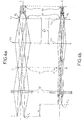
- FIGS. 4a and 4b more precisely represent the optical path of an incident beam coming from an observed scene, after crossing the prismatic anamorphoser, respectively in a vertical field of view equal to 2 ⁇ 10.2 ° according to the plane vertical, and 2 ⁇ 2.54 ° at the input of the optical transport, or 2 ⁇ 1.27 ° at the input of the eyepiece, along the horizontal plane covered by the horizontal scanning mirror.
- FIGS. 4a and 4b show more particularly the pupillary conjugations produced by the combination of optical transport, respectively in the vertical plane coinciding with the vertical field of view, and in the horizontal plane coinciding with the horizontal field of view.
- the optical transport combination is calculated so that the image of the entrance pupil formed on the scanning mirror is projected onto the detector 52, whether in the vertical or horizontal plane.
- the anamorphic eyepiece causes pupillary astigmatism which is shown in FIGS. 4a and 4b by an offset ⁇ between the image of the entrance pupil of the optical system obtained by the anamorphic eyepiece. , called P v in the vertical plane and P h in the horizontal plane.
- the optical combination 40 is composed of two optical groups G1 and G2 which produce a pupillary conjugation between the pupil (not shown) located on the scanning mirror 20, and the exit pupil P s of the optical system. The combination is calculated so that this exit pupil coincides with the opening of the diaphragm of the cold diaphragm 51, whatever the position of the entry pupils P v and P h .
- the cylindrical lens 41 is arranged in the plane of formation of the intermediate image I i and calculated to produce an optical power only in the horizontal field of view in order to make the image of the pupil P h coincide with the cold screen 51 Regarding the vertical field of view, the transport combination is calculated to directly obtain this pupillary conjugation between P v and the pupil of the cold screen 51 without the cylindrical lens 41 producing optical power in this field of view. view.
- the intermediate image I i is formed between the optical groups G1 and G2.
- the optical group G2 can be more precisely formed of two lenses L2 and L3, the lens L2 constituting with the head optical group G1 an afocal group of Kepler type forming a real and accessible intermediate image.
- the lens L3 is a target for resuming final focus on the plane of the detector mosaic 52.
- the optical transport combination has an overall focal distance of 22.6 mm to adapt to the physical dimensions of the 8.1 mm ⁇ 2 mm detection mosaic.
- Each elementary detection cell having, in this embodiment, a dimension equal to 28 ⁇ m ⁇ 40 ⁇ m, the apex angles of the prisms of the eyepiece anamorphic lens can be selected so that the anamorphosis ratio m is 2.
- an anamorphoser makes it possible to adapt the elementary field in one direction without affecting the resolution for the perpendicular direction.
- the condition of equality of the elementary fields in the perpendicular directions is not necessary, it was quoted previously only by way of example.
- FIG. 5 represents a sectional view along a main section plane of an optical architecture of an exemplary imaging device according to the invention.
- the figure shows in particular the entrance pupil P1 of the scanning mirror and the single arrow and triple arrow rays correspond to the ends of the mosaic, the double arrow rays being associated with the center of the bar.
- the group of head lenses G1 of the image transport combination is formed by two lenses L a and L b , respectively convergent and divergent, the cylindrical lens 41 is plano-convex, the lens L1 of the rear group G2 is composed of two lenses L d and L e , respectively convergent and divergent, and the cryostat is only represented by its inlet window H e .
- the radius of curvature of the convex face of the cylindrical lens is adapted to achieve pupillary conjugation with the cold diaphragm 51 as soon as its material is fixed.
- the lens 41 is made of silicon. It should be noted that the direction corresponding to the center of the field (doubly arrowed rays) is deviated after crossing the anamorphic eyepiece.
- the lenses of positive powers, L a from the group G1 and L d from the group G2 are made of silicon
- the diverging lenses L b from the group G1 and L e from the group G2 are in germanium, so as to correct the chromaticism of the optical transport.
- the lens L 3, focusing reference objective, is made of silicon.
- the invention is not limited to the embodiments described and shown. It is for example possible to place the anamorphic eyepiece between the lenses L2 and L3 of FIG. 5, as soon as the image is infinitely rejected in this intermediate space of the optical transport combination without degrading the optical quality. In this case, it is possible to move the scanning mirror closer to reduce the overall size.
- the anamorphic eyepiece according to the invention can be used for other applications. It can for example allow an adaptation of a given detector to a predetermined optical resolution. Indeed, the anamorphic eyepiece allows, thanks to its greater width in the main section plane, to virtually increase the number of elementary detection cells in the horizontal direction. For example, if the mosaic has 288 ⁇ 16 square cells, and assuming that the 288 contiguous elements cover the vertical direction of the image, an anamorphic coefficient of 1.5 allows a resolution of 576 equivalent cells on a horizontal line when the TV picture is in 4: 3 format.
- Another example of application is, in the case of vertical scanning, the optical adaptation of the detection mosaic to television standards.
- the geometry of the latter in the plane of the detector is entirely defined, in particular the spacing between the lines .
- the detection mosaic comprises several rows of cells, the distance between the rows is equal to the distance between the lines of the image so that all the integration periods are simultaneous.
- this coincidence can only be ensured for a given standard.
- the anamorphic eyepiece according to the invention then makes it possible to adapt a detector designed for a certain standard to another standard, by choosing an anamorphic ratio equal to the ratio between the distance between rows of the detector and the distance between the lines of the other television standard.
Landscapes
- Physics & Mathematics (AREA)
- General Physics & Mathematics (AREA)
- Optics & Photonics (AREA)
- Health & Medical Sciences (AREA)
- Toxicology (AREA)
- Lenses (AREA)
Applications Claiming Priority (2)
| Application Number | Priority Date | Filing Date | Title |
|---|---|---|---|
| FR9413701A FR2726916B1 (fr) | 1994-11-16 | 1994-11-16 | Oculaire anamorphoseur et dispositif d'imagerie infrarouge equipe d'un tel oculaire |
| FR9413701 | 1994-11-16 |
Publications (1)
| Publication Number | Publication Date |
|---|---|
| EP0713116A1 true EP0713116A1 (de) | 1996-05-22 |
Family
ID=9468836
Family Applications (1)
| Application Number | Title | Priority Date | Filing Date |
|---|---|---|---|
| EP95402542A Withdrawn EP0713116A1 (de) | 1994-11-16 | 1995-11-14 | Anamorphotisches System und Wärmebildgerät mit einem derartigen System |
Country Status (2)
| Country | Link |
|---|---|
| EP (1) | EP0713116A1 (de) |
| FR (1) | FR2726916B1 (de) |
Citations (5)
| Publication number | Priority date | Publication date | Assignee | Title |
|---|---|---|---|---|
| US2821111A (en) | 1954-09-22 | 1958-01-28 | Taylor Taylor & Hobson Ltd | Anamorphotic optical systems |
| GB1296573A (de) | 1970-09-22 | 1972-11-15 | ||
| EP0256826A2 (de) * | 1986-08-13 | 1988-02-24 | Rank Pullin Controls Limited | Wärmebilderzeuger |
| EP0423409A1 (de) * | 1988-09-07 | 1991-04-24 | Gec-Marconi Limited | Optisches System |
| EP0499421A1 (de) * | 1991-02-15 | 1992-08-19 | Gec-Marconi (Holdings) Limited | Wärmebildsystem |
-
1994
- 1994-11-16 FR FR9413701A patent/FR2726916B1/fr not_active Expired - Fee Related
-
1995
- 1995-11-14 EP EP95402542A patent/EP0713116A1/de not_active Withdrawn
Patent Citations (5)
| Publication number | Priority date | Publication date | Assignee | Title |
|---|---|---|---|---|
| US2821111A (en) | 1954-09-22 | 1958-01-28 | Taylor Taylor & Hobson Ltd | Anamorphotic optical systems |
| GB1296573A (de) | 1970-09-22 | 1972-11-15 | ||
| EP0256826A2 (de) * | 1986-08-13 | 1988-02-24 | Rank Pullin Controls Limited | Wärmebilderzeuger |
| EP0423409A1 (de) * | 1988-09-07 | 1991-04-24 | Gec-Marconi Limited | Optisches System |
| EP0499421A1 (de) * | 1991-02-15 | 1992-08-19 | Gec-Marconi (Holdings) Limited | Wärmebildsystem |
Also Published As
| Publication number | Publication date |
|---|---|
| FR2726916A1 (fr) | 1996-05-15 |
| FR2726916B1 (fr) | 1996-12-06 |
Similar Documents
| Publication | Publication Date | Title |
|---|---|---|
| FR2598224A1 (fr) | Spectrometre a projecteur d'image | |
| EP0189217B1 (de) | Optisch-mechanischer Analysator mit einem festen telemetrischen Feld | |
| FR2692368A1 (fr) | Dispositif de veille panoramique infrarouge à grande portée et couverture angulaire élevée, notamment en site. | |
| FR2739944A1 (fr) | Systeme optique pour des vues a grand champ | |
| EP0642005B1 (de) | Optische Abbildungsvorrichtung für die Spektralanalyse einer Szene | |
| FR2692369A1 (fr) | Dispositif de veille omnidirectionnel à couverture optimale de l'espace environnant par jonction de champs. | |
| FR2532765A1 (fr) | Dispositif de detection de position de mise au point | |
| FR2586520A2 (fr) | Dispositif de balayage optico-mecanique | |
| EP0690328B1 (de) | Verfahren und Vorrichtung zur Athermalisation einer Wärmebildkamera mit Abtastung | |
| EP0713116A1 (de) | Anamorphotisches System und Wärmebildgerät mit einem derartigen System | |
| EP3899458B1 (de) | Instrument mit mehreren optischen kanälen | |
| EP2520916A1 (de) | Multispektrales Scanteleskop mit Wellenfrontanalysemitteln. | |
| EP0872752A1 (de) | Interferometrisches Telescopsystem | |
| EP2708862B1 (de) | Optischer Wellenfrontanalysator | |
| EP4220246B1 (de) | Bildgebungsinstrument | |
| EP1079215B1 (de) | Hochauflösendes Instrument für Infrarotspektroskopie | |
| EP0553583A1 (de) | Infrarotkamera mit selbsttemperaturkompensiertem optischem System | |
| FR2818757A1 (fr) | Architecture optique de telescope d'observation et en particulier pour observation de la terre a partir d'un satellite | |
| CA3123482C (fr) | Instrument a plusieurs voies optiques | |
| EP0593327A1 (de) | Infrarotkamera mit Schutz vor parasitären Intensitätsmodulationen des detektierten Lichtstroms | |
| FR2851054A1 (fr) | Telescope optique de grand champ et en particulier pour l'observation astronomique a partir d'un satellite | |
| FR3059156B1 (fr) | Module de detection optique | |
| EP0104115A2 (de) | Betrachter mit einem unmittelbar vergrösserten Sichtfeld mit einem Spiegel und Verfahren zur Herstellung dieses Spiegels | |
| FR2561003A1 (fr) | Dispositif optique rotateur d'image | |
| FR2627042A1 (fr) | Dispositif de prise de vue d'images fixes de haute definition |
Legal Events
| Date | Code | Title | Description |
|---|---|---|---|
| PUAI | Public reference made under article 153(3) epc to a published international application that has entered the european phase |
Free format text: ORIGINAL CODE: 0009012 |
|
| AK | Designated contracting states |
Kind code of ref document: A1 Designated state(s): DE FR GB IT |
|
| STAA | Information on the status of an ep patent application or granted ep patent |
Free format text: STATUS: THE APPLICATION IS DEEMED TO BE WITHDRAWN |
|
| 18D | Application deemed to be withdrawn |
Effective date: 19961123 |