EP0714159A2 - A rotor for an electric motor - Google Patents
A rotor for an electric motor Download PDFInfo
- Publication number
- EP0714159A2 EP0714159A2 EP95308323A EP95308323A EP0714159A2 EP 0714159 A2 EP0714159 A2 EP 0714159A2 EP 95308323 A EP95308323 A EP 95308323A EP 95308323 A EP95308323 A EP 95308323A EP 0714159 A2 EP0714159 A2 EP 0714159A2
- Authority
- EP
- European Patent Office
- Prior art keywords
- rotor
- capacitors
- commutator
- terminal
- ring
- Prior art date
- Legal status (The legal status is an assumption and is not a legal conclusion. Google has not performed a legal analysis and makes no representation as to the accuracy of the status listed.)
- Granted
Links
- 239000003990 capacitor Substances 0.000 claims abstract description 65
- 238000004804 winding Methods 0.000 claims abstract description 25
- 230000001629 suppression Effects 0.000 claims description 11
- 238000009413 insulation Methods 0.000 claims description 5
- 239000000853 adhesive Substances 0.000 claims description 2
- 230000001070 adhesive effect Effects 0.000 claims description 2
- 230000014759 maintenance of location Effects 0.000 claims description 2
- 239000004020 conductor Substances 0.000 claims 1
- 238000005476 soldering Methods 0.000 description 6
- 125000006850 spacer group Chemical group 0.000 description 4
- 239000000463 material Substances 0.000 description 3
- 238000012986 modification Methods 0.000 description 3
- 230000004048 modification Effects 0.000 description 3
- 238000010276 construction Methods 0.000 description 2
- 238000005242 forging Methods 0.000 description 2
- 238000000034 method Methods 0.000 description 2
- 229910001369 Brass Inorganic materials 0.000 description 1
- OKTJSMMVPCPJKN-UHFFFAOYSA-N Carbon Chemical compound [C] OKTJSMMVPCPJKN-UHFFFAOYSA-N 0.000 description 1
- RYGMFSIKBFXOCR-UHFFFAOYSA-N Copper Chemical compound [Cu] RYGMFSIKBFXOCR-UHFFFAOYSA-N 0.000 description 1
- 239000004677 Nylon Substances 0.000 description 1
- DMFGNRRURHSENX-UHFFFAOYSA-N beryllium copper Chemical compound [Be].[Cu] DMFGNRRURHSENX-UHFFFAOYSA-N 0.000 description 1
- 230000005540 biological transmission Effects 0.000 description 1
- 239000010951 brass Substances 0.000 description 1
- 229910052799 carbon Inorganic materials 0.000 description 1
- 239000010949 copper Substances 0.000 description 1
- 229910052802 copper Inorganic materials 0.000 description 1
- -1 e.g. Substances 0.000 description 1
- 238000003475 lamination Methods 0.000 description 1
- 239000012811 non-conductive material Substances 0.000 description 1
- 229920001778 nylon Polymers 0.000 description 1
- ISWSIDIOOBJBQZ-UHFFFAOYSA-N phenol group Chemical group C1(=CC=CC=C1)O ISWSIDIOOBJBQZ-UHFFFAOYSA-N 0.000 description 1
- 239000004033 plastic Substances 0.000 description 1
- 229920003023 plastic Polymers 0.000 description 1
- 230000000717 retained effect Effects 0.000 description 1
- 229910000679 solder Inorganic materials 0.000 description 1
Images


Classifications
-
- H—ELECTRICITY
- H02—GENERATION; CONVERSION OR DISTRIBUTION OF ELECTRIC POWER
- H02K—DYNAMO-ELECTRIC MACHINES
- H02K5/00—Casings; Enclosures; Supports
- H02K5/24—Casings; Enclosures; Supports specially adapted for suppression or reduction of noise or vibrations
-
- H—ELECTRICITY
- H02—GENERATION; CONVERSION OR DISTRIBUTION OF ELECTRIC POWER
- H02K—DYNAMO-ELECTRIC MACHINES
- H02K11/00—Structural association of dynamo-electric machines with electric components or with devices for shielding, monitoring or protection
- H02K11/02—Structural association of dynamo-electric machines with electric components or with devices for shielding, monitoring or protection for suppression of electromagnetic interference
- H02K11/028—Suppressors associated with the rotor
Definitions
- This invention relates to rotors for electric motors and in particular, to rotors for miniature permanent magnet direct current (PMDC) motors incorporating capacitors for suppression of electrical noise.
- PMDC permanent magnet direct current
- Commutators are a major source of electrical noise in miniature PMDC motors. As the brushes transfer from one segment to another, sparks are produced which create electrical noise and increase wear of the commutator and brushes. By suppressing these sparks, the noise level can be reduced and the service life of the motor increased.
- Varistor or resistor rings may be fitted to the commutator, usually by soldering to tangs used for connecting the winding of the rotor to the commutator, for suppressing these sparks. See for example, GB 2202688.
- capacitors and/or chokes may be connected to the motor terminals, usually inside the motor end cap or on the brush mounting plate, to suppress the transmission of the noise to the motor's power supply.
- capacitors directly to the winding of the rotor.
- the capacitors may have one lead connected together to form a star point and the other lead connected to a respective commutator tang, there being an equal number of capacitors and poles of the rotor.
- a known arrangement is shown in GB 2246913 in which the capacitors are electrolytic type capacitors disposed within the winding tunnels of the rotor with the star point connected at the opposite end of the rotor to the commutator.
- the present invention seeks to overcome these problems by providing a wound rotor in which chip capacitors are connected between a star point connection ring and terminal portions of the commutator.
- the present invention provides a rotor for an electric motor comprising a shaft, a commutator fitted to the shaft, an armature core forming a number of poles and a winding wound around the poles and connected to the commutator and noise suppression means, wherein the commutator has a plurality of commutator segments mounted on a commutator base, the segments having contact portions for making sliding contact with the brushes and terminal portions for connection to the winding, wherein, the noise suppression means comprises a plurality of chip-type capacitors, each having a first and second terminal face, each first terminal face being connected to a respective commutator segment and each second terminal face being electrically connected together to form a star point connection.
- the second terminal faces are connected together by a conductive ring.
- This ring may be formed from a sheet material, e.g., brass, or PC board, from conductive rubber rings or strips, or from a length of resilient wire.
- the resilience of the wire can be used to assist holding the capacitors in place while they are being soldered to the commutator segments.
- the resilient urgings of the ring may be sufficient to maintain good electrical contact between the capacitors and the commutator segments and/or ring, avoiding the need for soldering although soldering the capacitors to the ring may aid assembly in certain embodiments.
- the length of the commutator/rotor can be maintained to a minimum.
- the terminal portions are formed with insulation displacing mechanical connection type terminals for connecting with the rotor windings and are accommodated in the crown portion of the commutator base. This allows the construction of the rotor to be solder-free.
- a positive location for the chip capacitors can be provided by locating the capacitors in recesses or openings formed in the commutator base which may also provide locating means for the ring. Ideally, the capacitors are located radially outward of the terminals.
- the capacitors may be orientated axially or radially and fingers may be formed on the terminal portions and located to make contact with the first terminal face of the capacitors in either the axial or radial direction. If a retaining ring is used to retain the segments on the commutator base, the retaining ring may also retain the capacitors in contact with the commutator segments.
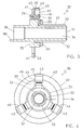
- FIG. 1 and 2 the top half of a rotor 20 is shown.
- the rotor 20 comprises a shaft 21 on which is fitted an armature core 22 comprising a plurality of stacked armature laminations.
- a rotor winding 23 is wound around the armature core to form wound armature poles.
- a commutator 30 is fitted to the shaft 21 adjacent the armature core 22.
- the commutator comprises a commutator base 31, a number of commutator segments 32 and a retaining ring 33.
- the commutator base is moulded from a suitable plastics material such as phenolic or nylon and has a segment support portion 34, a collar 35 and a spacer portion 36.
- the spacer portion 36 abuts the armature core 22 to axially space the commutator segments 32 from the armature core.
- the commutator segments 32 are retained on the commutator base by a retaining ring 33.
- the commutator segments have a sliding portion 37 for making sliding contact with carbon brushes of the motor and a terminal portion 38 to which connection portions 24 of the armature winding 23 are connected.
- the terminal portion of the commutator is of the weldable type, having a U-shaped tang 39 which faces away from the armature core and around which a connection portion 24 of the winding 23 is looped during winding of the armature core 22, as shown in Figure 1.
- the windings are electrically connected to the commutators by a hot forging process in which the tangs 39 are subjected to heat and pressure to collapse the tangs 39 onto the connection portion 24 and to remove insulation from that portion of the winding wire which is in contact with the tang.
- the tang 39 is seated on and supported by the collar during the forging operation.
- the tang 39 thus takes a form similar to that shown in Figures 2 and 3.
- the commutator has a number of segments corresponding to the number of poles of the rotor although only one is shown for clarity.
- the rotor construction so far described is well known in the art.
- FIG 2 a noise suppression device is shown fitted around the tangs of the commutator.
- the noise suppression device 40 is more clearly shown in Figures 3 and 4.
- the noise suppression device 40 comprises an annular board 41 of non-conductive material supporting a conductive layer 42 which may be, for example, a copper film formed on the board 41.
- the conductive layer has a number of fingers 43 which extend at 90° to the board and are soldered to chip-type capacitors 44.
- Each capacitor 44 has two terminal faces 45 and 46 and is supported by the board by being soldered at its terminal face 45 to one of the fingers 43.
- the other terminal face 46 of the capacitors is soldered to a respective commutator tang.
- the layer forms a star point connection ring connecting one terminal 45 of each of the capacitors together and forming a star connection with the armature windings via the commutators.
- the commutator base 31 has a small projection 36' formed at the end of the spacer portion which cooperates with a recess (not shown) in the armature core to correctly orientate the commutator on the shaft with respect to the armature core to ensure the desired commutation angle.
- Figures 5 and 6 show a slight variation in which the board 41 and conductive layer 42 of the noise suppression device 40 is replaced by a resilient wire ring 47.
- the capacitors 44 are soldered directly to the wire ring on their outer terminal face 45 and soldered directly to the commutator tang 39 on their inner terminal face 46.
- the resilience of the ring can be used to urge the capacitors into contact with the tangs to aid soldering or even avoid the need for soldering in certain arrangements.
- a small amount of flexible adhesive may be used to strengthen the retention of the capacitors under rapid speed changes.
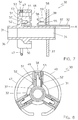
- Figures 7 to 12 refer to a mechanical connection or solderless type commutator such as that described in US Patent specification 4584498.
- the commutator base has a segment support portion 34 and a spacer portion 36 as before.
- the collar 35 is replaced by a crown 50.
- the crown has recesses 51 for accommodating the terminal portion 38 of the commutator segments 32 as well as slots 52 for receiving the connection portions 24 of the winding 23 for connection to the commutator segments 32.
- the crown has further recesses 53, radially outward of the terminal recesses 51, for accommodating the chip-type capacitors 44.
- the top of the capacitor recesses 53 has a slot 54 for receiving the wire ring 47.
- the capacitors 44 are placed axially into the capacitor recesses 53 and the wire ring is resiliently brought to bear on the capacitors' terminal face 45.
- the wire ring 47 bears resiliently on the radially outer edge of the terminal face 45 although of course the wire ring could be soldered to terminal face 45 similar to the embodiment of Figures 5 and 6, except that the capacitors extend axially and with suitable modifications made to the capacitor recesses 53 to accommodate the wire ring 47.
- the capacitors 44 are held in the capacitor recesses 53 by the commutator segments assisted by retaining ring 33, if fitted.
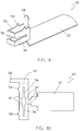
- the commutator segments 32 have a sliding portion 37 similar to that previously described but the terminal portion 38 is formed with a mechanical connection or insulation displacing connection type terminal 55.
- This terminal 55 is accommodated within one of the terminal recesses 51 of the crown.
- the terminal is box-like with an open top and having a slot 56 cut through the forward face and along the two side faces.
- the slot 56 is wider in the front face of the terminal than along the side faces to accommodate an anvil 57 formed within the terminal recesses 51 for supporting the connection portion 24 of the winding 23 as the terminal 55 is inserted into the crown 50.
- the slots 56 straddle and grip the connection portion 24 as the terminal 55 is inserted, at the same time slicing through the insulation of the wire to make electrical contact therewith.
- a finger 58 extends radially from the rear wall of the terminal 55 for making contact with a respective capacitor 44.
- a retaining ring 33 retains the segments on the commutator base and at the same time, supports the fingers 58.
- Barbs 59 formed on the terminals engage with walls of the recesses 51 to resist withdrawal of the terminals from the crown once fitted.
- the commutator segments 32 are fitted to the base by mounting the segments on the base 31 as shown in Figure 7 and then moved in the direction indicated by arrow "A" to insert the terminals 55 into the recesses 51 in the crown 50.
- the retaining ring 33 has been omitted from Figure 8 for clarity from which it can be seen that the fingers 58 extend radially to make contact with the terminal faces 46 of the capacitors 44.
- Figure 10 shows a blank for forming the terminal segment 32 of Figure 9.
- the blank 60 is cut from a sheet of suitable material such as beryllium copper and folded along the five fold lines 61 to form the commutator segment of Figure 9.
- the sliding portion 37 is curved during forming so that the sliding portions of the assembled commutator form a barrel-like cylindrical sliding contact surface.
- Figures 11 and 12 is similar to that of Figures 7 and 8 with the exception that the capacitors 44 extend radially.
- the fingers 58 are bent to extend axially to enter the capacitor recesses 53.
- the capacitor recesses may be open at the front and radially outer sides or the radially outer sides may simply have a slot for accommodating the wire ring 47.
- the wire ring may be soldered to the outer terminal face 45 or if suitably guided by the crown, may be sprung to make direct electrical contact while at the same time, resiliently urging the capacitor into radial contact via its inner terminal face 46 with the finger 58 of the commutator segment, thereby creating a totally solder free noise suppressed commutator assembly.
- the wire ring may or may not be soldered to the capacitor and the capacitor may or may not be soldered to the commutator segments.
- the capacitors have been shown as being placed radially above the terminal portion of the commutator segment, if space permits, the capacitors could be mounted on or above the sliding portion of the commutator segment or accommodated within the terminal recesses of the crown. While for clarity of description, a 3 slot rotor and commutator has been illustrated, rotors of other configurations may be used.
Landscapes
- Engineering & Computer Science (AREA)
- Power Engineering (AREA)
- Physics & Mathematics (AREA)
- Electromagnetism (AREA)
- Motor Or Generator Current Collectors (AREA)
- Dc Machiner (AREA)
- Synchronous Machinery (AREA)
Abstract
Description
- This invention relates to rotors for electric motors and in particular, to rotors for miniature permanent magnet direct current (PMDC) motors incorporating capacitors for suppression of electrical noise.
- Commutators are a major source of electrical noise in miniature PMDC motors. As the brushes transfer from one segment to another, sparks are produced which create electrical noise and increase wear of the commutator and brushes. By suppressing these sparks, the noise level can be reduced and the service life of the motor increased. Varistor or resistor rings may be fitted to the commutator, usually by soldering to tangs used for connecting the winding of the rotor to the commutator, for suppressing these sparks. See for example, GB 2202688. Alternatively, capacitors and/or chokes may be connected to the motor terminals, usually inside the motor end cap or on the brush mounting plate, to suppress the transmission of the noise to the motor's power supply.
- However, better noise suppression has been achieved by connecting capacitors directly to the winding of the rotor. The capacitors may have one lead connected together to form a star point and the other lead connected to a respective commutator tang, there being an equal number of capacitors and poles of the rotor. A known arrangement is shown in GB 2246913 in which the capacitors are electrolytic type capacitors disposed within the winding tunnels of the rotor with the star point connected at the opposite end of the rotor to the commutator.
- While this functions satisfactorily, it has certain drawbacks. It is not particularly suited to automated assembly and as the capacitors are of significant size, this technique cannot be used where the winding tunnels are relatively full of wire.
- The present invention seeks to overcome these problems by providing a wound rotor in which chip capacitors are connected between a star point connection ring and terminal portions of the commutator.
- Accordingly, the present invention provides a rotor for an electric motor comprising a shaft, a commutator fitted to the shaft, an armature core forming a number of poles and a winding wound around the poles and connected to the commutator and noise suppression means, wherein the commutator has a plurality of commutator segments mounted on a commutator base, the segments having contact portions for making sliding contact with the brushes and terminal portions for connection to the winding, wherein, the noise suppression means comprises a plurality of chip-type capacitors, each having a first and second terminal face, each first terminal face being connected to a respective commutator segment and each second terminal face being electrically connected together to form a star point connection.
- By using chip-type capacitors, the superior noise suppression performance by using capacitors mounted on the rotor can be realised even when the winding tunnels are substantially fully occupied by the windings of the rotor.
- Preferably, the second terminal faces are connected together by a conductive ring. This ring may be formed from a sheet material, e.g., brass, or PC board, from conductive rubber rings or strips, or from a length of resilient wire. By forming the ring from resilient wire, the resilience of the wire can be used to assist holding the capacitors in place while they are being soldered to the commutator segments. Indeed, in certain arrangements, the resilient urgings of the ring may be sufficient to maintain good electrical contact between the capacitors and the commutator segments and/or ring, avoiding the need for soldering although soldering the capacitors to the ring may aid assembly in certain embodiments.
- By connecting the capacitors to the terminal portion of the commutator segments, the length of the commutator/rotor can be maintained to a minimum.
- Preferably, the terminal portions are formed with insulation displacing mechanical connection type terminals for connecting with the rotor windings and are accommodated in the crown portion of the commutator base. This allows the construction of the rotor to be solder-free. A positive location for the chip capacitors can be provided by locating the capacitors in recesses or openings formed in the commutator base which may also provide locating means for the ring. Ideally, the capacitors are located radially outward of the terminals.
- The capacitors may be orientated axially or radially and fingers may be formed on the terminal portions and located to make contact with the first terminal face of the capacitors in either the axial or radial direction. If a retaining ring is used to retain the segments on the commutator base, the retaining ring may also retain the capacitors in contact with the commutator segments.
- Preferred embodiments of the invention will now be described, by way of example only, with reference to the accompanying drawings.
- Figure 1 is a schematic side view of a top half of a rotor showing a weldable commutator prior to fixing of rotor winding;
- Figure 2 is a schematic side view of the commutator of Figure 1 after fixing of the rotor winding and fitting of a noise suppressor in accordance with a first embodiment of the present invention;
- Figure 3 is an enlarged sectional view of the commutator of Figure 2 showing the connection of the noise suppressor;
- Figure 4 is an end view of the commutator assembly of Figure 3;
- Figure 5 is a sectional view similar to Figure 3 with an alternative embodiment of the noise suppressor;
- Figure 6 is an end view of the commutator assembly of Figure 5;
- Figure 7 is a schematic cross-section of a partly assembled commutator having a solder-free terminal portion according to an alternative embodiment;
- Figure 8 is an end view of the commutator of Figure 7 once assembled but with a retaining washer omitted for clarity;
- Figure 9 is an isometric view of a segment of the commutator of Figures 7 and 8;
- Figure 10 is a blank for forming the segment of Figure 9;
- Figure 11 is a cross-section of a commutator assembly showing a variation to the arrangement of Figure 7; and
- Figure 12 is an end view of the commutator assembly of Figure 11.
- In Figures 1 and 2, the top half of a
rotor 20 is shown. Therotor 20 comprises ashaft 21 on which is fitted anarmature core 22 comprising a plurality of stacked armature laminations. A rotor winding 23 is wound around the armature core to form wound armature poles. - A
commutator 30 is fitted to theshaft 21 adjacent thearmature core 22. The commutator comprises acommutator base 31, a number ofcommutator segments 32 and aretaining ring 33. The commutator base is moulded from a suitable plastics material such as phenolic or nylon and has asegment support portion 34, acollar 35 and aspacer portion 36. Thespacer portion 36 abuts thearmature core 22 to axially space thecommutator segments 32 from the armature core. Thecommutator segments 32 are retained on the commutator base by aretaining ring 33. - The commutator segments have a sliding
portion 37 for making sliding contact with carbon brushes of the motor and aterminal portion 38 to whichconnection portions 24 of the armature winding 23 are connected. In Figures 1 to 6, the terminal portion of the commutator is of the weldable type, having aU-shaped tang 39 which faces away from the armature core and around which aconnection portion 24 of thewinding 23 is looped during winding of thearmature core 22, as shown in Figure 1. - Once the rotor has been wound, the windings are electrically connected to the commutators by a hot forging process in which the
tangs 39 are subjected to heat and pressure to collapse thetangs 39 onto theconnection portion 24 and to remove insulation from that portion of the winding wire which is in contact with the tang. Thetang 39 is seated on and supported by the collar during the forging operation. Thetang 39 thus takes a form similar to that shown in Figures 2 and 3. - The commutator has a number of segments corresponding to the number of poles of the rotor although only one is shown for clarity. The rotor construction so far described is well known in the art.
- In Figure 2, a noise suppression device is shown fitted around the tangs of the commutator. The
noise suppression device 40 is more clearly shown in Figures 3 and 4. - The
noise suppression device 40 comprises anannular board 41 of non-conductive material supporting aconductive layer 42 which may be, for example, a copper film formed on theboard 41. The conductive layer has a number offingers 43 which extend at 90° to the board and are soldered to chip-type capacitors 44. Eachcapacitor 44 has twoterminal faces terminal face 45 to one of thefingers 43. The otherterminal face 46 of the capacitors is soldered to a respective commutator tang. In the embodiment of Figures 3 and 4, there are 3 capacitors, one for each commutator segment, corresponding to the number of poles of the rotor. As each capacitor is connected to theconductive layer 42, the layer forms a star point connection ring connecting oneterminal 45 of each of the capacitors together and forming a star connection with the armature windings via the commutators. In Figure 3, thecommutator base 31 has a small projection 36' formed at the end of the spacer portion which cooperates with a recess (not shown) in the armature core to correctly orientate the commutator on the shaft with respect to the armature core to ensure the desired commutation angle. - Figures 5 and 6 show a slight variation in which the
board 41 andconductive layer 42 of thenoise suppression device 40 is replaced by aresilient wire ring 47. Thecapacitors 44 are soldered directly to the wire ring on theirouter terminal face 45 and soldered directly to thecommutator tang 39 on theirinner terminal face 46. By soldering the capacitors to thewire ring 47 first, the resilience of the ring can be used to urge the capacitors into contact with the tangs to aid soldering or even avoid the need for soldering in certain arrangements. In some applications, where the capacitors are not soldered to the tangs, a small amount of flexible adhesive may be used to strengthen the retention of the capacitors under rapid speed changes. - Figures 7 to 12 refer to a mechanical connection or solderless type commutator such as that described in US Patent specification 4584498. In this type of commutator, the commutator base has a
segment support portion 34 and aspacer portion 36 as before. However, thecollar 35 is replaced by acrown 50. The crown hasrecesses 51 for accommodating theterminal portion 38 of thecommutator segments 32 as well asslots 52 for receiving theconnection portions 24 of the winding 23 for connection to thecommutator segments 32. - In addition, the crown has further recesses 53, radially outward of the terminal recesses 51, for accommodating the chip-
type capacitors 44. The top of the capacitor recesses 53 has aslot 54 for receiving thewire ring 47. Thecapacitors 44 are placed axially into the capacitor recesses 53 and the wire ring is resiliently brought to bear on the capacitors'terminal face 45. As shown, thewire ring 47 bears resiliently on the radially outer edge of theterminal face 45 although of course the wire ring could be soldered toterminal face 45 similar to the embodiment of Figures 5 and 6, except that the capacitors extend axially and with suitable modifications made to the capacitor recesses 53 to accommodate thewire ring 47. Thecapacitors 44 are held in the capacitor recesses 53 by the commutator segments assisted by retainingring 33, if fitted. - The
commutator segments 32, as shown more clearly in Figure 9, have a slidingportion 37 similar to that previously described but theterminal portion 38 is formed with a mechanical connection or insulation displacingconnection type terminal 55. This terminal 55 is accommodated within one of the terminal recesses 51 of the crown. The terminal is box-like with an open top and having aslot 56 cut through the forward face and along the two side faces. Theslot 56 is wider in the front face of the terminal than along the side faces to accommodate ananvil 57 formed within the terminal recesses 51 for supporting theconnection portion 24 of the winding 23 as the terminal 55 is inserted into thecrown 50. Theslots 56 straddle and grip theconnection portion 24 as the terminal 55 is inserted, at the same time slicing through the insulation of the wire to make electrical contact therewith. - A
finger 58 extends radially from the rear wall of the terminal 55 for making contact with arespective capacitor 44. As shown in Figure 7, a retainingring 33 retains the segments on the commutator base and at the same time, supports thefingers 58.Barbs 59 formed on the terminals engage with walls of therecesses 51 to resist withdrawal of the terminals from the crown once fitted. Thecommutator segments 32 are fitted to the base by mounting the segments on the base 31 as shown in Figure 7 and then moved in the direction indicated by arrow "A" to insert theterminals 55 into therecesses 51 in thecrown 50. - The retaining
ring 33 has been omitted from Figure 8 for clarity from which it can be seen that thefingers 58 extend radially to make contact with the terminal faces 46 of thecapacitors 44. - Figure 10 shows a blank for forming the
terminal segment 32 of Figure 9. The blank 60 is cut from a sheet of suitable material such as beryllium copper and folded along the fivefold lines 61 to form the commutator segment of Figure 9. The slidingportion 37 is curved during forming so that the sliding portions of the assembled commutator form a barrel-like cylindrical sliding contact surface.. - The embodiment of Figures 11 and 12 is similar to that of Figures 7 and 8 with the exception that the
capacitors 44 extend radially. In this arrangement, thefingers 58 are bent to extend axially to enter the capacitor recesses 53. The capacitor recesses may be open at the front and radially outer sides or the radially outer sides may simply have a slot for accommodating thewire ring 47. As previously, the wire ring may be soldered to the outerterminal face 45 or if suitably guided by the crown, may be sprung to make direct electrical contact while at the same time, resiliently urging the capacitor into radial contact via its innerterminal face 46 with thefinger 58 of the commutator segment, thereby creating a totally solder free noise suppressed commutator assembly. - Various modifications may be made to the embodiments described and it is desired to include all such modifications as fall within the scope of the invention as defined in the accompanying claims. For example, the wire ring may or may not be soldered to the capacitor and the capacitor may or may not be soldered to the commutator segments. While in the embodiments, the capacitors have been shown as being placed radially above the terminal portion of the commutator segment, if space permits, the capacitors could be mounted on or above the sliding portion of the commutator segment or accommodated within the terminal recesses of the crown. While for clarity of description, a 3 slot rotor and commutator has been illustrated, rotors of other configurations may be used.
Claims (12)
- A rotor for an electric motor comprising:a shaft (21);an armature core (22) having a number of poles and fitted to the shaft (21);a rotor winding (23) wound around the poles of the armature core (22);a commutator (30) having a base (11) and a plurality of commutator segments (32) fitted to the base (31), each segment (32) having a contact portion (37) for making sliding contact with brushes and a terminal portion (38) for connection to the rotor winding; and noise suppression means (40),characterised in that the noise suppression means (40) comprises a plurality of chip-type capacitors (44), each having first and second terminal faces (45, 46), the first terminal faces (45) being connected together to form a star point connection and the second terminal faces (46) being connected to respective commutator segments.
- A rotor as defined in Claim 1, wherein the first terminal faces (45) are connected together via a ring of conductive material (42, 47).
- A rotor as defined in Claim 2, wherein the ring (42, 47) is fitted resiliently over the capacitors (44) to urge them into contact with the commutator segments.
- A rotor as defined in Claim 2, wherein the capacitors (44) are soldered to the ring (42, 47).
- A rotor as defined in any one of the preceding claims, wherein the capacitors (44) are soldered to the terminal portions (38) ofthe commutator segments (32).
- A rotor as defined in any one of the preceding claims, wherein the commutator (30) has tangs (39) formed on the terminal portion (38) for hot staking the rotor windings (23) and the capacitors (44) are soldered to the tangs (34) after the tangs have been hot staked.
- A rotor as defined in any one of Claims 1 to 5, wherein the terminal portions (38) comprise insulation displacing mechanical connection type terminals (55) for connecting with the rotor winding (23) and are accommodated in a crown portion (50) of the commutator base (31).
- A rotor as defined in Claim 7, wherein the capacitors (44) are located in recesses (53) in the crown portion (50) radially outward of the terminal portions (38).
- A rotor as defined in Claim 8, wherein the capacitors (44) are orientated axially and held in the recesses (53) by fingers (58) formed on the terminal portions (38).
- A rotor as defined in Claim 8, wherein the capacitors (44) are orientated radially and bear radially directly onto respective fingers (58) formed on the terminal portions (38) under the resilient urgings of the ring (47).
- A rotor as defined in Claim 1 wherein the capacitors (44) connect directly to the contact portion (37) ofthe commutator segments (32).
- A rotor as defined in Claim 1 wherein flexible adhesive assists retention of the capacitor (44) in contact with the commutator segment (32).
Priority Applications (1)
| Application Number | Priority Date | Filing Date | Title |
|---|---|---|---|
| EP98108137A EP0863602B1 (en) | 1994-11-24 | 1995-11-21 | A rotor for an electric motor |
Applications Claiming Priority (2)
| Application Number | Priority Date | Filing Date | Title |
|---|---|---|---|
| GB9423689A GB9423689D0 (en) | 1994-11-24 | 1994-11-24 | A rotor for an electric motor |
| GB9423689 | 1994-11-24 |
Related Child Applications (1)
| Application Number | Title | Priority Date | Filing Date |
|---|---|---|---|
| EP98108137A Division EP0863602B1 (en) | 1994-11-24 | 1995-11-21 | A rotor for an electric motor |
Publications (3)
| Publication Number | Publication Date |
|---|---|
| EP0714159A2 true EP0714159A2 (en) | 1996-05-29 |
| EP0714159A3 EP0714159A3 (en) | 1997-03-05 |
| EP0714159B1 EP0714159B1 (en) | 1999-03-03 |
Family
ID=10764888
Family Applications (2)
| Application Number | Title | Priority Date | Filing Date |
|---|---|---|---|
| EP95308323A Expired - Lifetime EP0714159B1 (en) | 1994-11-24 | 1995-11-21 | A rotor for an electric motor |
| EP98108137A Expired - Lifetime EP0863602B1 (en) | 1994-11-24 | 1995-11-21 | A rotor for an electric motor |
Family Applications After (1)
| Application Number | Title | Priority Date | Filing Date |
|---|---|---|---|
| EP98108137A Expired - Lifetime EP0863602B1 (en) | 1994-11-24 | 1995-11-21 | A rotor for an electric motor |
Country Status (12)
| Country | Link |
|---|---|
| US (1) | US5717270A (en) |
| EP (2) | EP0714159B1 (en) |
| JP (1) | JP3766129B2 (en) |
| KR (1) | KR960019913A (en) |
| CN (1) | CN1055800C (en) |
| BR (1) | BR9505510A (en) |
| CZ (1) | CZ286964B6 (en) |
| DE (2) | DE69508040T2 (en) |
| ES (2) | ES2178796T3 (en) |
| GB (1) | GB9423689D0 (en) |
| IN (1) | IN185776B (en) |
| PL (1) | PL178956B1 (en) |
Cited By (5)
| Publication number | Priority date | Publication date | Assignee | Title |
|---|---|---|---|---|
| EP0902524A1 (en) | 1997-09-15 | 1999-03-17 | Interelectric Ag | DC Motor |
| EP0818873A3 (en) * | 1996-07-10 | 1999-08-18 | Johnson Electric S.A. | A miniature motor |
| DE10021392C2 (en) * | 2000-05-03 | 2002-09-12 | Interelectric Ag Holding Sachs | Coreless electric motor |
| EP3026789A1 (en) * | 2014-11-27 | 2016-06-01 | Valeo Equipements Electriques Moteur | Rotor of a motor vehicle starter provided with a protective layer on the lug |
| CN106385138A (en) * | 2016-11-01 | 2017-02-08 | 蔡甫寒 | Electromagnetic interference suppression structure of DC motor commutator |
Families Citing this family (22)
| Publication number | Priority date | Publication date | Assignee | Title |
|---|---|---|---|---|
| US5903072A (en) * | 1997-03-21 | 1999-05-11 | Fasco Industries, Inc. | Electric motor input circuit with leadless capacitor assembly |
| US6078117A (en) * | 1997-08-27 | 2000-06-20 | Nartron Corporation | End cap assembly and electrical motor utilizing same |
| FR2774525B1 (en) * | 1998-02-03 | 2000-03-31 | Meritor Light Vehicle Sys Ltd | ANTI-INTERFERENCE SYSTEM OF A PERMANENT MAGNET MOTOR FOR ACTIVATION OF A FUNCTIONAL MEMBER OF A MOTOR VEHICLE |
| JP3559181B2 (en) * | 1998-11-30 | 2004-08-25 | 三菱電機株式会社 | Motor for electric power steering system |
| JP4358391B2 (en) * | 1999-11-22 | 2009-11-04 | 株式会社 五十嵐電機製作所 | Method of connecting ring-shaped electric noise prevention element to commutator in electric motor, and commutator including electric noise prevention element connected by the method |
| CN1192470C (en) * | 1999-11-25 | 2005-03-09 | 马渊马达株式会社 | Small-sized motor |
| DE10233712B3 (en) * | 2002-07-24 | 2004-02-12 | Kolektor D.O.O. | Drum commutator for an electrical machine |
| DE102004003146B4 (en) * | 2003-01-22 | 2023-08-24 | Aisan Kogyo Kabushiki Kaisha | Motor, fuel pump, commutator and method of making a commutator |
| DE10306516A1 (en) * | 2003-02-14 | 2004-09-16 | Kolektor D.O.O. | Commutator for an electrical machine |
| DE10354220A1 (en) * | 2003-11-20 | 2005-06-30 | Kolektor D.O.O. | Commutator for an electric machine |
| US7088028B2 (en) * | 2004-05-25 | 2006-08-08 | Microplex Ntp, Ltd. | Ring cap for use on commutator in miniature electric motor for absorbing electrical noise/sound |
| US7015608B2 (en) * | 2004-07-27 | 2006-03-21 | Delco Remy International, Inc. | Method and apparatus to suppress electrical noise in a rotor assembly for an electrical machine |
| JP4157092B2 (en) * | 2004-11-29 | 2008-09-24 | Tdk株式会社 | motor |
| US20080088187A1 (en) * | 2006-10-17 | 2008-04-17 | Hitachi, Ltd | Electric Motor with Reduced EMI |
| US7696656B2 (en) * | 2007-12-20 | 2010-04-13 | Calsonickansei North America, Inc. | Motor assembly incorporating a securely positioned electromagnetic disturbance suppression device |
| US9819241B2 (en) * | 2010-06-14 | 2017-11-14 | Black & Decker Inc. | Stator assembly for a brushless motor in a power tool |
| FR2974968B1 (en) * | 2011-05-03 | 2013-07-05 | Aldebaran Robotics S A | PRINTED CIRCUIT FOR ENSURING THE CONNECTION OF AN ELECTRIC MOTOR AND AN ELECTRIC MOTOR COMPRISING THE PRINTED CIRCUIT |
| KR101389414B1 (en) * | 2013-02-04 | 2014-04-28 | 한양대학교 산학협력단 | Magnet motor transmitting current using capacitor |
| JP5682649B2 (en) * | 2013-03-28 | 2015-03-11 | 三菱電機株式会社 | Rotating electric machine |
| DE102013222336A1 (en) * | 2013-11-04 | 2015-05-07 | Robert Bosch Gmbh | Entstöreinrichtung, electric motor with a suppression device and use of the electric motor |
| CN105429415B (en) * | 2015-12-23 | 2018-12-18 | 中电电机股份有限公司 | A kind of commutating pole structure |
| WO2021247954A1 (en) | 2020-06-05 | 2021-12-09 | Milwaukee Electric Tool Corporation | Brushless motor for a power tool |
Citations (3)
| Publication number | Priority date | Publication date | Assignee | Title |
|---|---|---|---|---|
| US4584498A (en) | 1982-10-11 | 1986-04-22 | Johnson Electric Industrial Manufactory Limited | Commutator with winding connections |
| GB2202688A (en) | 1987-02-27 | 1988-09-28 | Mabuchi Motor Co | Mounting spark-quenching element to commutator |
| GB2246913A (en) | 1990-07-23 | 1992-02-12 | Mabuchi Motor Co | Maintaining rotor balance in an electric motor |
Family Cites Families (18)
| Publication number | Priority date | Publication date | Assignee | Title |
|---|---|---|---|---|
| US3322988A (en) * | 1963-12-25 | 1967-05-30 | Jeco Kk | Direct current armature with condensers |
| US3488538A (en) * | 1967-08-29 | 1970-01-06 | Shigeru Hayashi | Spark suppressing arrangement for commutators |
| DE6803418U (en) * | 1968-10-23 | 1969-03-13 | Gebr Buehler Nachf Gmbh | SMALL ELECTRIC MOTOR |
| JPS585426Y2 (en) * | 1976-04-21 | 1983-01-29 | マブチモ−タ−株式会社 | Micro motor spark quencher |
| JPS5417008U (en) * | 1977-07-08 | 1979-02-03 | ||
| JPS5541138A (en) * | 1978-09-12 | 1980-03-22 | Matsushita Electric Ind Co Ltd | Miniature motor |
| GB2063577B (en) * | 1979-09-05 | 1983-05-11 | Mabuchi Motor Co | Motor |
| US4329605A (en) * | 1980-10-14 | 1982-05-11 | General Motors Corporation | Electric motor having radio frequency interference radiation suppression |
| JPS5822569A (en) * | 1981-07-31 | 1983-02-09 | Matsushita Electric Works Ltd | Motor |
| JPS59169351A (en) * | 1983-03-15 | 1984-09-25 | Matsushita Electric Works Ltd | Condenser mounting structure to rotor of motor |
| SU1169058A1 (en) * | 1984-02-07 | 1985-07-23 | Предприятие П/Я Г-4651 | Armature for electric machine |
| JPS622358U (en) * | 1985-06-18 | 1987-01-08 | ||
| GB2202686B (en) * | 1987-03-23 | 1991-08-14 | Johnson Electric Ind Mfg | An armature for an electric motor |
| GB2207292A (en) * | 1987-07-09 | 1989-01-25 | Johnson Electric Ind Mfg | Electric motor |
| US5003208A (en) * | 1988-08-31 | 1991-03-26 | Mabuchi Motor Co. Ltd. | Miniature motor having positive-coefficient thermistor |
| GB2224165A (en) * | 1988-09-22 | 1990-04-25 | Johnson Electric Ind Mfg | Suppression element in a commutator |
| JPH03270662A (en) * | 1990-03-16 | 1991-12-02 | Hitachi Ltd | Motor having brush |
| JP2510549Y2 (en) * | 1991-12-17 | 1996-09-11 | マブチモーター株式会社 | Small motor |
-
1994
- 1994-11-24 GB GB9423689A patent/GB9423689D0/en active Pending
-
1995
- 1995-11-20 CZ CZ19953057A patent/CZ286964B6/en not_active IP Right Cessation
- 1995-11-21 US US08/560,208 patent/US5717270A/en not_active Expired - Fee Related
- 1995-11-21 DE DE69508040T patent/DE69508040T2/en not_active Expired - Fee Related
- 1995-11-21 DE DE69527993T patent/DE69527993T2/en not_active Expired - Fee Related
- 1995-11-21 EP EP95308323A patent/EP0714159B1/en not_active Expired - Lifetime
- 1995-11-21 ES ES98108137T patent/ES2178796T3/en not_active Expired - Lifetime
- 1995-11-21 EP EP98108137A patent/EP0863602B1/en not_active Expired - Lifetime
- 1995-11-21 JP JP30263995A patent/JP3766129B2/en not_active Expired - Fee Related
- 1995-11-21 ES ES95308323T patent/ES2128670T3/en not_active Expired - Lifetime
- 1995-11-22 KR KR1019950042933A patent/KR960019913A/en not_active Ceased
- 1995-11-23 IN IN1512CA1995 patent/IN185776B/en unknown
- 1995-11-23 PL PL95311469A patent/PL178956B1/en not_active IP Right Cessation
- 1995-11-23 BR BR9505510A patent/BR9505510A/en not_active IP Right Cessation
- 1995-11-24 CN CN95121859A patent/CN1055800C/en not_active Expired - Fee Related
Patent Citations (3)
| Publication number | Priority date | Publication date | Assignee | Title |
|---|---|---|---|---|
| US4584498A (en) | 1982-10-11 | 1986-04-22 | Johnson Electric Industrial Manufactory Limited | Commutator with winding connections |
| GB2202688A (en) | 1987-02-27 | 1988-09-28 | Mabuchi Motor Co | Mounting spark-quenching element to commutator |
| GB2246913A (en) | 1990-07-23 | 1992-02-12 | Mabuchi Motor Co | Maintaining rotor balance in an electric motor |
Cited By (7)
| Publication number | Priority date | Publication date | Assignee | Title |
|---|---|---|---|---|
| EP0818873A3 (en) * | 1996-07-10 | 1999-08-18 | Johnson Electric S.A. | A miniature motor |
| EP0902524A1 (en) | 1997-09-15 | 1999-03-17 | Interelectric Ag | DC Motor |
| US6144133A (en) * | 1997-09-15 | 2000-11-07 | Interelectric Ag | Direct current electromotor |
| DE10021392C2 (en) * | 2000-05-03 | 2002-09-12 | Interelectric Ag Holding Sachs | Coreless electric motor |
| EP3026789A1 (en) * | 2014-11-27 | 2016-06-01 | Valeo Equipements Electriques Moteur | Rotor of a motor vehicle starter provided with a protective layer on the lug |
| FR3029364A1 (en) * | 2014-11-27 | 2016-06-03 | Valeo Equip Electr Moteur | STARTER ROTOR FOR MOTOR VEHICLE WITH PROTECTIVE LAYER ON THE HEEL |
| CN106385138A (en) * | 2016-11-01 | 2017-02-08 | 蔡甫寒 | Electromagnetic interference suppression structure of DC motor commutator |
Also Published As
| Publication number | Publication date |
|---|---|
| EP0863602B1 (en) | 2002-08-28 |
| BR9505510A (en) | 1997-10-28 |
| JPH08228458A (en) | 1996-09-03 |
| DE69527993D1 (en) | 2002-10-02 |
| EP0714159A3 (en) | 1997-03-05 |
| DE69527993T2 (en) | 2003-03-20 |
| CZ286964B6 (en) | 2000-08-16 |
| EP0714159B1 (en) | 1999-03-03 |
| IN185776B (en) | 2001-04-28 |
| JP3766129B2 (en) | 2006-04-12 |
| GB9423689D0 (en) | 1995-01-11 |
| CN1134058A (en) | 1996-10-23 |
| CN1055800C (en) | 2000-08-23 |
| PL311469A1 (en) | 1996-05-27 |
| ES2178796T3 (en) | 2003-01-01 |
| EP0863602A1 (en) | 1998-09-09 |
| US5717270A (en) | 1998-02-10 |
| DE69508040T2 (en) | 1999-09-16 |
| KR960019913A (en) | 1996-06-17 |
| CZ305795A3 (en) | 1996-06-12 |
| ES2128670T3 (en) | 1999-05-16 |
| PL178956B1 (en) | 2000-07-31 |
| DE69508040D1 (en) | 1999-04-08 |
Similar Documents
| Publication | Publication Date | Title |
|---|---|---|
| US5717270A (en) | Noise suppression capacitor arrangement on a rotor of an electric motor | |
| US4851730A (en) | Brush holder assembly for electric motor | |
| EP0236254A2 (en) | Brush holder for dynamoelectric machines | |
| GB2248348A (en) | Supporting suppression elements on a brush holder | |
| KR100624669B1 (en) | Motor with grounding structure to reduce radio noise | |
| CN109245393B (en) | Motor, end cover of motor and manufacturing method of end cover | |
| EP0509683B1 (en) | Miniature motor | |
| EP0682400A1 (en) | Noise suppressed commutator | |
| US20220247141A1 (en) | Electric motor with connecting element for a winding of a stator on a printed circuit board with at least two insulation displacement contacts | |
| EP1388924B1 (en) | Electric motor | |
| JPH07194063A (en) | Connection method for small motors and electronic components with built-in motors | |
| EP0607032A1 (en) | Miniature motor | |
| EP1168575B1 (en) | Star connected rotor | |
| JPH09252557A (en) | Electric motor | |
| GB2205451A (en) | Connecting brush holders and suppression element to stator windings of an electric motor | |
| US5218254A (en) | Miniature motors end cap brush and terminal assembly | |
| EP0650243A1 (en) | Brush assembly | |
| GB2389242A (en) | Varistor assembly for motor noise suppression | |
| EP0463889B1 (en) | Electric-powered tool | |
| US20020121836A1 (en) | End shield for a commutator machine and a method for producing such an end shield | |
| GB2207292A (en) | Electric motor | |
| GB2203292A (en) | Suppressor connection for commutator segment | |
| JP5682649B2 (en) | Rotating electric machine | |
| JP2004229438A (en) | Small-sized motor with brush | |
| JPH0799755A (en) | Compact motor |
Legal Events
| Date | Code | Title | Description |
|---|---|---|---|
| PUAI | Public reference made under article 153(3) epc to a published international application that has entered the european phase |
Free format text: ORIGINAL CODE: 0009012 |
|
| AK | Designated contracting states |
Kind code of ref document: A2 Designated state(s): DE ES FR GB IT |
|
| PUAL | Search report despatched |
Free format text: ORIGINAL CODE: 0009013 |
|
| AK | Designated contracting states |
Kind code of ref document: A3 Designated state(s): DE ES FR GB IT |
|
| 17P | Request for examination filed |
Effective date: 19970723 |
|
| 17Q | First examination report despatched |
Effective date: 19971222 |
|
| GRAG | Despatch of communication of intention to grant |
Free format text: ORIGINAL CODE: EPIDOS AGRA |
|
| GRAG | Despatch of communication of intention to grant |
Free format text: ORIGINAL CODE: EPIDOS AGRA |
|
| GRAH | Despatch of communication of intention to grant a patent |
Free format text: ORIGINAL CODE: EPIDOS IGRA |
|
| GRAH | Despatch of communication of intention to grant a patent |
Free format text: ORIGINAL CODE: EPIDOS IGRA |
|
| GRAA | (expected) grant |
Free format text: ORIGINAL CODE: 0009210 |
|
| AK | Designated contracting states |
Kind code of ref document: B1 Designated state(s): DE ES FR GB IT |
|
| REF | Corresponds to: |
Ref document number: 69508040 Country of ref document: DE Date of ref document: 19990408 |
|
| ET | Fr: translation filed | ||
| REG | Reference to a national code |
Ref country code: ES Ref legal event code: FG2A Ref document number: 2128670 Country of ref document: ES Kind code of ref document: T3 |
|
| PLBE | No opposition filed within time limit |
Free format text: ORIGINAL CODE: 0009261 |
|
| STAA | Information on the status of an ep patent application or granted ep patent |
Free format text: STATUS: NO OPPOSITION FILED WITHIN TIME LIMIT |
|
| 26N | No opposition filed | ||
| REG | Reference to a national code |
Ref country code: GB Ref legal event code: IF02 |
|
| PGFP | Annual fee paid to national office [announced via postgrant information from national office to epo] |
Ref country code: DE Payment date: 20081114 Year of fee payment: 14 |
|
| PGFP | Annual fee paid to national office [announced via postgrant information from national office to epo] |
Ref country code: ES Payment date: 20081216 Year of fee payment: 14 |
|
| PGFP | Annual fee paid to national office [announced via postgrant information from national office to epo] |
Ref country code: IT Payment date: 20081125 Year of fee payment: 14 |
|
| PGFP | Annual fee paid to national office [announced via postgrant information from national office to epo] |
Ref country code: FR Payment date: 20081112 Year of fee payment: 14 |
|
| PGFP | Annual fee paid to national office [announced via postgrant information from national office to epo] |
Ref country code: GB Payment date: 20081119 Year of fee payment: 14 |
|
| GBPC | Gb: european patent ceased through non-payment of renewal fee |
Effective date: 20091121 |
|
| REG | Reference to a national code |
Ref country code: FR Ref legal event code: ST Effective date: 20100730 |
|
| PG25 | Lapsed in a contracting state [announced via postgrant information from national office to epo] |
Ref country code: FR Free format text: LAPSE BECAUSE OF NON-PAYMENT OF DUE FEES Effective date: 20091130 |
|
| PG25 | Lapsed in a contracting state [announced via postgrant information from national office to epo] |
Ref country code: DE Free format text: LAPSE BECAUSE OF NON-PAYMENT OF DUE FEES Effective date: 20100601 |
|
| PG25 | Lapsed in a contracting state [announced via postgrant information from national office to epo] |
Ref country code: GB Free format text: LAPSE BECAUSE OF NON-PAYMENT OF DUE FEES Effective date: 20091121 |
|
| REG | Reference to a national code |
Ref country code: ES Ref legal event code: FD2A Effective date: 20110328 |
|
| PG25 | Lapsed in a contracting state [announced via postgrant information from national office to epo] |
Ref country code: IT Free format text: LAPSE BECAUSE OF NON-PAYMENT OF DUE FEES Effective date: 20091121 |
|
| PG25 | Lapsed in a contracting state [announced via postgrant information from national office to epo] |
Ref country code: ES Free format text: LAPSE BECAUSE OF NON-PAYMENT OF DUE FEES Effective date: 20110315 |
|
| PG25 | Lapsed in a contracting state [announced via postgrant information from national office to epo] |
Ref country code: ES Free format text: LAPSE BECAUSE OF NON-PAYMENT OF DUE FEES Effective date: 20091122 |