EP0718155A1 - Modular system for transporting luggage on the roof of a motor vehicle - Google Patents
Modular system for transporting luggage on the roof of a motor vehicle Download PDFInfo
- Publication number
- EP0718155A1 EP0718155A1 EP95120084A EP95120084A EP0718155A1 EP 0718155 A1 EP0718155 A1 EP 0718155A1 EP 95120084 A EP95120084 A EP 95120084A EP 95120084 A EP95120084 A EP 95120084A EP 0718155 A1 EP0718155 A1 EP 0718155A1
- Authority
- EP
- European Patent Office
- Prior art keywords
- containers
- roof
- motor vehicle
- retention
- guide
- Prior art date
- Legal status (The legal status is an assumption and is not a legal conclusion. Google has not performed a legal analysis and makes no representation as to the accuracy of the status listed.)
- Granted
Links
- 230000014759 maintenance of location Effects 0.000 claims abstract description 21
- 230000008878 coupling Effects 0.000 claims description 7
- 238000010168 coupling process Methods 0.000 claims description 7
- 238000005859 coupling reaction Methods 0.000 claims description 7
- 230000003287 optical effect Effects 0.000 claims description 7
- 239000000463 material Substances 0.000 claims description 2
- 239000004033 plastic Substances 0.000 claims description 2
- 229920003023 plastic Polymers 0.000 claims description 2
- 229920001343 polytetrafluoroethylene Polymers 0.000 claims description 2
- 230000011664 signaling Effects 0.000 claims description 2
- -1 polytetrafluoroethylene Polymers 0.000 claims 1
- 239000004810 polytetrafluoroethylene Substances 0.000 claims 1
- 230000002829 reductive effect Effects 0.000 description 6
- 230000000670 limiting effect Effects 0.000 description 2
- 238000004873 anchoring Methods 0.000 description 1
- 239000000446 fuel Substances 0.000 description 1
- 230000009191 jumping Effects 0.000 description 1
- 230000036961 partial effect Effects 0.000 description 1
- 230000000284 resting effect Effects 0.000 description 1
- 230000000717 retained effect Effects 0.000 description 1
Images


Classifications
-
- B—PERFORMING OPERATIONS; TRANSPORTING
- B60—VEHICLES IN GENERAL
- B60R—VEHICLES, VEHICLE FITTINGS, OR VEHICLE PARTS, NOT OTHERWISE PROVIDED FOR
- B60R9/00—Supplementary fittings on vehicle exterior for carrying loads, e.g. luggage, sports gear or the like
- B60R9/04—Carriers associated with vehicle roof
- B60R9/055—Enclosure-type carriers, e.g. containers, boxes
Definitions
- the present invention relates to a system for transporting luggage and the like on the roof of a motor vehicle.
- the subject of the invention is a system comprising retention and guide means which can be secured on the motor vehicle roof and a plurality of suitcase-like containers which can be removably anchored to these retention and guide means.
- the object of the present invention is to provide a system for transporting luggage and the like on the roof of a motor vehicle, which system is simple, convenient and reliable to use, and which in the operating state does not appreciably impair the overall aerodynamics of the motor vehicle and thus its performance in terms of fuel consumption and speed, and which is furthermore stylistically integrated in the aesthetic appearance of the motor vehicle as a whole.
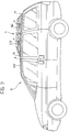
- a motor vehicle is designated M on the roof R of which is mounted a modular system, generally designated S, for transporting luggage and the like.
- this transporting system S comprises three pairs of substantially suitcase-like containers (1, 2), (3, 4) and (5, 6) which are anchored to and are removable from a supporting retention and guide structure secured to the roof R, which will be described in further detail below.
- the containers 1, 3 and 5 have respective shapes which are mirror images of those of the adjacent containers 2, 4 and 6.
- the widths L ( Figure 2) of these containers are substantially less than or equal to half the width of the motor vehicle roof R.
- the containers 1 and 2 of the first pair have an aerodynamic profile which is substantially wedge-shaped.
- the containers of the other two pairs 3, 4 and 5, 6 have shapes which are relatively more squared.
- the containers 1 to 6 have respective handles H on the respective faces which, in the assembled state of use ( Figure 1), are turned towards the body sides of the motor vehicle M.
- a retention and guide structure substantially comprising a central profiled portion 7 with a substantially H-shaped section, resting on and secured to the motor vehicle roof R in correspondence with one of its parallel legs. At its sides, this profiled portion 7 defines two substantially symmetrical longitudinal guides or channels 8 (see also Figure 4).
- the retention and guide structure also comprises two further profiled portions 9 which have substantially C-shaped sections and are disposed symmetrically on opposite sides relative to the central profiled portion 7, along the longitudinal sides of the roof.
- the respective longitudinal recesses or guides 10 in the profiled portions 9 face the guides 8 defined in the central profiled portion 7.
- FIGS 2, 3 and 3a show, two pairs of fins 11 and 12 respectively, which are substantially folded in an L-shape and have their free ends directed towards the exterior, are secured to the faces of the containers 1-6 which are to be turned towards the motor vehicle roof R.
- the fins 11 of these containers can be slidingly engaged in the guide grooves 10 of the lateral profiled portions 9 whilst the fins 12 can be slidingly engaged in the guide channels 8 of the central profiled portion 7 (see Figure 4).
- the upper flanges 7a, 9a of the rear ends of the profiled portions can be shortened, as shown in Figure 2 and in the details illustrated in Figures 2b and 2c.
- the front ends of the channels or guides 8, 10 of the profiled portions 7 and 9 respectively are transversely closed, as shown for example in Figure 2a, in order to stop the sliding of the fins 11, 12 of the first pair of containers 1, 2 and to define their stop limit position.
- the containers 1-6 can be disposed adjacent one another on the motor vehicle roof R by engaging the fins 11 and 12 in the guide channels of the profiled portions 7 and 9.
- the containers 3, 4 and 5, 6 advantageously have respective shapes such that, adjacent the containers 1, 2 of the first pair, in the state of use in which they are close to each other (Figure 1), they form an overall volume of aerodynamic shape which is substantially wedge-shaped.
- the arcuate wedge-shaped profile of the first pair of containers 1, 2 enables the overall shape of these containers to be harmoniously and aesthetically combined with the general shape of the motor vehicle M.
- the containers 1-6 can be locked by coupling a suitable locking device indicated 13 in Figures 2, 2d, 5 and 6 to the rear end of the central profiled portion 7.
- the locking device 13 comprises a body 14 having on one face a recess 15 which can be coupled to the rear end portion of the central core 7b of the profiled portion 7 ( Figures 2b, 5 and 6).
- This core 7b is, for example, tubular and has an upper slot-like aperture indicated 16 in Figures 2b, 5 and 6.
- a device with a lock 17, of substantially known type, which can be actuated by means of a key 18 is mounted in the body 14 of the locking device.
- This device comprises a lock cylinder 19 which can rotate about and be moved along an axis which is indicated X-X in Figure 5 and passes through the slot-like aperture 16 when the locking device 13 is coupled to the profiled portion 7.
- a rod 20, into the open end of which a pin 21 is driven, is connected to the cylinder 19.
- Disposed about this rod is a helical spring 22 which, reacting on the one side against a ring 23 secured to the body 14 and on the other against the cylinder 19, tends to oppose the translation of the latter.
- the locking device 13 is coupled to the end portion of the central profiled portion 7, in the manner illustrated in Figure 5, with the cylinder 19 in the extracted state.
- the user can cause the cylinder 19 to move downwards in such a way that the pin 21 of the rod 20 projects beyond the slot-like aperture 16 of the end portion of the core of the profiled portion 7.
- the rotation of the key 18 determines the engagement of the pin 21 below the upper wall of the core 7b of the profiled portion 7.
- the locking device is firmly retained at the rear end of the central profiled portion 7 and its body 14 prevents the containers 1-6 being removed from the profiled portions 7 to 9.
- a microswitch such as the one indicated 24 in Figures 5 and 6, which can be actuated by the end of the pin 21 when the latter is in the locking position shown in Figure 6, can be disposed inside the recess in the tubular core 7b of the central profiled portion 7, adjacent the slot-like aperture 16.
- the microswitch 24 can advantageously be used to generate an electrical signal indicating that the assembly of the containers 1-6 has been locked in position on the motor vehicle roof, it being possible to use this signal, for example, in order to generate a corresponding optical or acoustic signal inside the motor vehicle passenger compartment.
- microswitches can also be used in conjunction with the anti-theft alarm with which the motor vehicle may be equipped in order to determine the generation of an alarm signal when the luggage-transporting containers are in some manner unlawfully removed from the motor vehicle roof whilst the anti-theft system is activated.
- the central profiled portion 7, or the lateral profiled portions 9, can be provided (in a manner not shown) with possible microswitches or other sensors of known type, which can cooperate, for example, with the fins 11 or 12 of the containers 1, in order to provide corresponding electrical signals indicating the presence of the containers 1-6 in the respective anchorage positions on the motor vehicle roof.
- These signals can be used, for example, to determine the generation of an acoustic or optical signal inside the motor vehicle passenger compartment and/or can be used in conjunction with the anti-theft alarm system with which the vehicle may be equipped.
- the modular structure of the transporting system according to the invention enables configurations with reduced carrying capacities to be produced, as shown in Figures 7 and 8.
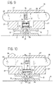
- the central profiled portion 7 can have an aperture 25 for anchoring a front locking device which is indicated 26 in the same Figure.
- This locking device is also shown in Figures 2e and 7 and is to function as a stop for the front pair of containers 1, 2 in the reduced configuration of the transporting system.
- the front locking device 26 comprises a body 27 through which extend two opposite members 28 and 29 between which a spring 30 tending to urge them in opposite directions is interposed.
- the members 28 and 29 have respective ends which project on the exterior of the body 27 and which can be actuated such that they approach each other, against the action of the spring 30, in the manner of push buttons.
- the members 27, 28 and 29 comprise respective appendages 31, 32 of which the distal ends form respective coupling teeth 33, 34.
- the user presses the push buttons 28 and 29 towards each other, such that their appendages 31, 32 are brought into the approached state.
- the locking device 26 is applied to the front profiled portion 7, such that the coupling teeth 33, 34 extend through the aperture 25, as shown in Figure 9.
- the user then releases the push buttons 28 and 29, which move apart under the action of the spring 30, such that the respective coupling teeth 33 and 34 engage below opposite edge portions of the aperture 25, as shown in Figure 10.
- the front locking device 26 is firmly restrained on the central profiled portion. 7 in order to define the stop position of the pair of front containers 1, 2 in the transporting configuration with reduced capacity.
- the user can then fit these containers 1, 2 and the following pair of containers (for example) 5 and 6 in the profiled portions and lock the assembly formed of these four containers at the rear using the rear locking device 13 described above ( Figure 7).
- the central profiled portion 7 can have a further aperture 35 (Figure 2) enabling the front locking device 26 to be anchored further back, in order to permit the single pair of containers 1 and 2 to be anchored to the profiled portions 7 and 9, as shown in Figure 8, in order to reduce the carrying capacity even further.
- the locking device 26 can be produced in such a way that it can be locked in the anchorage position to the central profiled portion 7 by means of a device having a lock which can be actuated by means of a key.
- the locking device 26 can comprise a shaft 36 rotatably mounted in the body 27, in the area between the members 28 and 29.
- This shaft 36 is advantageously provided with two opposite radial appendages 37 and can be disposed in one angular position ( Figure 9) in which these appendages enable the members 28 and 29 to approach each other to an extent sufficient to enable the locking device to be disengaged from the profiled portion 7 and in a second angular position ( Figure 10) in which this disengagement is prevented.
- the placing of the shaft 36 in the angular position shown in Figure 10 can be controlled by means of a lock and key.
- the transporting system having a modular structure described hitherto has numerous advantages. Firstly, it can assume a plurality of configurations with various carrying capacities, as necessary. In all the possible transporting configurations, the system is nevertheless aesthetically and aerodynamically well-integrated in the general shape of the motor vehicle.
- the individual containers provided in the system are, in fact, suitcases which, in spite of their rather particular shape, are adequately capacious and easy to handle.
- the system according to the invention is advantageously used on both small and large motor vehicles and in particular on those motor vehicles which, when used with the maximum number of occupants permitted, have a limited amount of space available for transporting luggage and the like.
- an optical display panel such as the one indicated 40 in Figure 11, can be disposed inside the motor vehicle passenger compartment.
- This panel comprises a plurality of optical indicators I1-I6 each of which is associated with a corresponding container 1-6.
- a further optical indicator I7 can advantageously be associated with the rear locking device 13.
- the panel 40 can be connected to the motor vehicle check control system, in order to provide the driver with a luminous signal indicating that the containers 1 to 6 are correctly positioned and that the rear locking device 13 has been locked, before the motor vehicle engine is started.
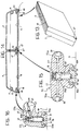
- a central strip secured to the longitudinal centre line of the roof, and two longitudinal side strips 49, adjacent the longitudinal sides of the roof, are applied to the motor vehicle roof R.
- the central strip 47 and the side strips 49 have grooves or channels 50 and 51 respectively on their respective sides.
- first and second guide elements indicated 52 and 53 respectively are coupled to the strips 47 and 49. These guide elements are locked (as will be described below) in respective operating positions along the strips, at distances which are shorter than the lengths of the containers 1 to 6.
- the guide elements 52 anchored to the central strip 47 have a substantially T-shaped section, with respective flanges 52a projecting transversely relative to this strip (see Figures 12a and 15 for example).
- the lower ends of the legs of these guide elements 52 form pairs of fins which face one another, indicated 52b in Figure 15, and which can be slidingly engaged in the channels 50 in the strip 47.
- this strip advantageously has apertures such as those indicated 54 in Figure 15, in which the lower end of a rod 55 displaceably mounted inside the guide element can be engaged.
- the rod 55 is loaded at the top by a helical spring 56 which tends to cause it to protrude at the bottom.
- the rod 55 has an intermediate portion 55a which is substantially conical and which can cooperate with two opposite transverse control rods 57 the ends of which extend in recesses in the flanges 52a of the guide element 52, there forming respective heads 58.
- the user presses the heads 58, causing the rod 55 to withdraw into the body of the guide element 52.
- the user fits the flanges 52b of the guide element into the corresponding channels 50 in the strip 47.
- the guide element is made to slide to the required position and, when this position is reached, the user releases the heads 58 and the rod 55 engages the recess 54 in the strip 47, under the thrust of the spring 56.
- the guide element 52 which is closest the front side of the roof R has a pair of transverse appendages 52c having a stop function, which will be described in greater detail below.
- the guide elements 53 coupled to the side strips 49 are substantially L-shaped with a leg forming a pair of facing appendages 53a which can engage slidingly in the channels 51 in these strips.
- Each element 53 has a respective flange 53b which extends substantially horizontally in the direction of the central strip 47.
- each of the guide elements 53 In order to anchor each of the guide elements 53 in respective predefined portions along the associated strips 49, the latter have respective apertures, such as those indicated 59 in Figure 16.
- the rod 60 has a tapering intermediate portion 60a in which engages a forked end of a balancing device 62 articulated at 63 and having an end 64 which can be manually engaged in correspondence with a notch 65 in the flange 53b of the guide element.
- each guide element 53 is individually coupled to the associated strips 49 whilst the user pressing on the lever 64 determines the lift of the rod 60. In this state, each guide element 53 can be made to slide along the associated strip 49 to the required locking position and, when this position has been reached, the user releases the lever 64 and the spring 61 forces the rod 60 to engage the aperture 59 in the strip.
- the containers 1 to 6 have respective longitudinal side channels, indicated 66 and 67.
- each container 1-6 can be made to slide along the guide elements 53, 52.
- the channel 66 of each container is made to slide on the flanges 53a of the successive guide elements 53 secured to a strip 49 and the channel 67 slides on the flanges 52a of the guide elements 52.
- the first pair of containers 1, 2 thus abuts the transverse fins 52c of the first guide element 52 anchored to the strip 47.
- the first guide elements 53 can also have respective transverse stop appendages, indicated 53c in Figure 12.
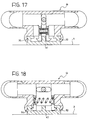
- This locking device preferably comprises an appendage 66a ( Figure 12c) which can be introduced into the rear ends of the channels 67 of the pair of rear containers 5, 6.
- the body of the locking device 66 also has a pair of projecting transverse flanges 66b, intended to press against the rear walls of the containers 5, 6, preventing all possibility of their being moved in the longitudinal direction of the motor vehicle.
- the locking device 66 is stably anchored at the rear end of the central strip 47, for example, in the manner shown clearly in Figures 17 and 18.
- the internal structure of the locking device 66 corresponds substantially to that of the locking device 26 described in detail with reference to Figures 9 and 10. A detailed description of Figures 17 and 18 is thus superfluous and will therefore be omitted.
- the modular transporting system can be used in different configurations corresponding to different load capacities.
- the configuration of maximum capacity, in which all the containers 1-6 are used it is thus possible to produce configurations for transportation with reduced capacity with four or two containers alone, substantially as shown in Figures 7 and 8 in relation to the embodiment described above.
- the guide elements 52, 53 can advantageously be removed and placed, for example, inside the motor vehicle and only the strips 49 remain installed on the roof R, causing a visible or aesthetic "disturbance" which is practically negligible.
- sensor means of known type which can provide electrical signals indicating the presence of the containers in the respective anchorage positions provided, can be associated with the strips 47, 49 or with the guide elements 52, 53.
- a position sensor can further be associated with the rear locking device 66.
- the system provides for the use of a given maximum number of pairs of containers of specular form.
- pairs of parallel guides directed transversely to the longitudinal axis of the roof R, are secured thereto.
- Figure 19 shows in particular six pairs of guides indicated 101 to 106.
- These guides advantageously consist of a plastics material with a low coefficient of friction, for example polytetrafluoroethylene (Teflon), preferably of a colour corresponding to that of the bodywork of the motor vehicle M.
- Teflon polytetrafluoroethylene
- a strip 70 which forms a hooked retaining member for each of the containers 1 to 6 in predetermined positions on the sides is removably secured along the centre line of the roof R.
- these hooked members are indicated 71-76.
- the hooked members 71-76 extend at a spacing from the surface of the roof R.
- the containers 1 to 6 In the respective faces to be turned towards the roof R, the containers 1 to 6 have respective pairs of parallel channels or grooves 81-86 which can engage in a supporting and sliding manner on the associated guides 101-106 applied to this roof.
- the containers 1-6 In the respective faces to be turned towards the longitudinal axis of the roof R, the containers 1-6 have respective recesses 91-96 ( Figure 19) which can be coupled firmly to the associated hooked members 71-76 carried by the strip 70.
- a locking device which can cooperate with the associated hooked retention member of the strip 70 is accommodated in the recess of each container.
- the containers 1 to 6 can be individually supported on the associated guides 101-106 installed on the sides of the vehicle and thus very conveniently. Furthermore, as will become clearer from the following, these containers can be individually mounted and removed from the roof, with obvious advantages in terms of convenience and practicality of use.
- FIGs 20 and 20a show a possible embodiment of the locking device associated with each container, purely by way of example.
- this device comprises a bolt 97 carried by a shaft 98 which can rotate in a base opening 99 adjacent the base of the container.
- the shaft 98 can be actuated in rotation by means of a lock cylinder 110 which is accessible on the side face of the container which, in its state of use, is turned towards the body side of the motor vehicle.
- the bolt 27 can be placed in an angular position in which it engages the notch in the hooked member to which the container is coupled (hooked member 73 in Figures 20 and 20a).
- this hooked member in the associated recess in the container prevents the movement of the container in the vertical direction relative to the part.
- the engagement of the bolt 97 in the notch in the hooked member prevents the container uncoupling from this hooked member.
- they can advantageously be provided with resilient pads on their faces to be turned towards the roof R and towards the adjacent containers. Some of these resilient pads are shown in Figure 20 where they are indicated by the reference numerals 111 and 112.
Landscapes
- Engineering & Computer Science (AREA)
- Mechanical Engineering (AREA)
- Fittings On The Vehicle Exterior For Carrying Loads, And Devices For Holding Or Mounting Articles (AREA)
Abstract
Description
- The present invention relates to a system for transporting luggage and the like on the roof of a motor vehicle.
- More specifically, the subject of the invention is a system comprising retention and guide means which can be secured on the motor vehicle roof and a plurality of suitcase-like containers which can be removably anchored to these retention and guide means.
- The object of the present invention is to provide a system for transporting luggage and the like on the roof of a motor vehicle, which system is simple, convenient and reliable to use, and which in the operating state does not appreciably impair the overall aerodynamics of the motor vehicle and thus its performance in terms of fuel consumption and speed, and which is furthermore stylistically integrated in the aesthetic appearance of the motor vehicle as a whole.
- These and other objects are achieved in accordance with the invention by a modular transporting system of which the principal characteristics are defined in appended
Claim 1. - Particularly advantageous embodiments of the invention are further defined in the subclaims.
- Further characteristics and advantages of the invention will appear from the following detailed description, given purely by way of non-limiting example with reference to the appended drawings, in which:
- Figure 1 is a perspective view of a motor vehicle provided with a modular transporting system according to the invention;
- Figure 2 is a partially exploded perspective view of the motor vehicle and the associated transporting system illustrated in Figure 1;
- Figures 2a-2e are perspective views on an enlarged scale of certain details shown in Figure 2;
- Figure 3 is a perspective view of a container comprised in the modular transporting system according to Figures 1 and 2;
- Figure 3a is a perspective view on an enlarged scale of a detail of the container shown in Figure 3;
- Figure 4 is a view in cross-section of the transporting system according to the preceding Figures, in the mounted state in which it is in use;
- Figure 5 is a view of a locking device shown in Figure 2, taken along the line V-V of this Figure;
- Figure 6 is a view in section similar to that of Figure 5, showing the locking device in a different operating state;
- Figures 7 and 8 are side views of a motor vehicle provided with a transporting system according to the invention, in a first and second reduced configuration;
- Figure 9 is a view in section of a further locking device shown in Figures 2 and 2e, taken along the line IX-IX of Figure 2e;
- Figure 10 is a view in section similar to that of Figure 9, showing the further locking device in a different operating state;
- Figure 11 is a perspective view showing the motor vehicle instrument panel comprising an optical signalling device which can be associated with the modular transporting system according to the invention;
- Figure 12 is a partially exploded perspective view showing a second embodiment of a modular transporting system according to the invention;
- Figures 12a-12c are perspective views on an enlarged scale of certain details shown in Figure 12;
- Figure 13 is a perspective view on an enlarged scale of a container comprised in the transporting system according to Figure XII;
- Figure 14 is a view in cross-section of the transporting system according to Figure 12, shown in the operating state of use;
- Figure 15 is a view in section of a retention and guide device shown in Figure 12a, taken along the line XV-XV of this Figure;
- Figure 16 is a view of a further retention and guide device, shown in Figure 12b, taken along the line XVI-XVI of this Figure;
- Figure 17 shows a locking device comprised in the modular transporting system according to Figure 12 and the following Figures, taken along the line XVII-XVII of Figure 12c;
- Figure 18 is a view in section similar to that of Figure 17, showing the locking device in a different operating state;
- Figure 19 is a partially exploded perspective view of a third embodiment of a modular transporting system according to the invention;
- Figure 20 is a partial perspective view on an enlarged scale of part of the modular transporting system shown in Figure 19;
- Figure 20a shows a detail of Figure 20 in a different operating state; and
- Figure 21 is a perspective view of a motor vehicle provided with a modular transporting system according to Figures 19 and 20.
- In Figure 1, a motor vehicle is designated M on the roof R of which is mounted a modular system, generally designated S, for transporting luggage and the like.
- In the configuration illustrated in Figures 1 and 2, this transporting system S comprises three pairs of substantially suitcase-like containers (1, 2), (3, 4) and (5, 6) which are anchored to and are removable from a supporting retention and guide structure secured to the roof R, which will be described in further detail below.
- As Figure 2 shows, the
containers adjacent containers - The
containers pairs containers 1 to 6 have respective handles H on the respective faces which, in the assembled state of use (Figure 1), are turned towards the body sides of the motor vehicle M. - Secured to the motor vehicle roof R is a retention and guide structure substantially comprising a central profiled
portion 7 with a substantially H-shaped section, resting on and secured to the motor vehicle roof R in correspondence with one of its parallel legs. At its sides, this profiledportion 7 defines two substantially symmetrical longitudinal guides or channels 8 (see also Figure 4). - The retention and guide structure also comprises two further profiled
portions 9 which have substantially C-shaped sections and are disposed symmetrically on opposite sides relative to the central profiledportion 7, along the longitudinal sides of the roof. The respective longitudinal recesses orguides 10 in the profiledportions 9 face theguides 8 defined in the central profiledportion 7. - As Figures 2, 3 and 3a show, two pairs of
fins - The
fins 11 of these containers can be slidingly engaged in theguide grooves 10 of the lateral profiledportions 9 whilst thefins 12 can be slidingly engaged in theguide channels 8 of the central profiled portion 7 (see Figure 4). - In order, in use, to facilitate the fitting of the
fins - Advantageously, although not necessarily, the front ends of the channels or
guides portions fins containers - The containers 1-6 can be disposed adjacent one another on the motor vehicle roof R by engaging the
fins portions - The
containers containers - The arcuate wedge-shaped profile of the first pair of
containers - When they have been fitted into the
guides portion 7. - In the embodiment shown by way of example, the
locking device 13 comprises abody 14 having on one face arecess 15 which can be coupled to the rear end portion of thecentral core 7b of the profiled portion 7 (Figures 2b, 5 and 6). Thiscore 7b is, for example, tubular and has an upper slot-like aperture indicated 16 in Figures 2b, 5 and 6. - A device with a
lock 17, of substantially known type, which can be actuated by means of akey 18 is mounted in thebody 14 of the locking device. This device comprises alock cylinder 19 which can rotate about and be moved along an axis which is indicated X-X in Figure 5 and passes through the slot-like aperture 16 when thelocking device 13 is coupled to the profiledportion 7. Arod 20, into the open end of which apin 21 is driven, is connected to thecylinder 19. Disposed about this rod is ahelical spring 22 which, reacting on the one side against aring 23 secured to thebody 14 and on the other against thecylinder 19, tends to oppose the translation of the latter. - In order to lock the containers 1-6 in position on the motor vehicle roof, the
locking device 13 is coupled to the end portion of the central profiledportion 7, in the manner illustrated in Figure 5, with thecylinder 19 in the extracted state. Using thekey 18, the user can cause thecylinder 19 to move downwards in such a way that thepin 21 of therod 20 projects beyond the slot-like aperture 16 of the end portion of the core of the profiledportion 7. In this state, the rotation of thekey 18 determines the engagement of thepin 21 below the upper wall of thecore 7b of the profiledportion 7. In this state, the locking device is firmly retained at the rear end of the central profiledportion 7 and itsbody 14 prevents the containers 1-6 being removed from the profiledportions 7 to 9. - Advantageously, although not necessarily, a microswitch, such as the one indicated 24 in Figures 5 and 6, which can be actuated by the end of the
pin 21 when the latter is in the locking position shown in Figure 6, can be disposed inside the recess in thetubular core 7b of the central profiledportion 7, adjacent the slot-like aperture 16. Themicroswitch 24 can advantageously be used to generate an electrical signal indicating that the assembly of the containers 1-6 has been locked in position on the motor vehicle roof, it being possible to use this signal, for example, in order to generate a corresponding optical or acoustic signal inside the motor vehicle passenger compartment. - Evidently, other sensor devices can be used for the same purpose instead of a microswitch.
- In any case, these microswitches (or other types of sensor) can also be used in conjunction with the anti-theft alarm with which the motor vehicle may be equipped in order to determine the generation of an alarm signal when the luggage-transporting containers are in some manner unlawfully removed from the motor vehicle roof whilst the anti-theft system is activated.
- The central profiled
portion 7, or the lateral profiledportions 9, can be provided (in a manner not shown) with possible microswitches or other sensors of known type, which can cooperate, for example, with thefins containers 1, in order to provide corresponding electrical signals indicating the presence of the containers 1-6 in the respective anchorage positions on the motor vehicle roof. These signals can be used, for example, to determine the generation of an acoustic or optical signal inside the motor vehicle passenger compartment and/or can be used in conjunction with the anti-theft alarm system with which the vehicle may be equipped. - In addition to the configuration of maximum capacity shown in Figures 1 and 2, the modular structure of the transporting system according to the invention enables configurations with reduced carrying capacities to be produced, as shown in Figures 7 and 8. Thus, for example, when the carrying capacity is reduced, only four containers, and in particular the
front pair rear pair portions portion 7 can have anaperture 25 for anchoring a front locking device which is indicated 26 in the same Figure. This locking device is also shown in Figures 2e and 7 and is to function as a stop for the front pair ofcontainers front locking device 26 comprises abody 27 through which extend twoopposite members spring 30 tending to urge them in opposite directions is interposed. Themembers body 27 and which can be actuated such that they approach each other, against the action of thespring 30, in the manner of push buttons. - At the bottom, the
members respective appendages 31, 32 of which the distal ends formrespective coupling teeth - In order to install the
front locking device 26, the user presses thepush buttons appendages 31, 32 are brought into the approached state. In this state, the lockingdevice 26 is applied to the front profiledportion 7, such that thecoupling teeth aperture 25, as shown in Figure 9. The user then releases thepush buttons spring 30, such that therespective coupling teeth aperture 25, as shown in Figure 10. In this state, thefront locking device 26 is firmly restrained on the central profiled portion. 7 in order to define the stop position of the pair offront containers containers rear locking device 13 described above (Figure 7). - Advantageously, the central profiled
portion 7 can have a further aperture 35 (Figure 2) enabling thefront locking device 26 to be anchored further back, in order to permit the single pair ofcontainers portions - Finally, it will be noted in relation to the
front locking device 26 that the latter can be produced in such a way that it can be locked in the anchorage position to the central profiledportion 7 by means of a device having a lock which can be actuated by means of a key. To this end, as shown in Figures 9 and 10, the lockingdevice 26 can comprise ashaft 36 rotatably mounted in thebody 27, in the area between themembers shaft 36 is advantageously provided with two oppositeradial appendages 37 and can be disposed in one angular position (Figure 9) in which these appendages enable themembers portion 7 and in a second angular position (Figure 10) in which this disengagement is prevented. As stated above, the placing of theshaft 36 in the angular position shown in Figure 10 can be controlled by means of a lock and key. - The transporting system having a modular structure described hitherto has numerous advantages. Firstly, it can assume a plurality of configurations with various carrying capacities, as necessary. In all the possible transporting configurations, the system is nevertheless aesthetically and aerodynamically well-integrated in the general shape of the motor vehicle. The individual containers provided in the system are, in fact, suitcases which, in spite of their rather particular shape, are adequately capacious and easy to handle. The system according to the invention is advantageously used on both small and large motor vehicles and in particular on those motor vehicles which, when used with the maximum number of occupants permitted, have a limited amount of space available for transporting luggage and the like.
- If, as stated above, sensors which can provide signals indicating the presence of the containers 1-6 in the respective anchorage positions and/or that these containers have been locked in position by means of the
rear locking device 13 are provided, an optical display panel, such as the one indicated 40 in Figure 11, can be disposed inside the motor vehicle passenger compartment. This panel comprises a plurality of optical indicators I1-I6 each of which is associated with a corresponding container 1-6. A further optical indicator I7 can advantageously be associated with therear locking device 13. Thepanel 40 can be connected to the motor vehicle check control system, in order to provide the driver with a luminous signal indicating that thecontainers 1 to 6 are correctly positioned and that therear locking device 13 has been locked, before the motor vehicle engine is started. - A further embodiment of a modular transporting system according to the invention will now be described with reference to Figures 12 to 18.
- In this embodiment, a central strip, secured to the longitudinal centre line of the roof, and two longitudinal side strips 49, adjacent the longitudinal sides of the roof, are applied to the motor vehicle roof R.
- The
central strip 47 and the side strips 49 have grooves orchannels - In order to anchor a plurality of suitcase-like containers, for example those again indicated 1-6 in Figure 12, to the motor vehicle roof R, first and second guide elements indicated 52 and 53 respectively are coupled to the
strips containers 1 to 6. - The
guide elements 52 anchored to thecentral strip 47 have a substantially T-shaped section, withrespective flanges 52a projecting transversely relative to this strip (see Figures 12a and 15 for example). The lower ends of the legs of theseguide elements 52 form pairs of fins which face one another, indicated 52b in Figure 15, and which can be slidingly engaged in thechannels 50 in thestrip 47. - In order to enable each
guide element 52 to be locked in a predetermined position along thestrip 47, this strip advantageously has apertures such as those indicated 54 in Figure 15, in which the lower end of arod 55 displaceably mounted inside the guide element can be engaged. In the embodiment according to Figure 15, therod 55 is loaded at the top by ahelical spring 56 which tends to cause it to protrude at the bottom. Therod 55 has an intermediate portion 55a which is substantially conical and which can cooperate with two oppositetransverse control rods 57 the ends of which extend in recesses in theflanges 52a of theguide element 52, there formingrespective heads 58. - In order to position a
guide element 52 in the required position along thestrip 47, the user presses theheads 58, causing therod 55 to withdraw into the body of theguide element 52. In this state, the user fits theflanges 52b of the guide element into the correspondingchannels 50 in thestrip 47. The guide element is made to slide to the required position and, when this position is reached, the user releases theheads 58 and therod 55 engages the recess 54 in thestrip 47, under the thrust of thespring 56. - As shown in Figure 12, the
guide element 52 which is closest the front side of the roof R has a pair oftransverse appendages 52c having a stop function, which will be described in greater detail below. - The
guide elements 53 coupled to the side strips 49 are substantially L-shaped with a leg forming a pair of facingappendages 53a which can engage slidingly in thechannels 51 in these strips. - Each
element 53 has arespective flange 53b which extends substantially horizontally in the direction of thecentral strip 47. - In order to anchor each of the
guide elements 53 in respective predefined portions along the associated strips 49, the latter have respective apertures, such as those indicated 59 in Figure 16. The lower end of arod 60 mounted so as to be vertically displaceable in theguide element 53, under the action of ahelical spring 61, can engage these apertures. Therod 60 has a taperingintermediate portion 60a in which engages a forked end of a balancing device 62 articulated at 63 and having anend 64 which can be manually engaged in correspondence with anotch 65 in theflange 53b of the guide element. - The
guide elements 53 are individually coupled to the associated strips 49 whilst the user pressing on thelever 64 determines the lift of therod 60. In this state, eachguide element 53 can be made to slide along the associatedstrip 49 to the required locking position and, when this position has been reached, the user releases thelever 64 and thespring 61 forces therod 60 to engage theaperture 59 in the strip. - As can be seen in Figure 12 and even better in Figures 13 and 14, adjacent their faces which are to be turned towards the roof R, the
containers 1 to 6 have respective longitudinal side channels, indicated 66 and 67. - By virtue of these channels, each container 1-6 can be made to slide along the
guide elements channel 66 of each container is made to slide on theflanges 53a of thesuccessive guide elements 53 secured to astrip 49 and thechannel 67 slides on theflanges 52a of theguide elements 52. The first pair ofcontainers transverse fins 52c of thefirst guide element 52 anchored to thestrip 47. Advantageously, although not necessarily, in order to improve the abutment and stopping of thesecontainers first guide elements 53 can also have respective transverse stop appendages, indicated 53c in Figure 12. - When all six containers 1-6 have been coupled to the
guide elements - This locking device preferably comprises an appendage 66a (Figure 12c) which can be introduced into the rear ends of the
channels 67 of the pair ofrear containers locking device 66 also has a pair of projectingtransverse flanges 66b, intended to press against the rear walls of thecontainers - The locking
device 66 is stably anchored at the rear end of thecentral strip 47, for example, in the manner shown clearly in Figures 17 and 18. In the embodiment shown by way of example in these Figures, the internal structure of thelocking device 66 corresponds substantially to that of thelocking device 26 described in detail with reference to Figures 9 and 10. A detailed description of Figures 17 and 18 is thus superfluous and will therefore be omitted. - Also in the embodiment described above with reference to Figures 12 to 18, the modular transporting system can be used in different configurations corresponding to different load capacities. In particular, in addition to the configuration of maximum capacity, in which all the containers 1-6 are used, it is thus possible to produce configurations for transportation with reduced capacity with four or two containers alone, substantially as shown in Figures 7 and 8 in relation to the embodiment described above.
- In order to use a smaller number of containers, the user evidently has to anchor a smaller number of
guide elements strips - In any case, when it is not necessary to use the transporting system on the roof, the
guide elements strips 49 remain installed on the roof R, causing a visible or aesthetic "disturbance" which is practically negligible. - In the embodiment according to Figures 12 to 18 also, sensor means of known type (not shown), which can provide electrical signals indicating the presence of the containers in the respective anchorage positions provided, can be associated with the
strips guide elements - A position sensor can further be associated with the
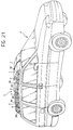
rear locking device 66. - A third embodiment of a transporting system according to the invention will now be described with reference to Figures 19 to 21.
- In the third embodiment also, the system provides for the use of a given maximum number of pairs of containers of specular form.
- In the embodiment shown by way of example, the use of three pairs of containers which are again indicated by the
numbers 1 to 6 is provided for in particular. - In the solution according to Figures 19 to 21, pairs of parallel guides, directed transversely to the longitudinal axis of the roof R, are secured thereto. Figure 19 shows in particular six pairs of guides indicated 101 to 106. These guides advantageously consist of a plastics material with a low coefficient of friction, for example polytetrafluoroethylene (Teflon), preferably of a colour corresponding to that of the bodywork of the motor vehicle M.
- A
strip 70 which forms a hooked retaining member for each of thecontainers 1 to 6 in predetermined positions on the sides is removably secured along the centre line of the roof R. In Figure 19 these hooked members are indicated 71-76. As will be better seen from Figure 20, the hooked members 71-76 extend at a spacing from the surface of the roof R. - In the respective faces to be turned towards the roof R, the
containers 1 to 6 have respective pairs of parallel channels or grooves 81-86 which can engage in a supporting and sliding manner on the associated guides 101-106 applied to this roof. - In the respective faces to be turned towards the longitudinal axis of the roof R, the containers 1-6 have respective recesses 91-96 (Figure 19) which can be coupled firmly to the associated hooked members 71-76 carried by the
strip 70. - As will be described in greater detail below, a locking device which can cooperate with the associated hooked retention member of the
strip 70 is accommodated in the recess of each container. - In the embodiment according to Figures 19 to 21, the
containers 1 to 6 can be individually supported on the associated guides 101-106 installed on the sides of the vehicle and thus very conveniently. Furthermore, as will become clearer from the following, these containers can be individually mounted and removed from the roof, with obvious advantages in terms of convenience and practicality of use. - Figures 20 and 20a show a possible embodiment of the locking device associated with each container, purely by way of example. In the embodiment illustrated, this device comprises a
bolt 97 carried by ashaft 98 which can rotate in abase opening 99 adjacent the base of the container. Theshaft 98 can be actuated in rotation by means of alock cylinder 110 which is accessible on the side face of the container which, in its state of use, is turned towards the body side of the motor vehicle. By means of theshaft 98, thebolt 27 can be placed in an angular position in which it engages the notch in the hooked member to which the container is coupled (hookedmember 73 in Figures 20 and 20a). The engagement of this hooked member in the associated recess in the container prevents the movement of the container in the vertical direction relative to the part. The engagement of thebolt 97 in the notch in the hooked member prevents the container uncoupling from this hooked member. In order to prevent thecontainers 3 jumping and vibrating, they can advantageously be provided with resilient pads on their faces to be turned towards the roof R and towards the adjacent containers. Some of these resilient pads are shown in Figure 20 where they are indicated by thereference numerals - During the operations for coupling and uncoupling the containers 1-6 to and from the associated hooked members 71-76, these containers slide on the associated guides 101-106 without coming into contact with the surface of the roof R, except with their lower
resilient pads 111. Every possibility of the surface of the roof being scratched or cut is thus avoided. - The variant described above with reference to Figures 19 to 21 also enables different configurations of the system, corresponding to different carrying capacities, to be produced.
- Naturally, the principle of the invention remaining the same, the forms of embodiment and details of production can be widely varied with respect to that which has been described and illustrated purely by way of non-limiting example, without, however, departing from the scope of the present invention as defined in the appended Claims.
Claims (15)
- A system for transporting luggage and the like on the roof (R) of a motor vehicle (M), comprising:
retention and guide means (7, 9, 13, 26; 47, 49, 52, 53, 66; 70-76) which can be secured to the roof (R) of the motor vehicle (M); and
a plurality of containers (1-6) which are substantially suitcase-like and can be anchored removably to the retention and guide means; the system being characterized in that it comprises at least one (first) pair of containers (1, 2) which are substantially specular, having a width (L) which is substantially less than or equal to half the width of the roof (R) of the motor vehicle (M) and having a substantially wedge-shaped aerodynamic profile; it being possible to dispose the containers (1, 2) on the roof (R) and anchor them to the retention and guide means adjacent one another, parallel to the transverse sides of the roof (R); and in that the retention and guide means (7, 9, 13, 26; 47, 49, 52, 53, 66; 70-76) are configured so as to define a plurality of successive anchorage positions for the containers (1, 2) in the longitudinal direction of the roof (R) of the motor vehicle (M). - A system according to Claim 1, characterized in that it comprises at least a second pair of containers (5, 6) of specular form, which have a width (L) substantially less than or equal to half the width of the roof (R) and which can be disposed adjacent one another parallel to the transverse sides of the roof (R), adjacent the rear faces of the containers (1, 2) of the first pair, and having a shape such that, contiguously with one another and with the containers (1, 2) of the first pair, they form a volume having a substantially wedge-shaped aerodynamic shape.
- A system according to Claim 2, characterized in that the retention and guide means (7, 9, 13, 26; 47, 49, 52, 53, 66; 70-76) are configured so as to define a plurality of successive anchorage positions in the longitudinal direction of the motor vehicle (M) for the assembly formed by the first and second pairs of containers (1, 2; 5, 6).
- A system according to any one of the preceding claims, characterized in that the containers (1-6) are provided with respective handles (H) on the respective faces which are turned towards the body sides of the motor vehicle (M) in the mounted state on the roof (R).
- A system according to any one of the preceding claims, characterized in that sensor means which can provide electrical signals indicating the presence of the containers (1-6) in the anchorage positions are associated with the retention and guide means (7, 9, 13, 26; 47, 49, 52, 53, 66; 70-76).
- A system according to Claim 5, characterized in that it further comprises optical or acoustic signalling means (40) which can be controlled on the basis of the signals provided by the sensor means, in order to signal the presence of the containers (1-6) in the respective preset anchorage positions.
- A system according to any one of the preceding claims, characterized in that the retention and guide means comprise:
a profiled portion (7) with a substantially H-shaped section, to be secured on the longitudinal centre line of the roof (R) and defining two longitudinal channels or guides (8) in its sides;
a first and second C-shaped profiled portion (9) to be secured along the longitudinal sides of the roof (R) with the respective recesses (10) facing the H-shaped profiled portion (7); and in that each of the containers (1-6) has respective side fins (11) which can engage slidingly a channel or guide (10) of a C-shaped profiled portion (9) and the channel or guide (9) of the H-shaped profiled portion. - A system according to Claim 7, characterized in that at least the channels or guides (8) of the H-shaped profiled portion (7) and/or those (10) of the C-shaped profiled portions (9) at the end facing the front side of the roof (R) are transversely closed in order to stop the containers (1-6) sliding; and it being possible to couple a first locking device (13), which can prevent the containers (1-6) being removed from the profiled portions (7, 9), to the rear end of the H-shaped profiled portion (7).
- A system according to Claim 8, characterized in that it further comprises a second locking device (26) which can be coupled to the H-shaped profiled portion (7) in preset intermediate positions in order to define corresponding abutment limit positions for the first pair of containers (1, 2).
- A system according to any one of Claims 1 to 6, characterized in that the retention and guide means comprise:
a central strip (47) to be secured on the longitudinal centre line of the roof (R) and having on each side a respective groove (50); and
a first and a second side strip (49) to be secured along the longitudinal sides of the roof (R) parallel to the central strip (47) and having a respective groove (51) on each side;
a plurality of first guide elements (52) which are substantially T-shaped and which can be slidingly coupled in the longitudinal side grooves (50) in the central strip (47) and can be locked in an unlockable manner in respective operating positions defined along this strip (47) at distances which are shorter than the lengths of these containers (1-6), in which operating positions the flanges (52a) of the guide elements (52) extend transversely to the central strip (47); and
a first and a second plurality of second guide elements (53) which are substantially L-shaped and have first legs which can be slidingly engaged in the grooves (51) in one of the side strips (49); it being possible to lock the second guide elements (53) in an unlockable manner in respective operating positions defined in the associated side strips (49), at distances which are shorter than the lengths of the containers (1-6), and in which positions their second legs (53b) extend transversely, in the direction of the central strip (47);
the containers (1-6) having respective parallel longitudinal side channels (66, 67) which can be slidingly coupled to the flanges (52a) and respectively to the second legs (53b) of the first and of the second guide elements (52, 53) respectively;
at least one of the first guide elements (52) and/or at least one pair of the second guide elements (53) being configured so as to have stop surfaces for defining front abutment limit positions for the first pair of containers (1, 2). - A system according to Claim 10, characterized in that it further comprises a locking device (66) which can be coupled to the strips (47, 49), in particular to the central strip (47), so as to prevent the removal of the containers (1-6) from the guide elements (52, 53).
- A system according to any one of Claims 1 to 6, characterized in that the retention and guide means comprise:
at least a first and a second group of guides (101-106) to be secured to the roof (R) in respective parallel directions, transversely to the longitudinal axis of the roof (R); and - a plurality of pairs of retention devices (71, 72; 73, 74; 75, 76) to be secured in respective predetermined positions along the longitudinal centre line of the roof (R); and in that, in the respective face to be turned towards the roof (R), the containers (1-6) have respective pluralities of parallel channels or grooves (81-86) which can engage in a supporting and sliding manner on the guides (101-106) of each group of guides, and, in the respective face to be turned towards the longitudinal axis of the roof (R), they comprise a respective locking and coupling device (97, 98) which can be coupled to one of the retention devices (71-76). - A system according to Claim 12, characterized in that the guides (101-106) are made of a plastics material having a low coefficient of friction, in particular of polytetrafluoroethylene.
- A system according to Claim 12 or 13, characterized in that each retention device comprises a hooked member (71-76), and the coupling and locking device of each container (1-6) has a recess (91-96) of the container (1-6) which can accommodate the hooked member (71-76), and in which a movable bolt (97) is mounted which can be actuated from the exterior of the container (1-6) and can engage the hooked member (71-76).
- A system according to Claim 14, characterized in that the bolt (97) is carried by a shaft (98) which is rotatably supported adjacent the wall of the container (1-6) facing the roof (R) of the motor vehicle in use, and which can be actuated in rotation by means of a lock (110) disposed on the side face of the container (1-6) which, in use, is turned towards the motor vehicle body side.
Applications Claiming Priority (2)
| Application Number | Priority Date | Filing Date | Title |
|---|---|---|---|
| IT94TO001060A IT1268406B1 (en) | 1994-12-22 | 1994-12-22 | MODULAR SYSTEM FOR THE TRANSPORT OF LUGGAGE AND SIMILAR ON THE ROOF OF A MOTOR VEHICLE. |
| ITTO941060 | 1994-12-22 |
Publications (2)
| Publication Number | Publication Date |
|---|---|
| EP0718155A1 true EP0718155A1 (en) | 1996-06-26 |
| EP0718155B1 EP0718155B1 (en) | 2000-03-22 |
Family
ID=11412999
Family Applications (1)
| Application Number | Title | Priority Date | Filing Date |
|---|---|---|---|
| EP95120084A Expired - Lifetime EP0718155B1 (en) | 1994-12-22 | 1995-12-19 | Modular system for transporting luggage on the roof of a motor vehicle |
Country Status (3)
| Country | Link |
|---|---|
| EP (1) | EP0718155B1 (en) |
| DE (1) | DE69515825T2 (en) |
| IT (1) | IT1268406B1 (en) |
Cited By (9)
| Publication number | Priority date | Publication date | Assignee | Title |
|---|---|---|---|---|
| EP0850805A1 (en) | 1996-12-23 | 1998-07-01 | FIAT AUTO S.p.A. | A support structure of a system for transporting luggage and the like on the roof of a motor vehicle |
| GB2341367A (en) * | 1998-09-10 | 2000-03-15 | Dennis Smith | Luggage carrying system |
| DE10234572B4 (en) * | 2002-07-30 | 2006-03-02 | Webasto Ag | Fastening device for a roof rack |
| WO2009083068A1 (en) * | 2007-12-21 | 2009-07-09 | Gm Global Technology Operations, Inc. | Motor vehicle having a carrier system and theft alert system |
| WO2014015919A1 (en) * | 2012-07-25 | 2014-01-30 | Audi Ag | Roof rack assembly for a motor vehicle |
| US9156398B2 (en) | 2012-08-24 | 2015-10-13 | GM Global Technology Operations LLC | Method for operating a motor vehicle and motor vehicle |
| WO2016120687A2 (en) | 2014-11-12 | 2016-08-04 | PEREYRA, Ivana Andrea | Retaining and fastening means to a top railing placed on a vehicle´s roof, for at least one modular selectively removable platform, carrier of a generic object |
| WO2017029204A1 (en) * | 2015-08-18 | 2017-02-23 | Matthias Pleyer | Holding device for a vehicle roof load |
| EP3587188A1 (en) * | 2018-06-27 | 2020-01-01 | VDL Hapro B.V. | Roof box with locking system |
Families Citing this family (1)
| Publication number | Priority date | Publication date | Assignee | Title |
|---|---|---|---|---|
| DE102023105889A1 (en) * | 2023-03-09 | 2024-09-12 | Phänomen Robur Beteiligungs UG (haftungsbeschränkt) | Roof box for solar-electric energy generation |
Citations (8)
| Publication number | Priority date | Publication date | Assignee | Title |
|---|---|---|---|---|
| FR2445246A1 (en) * | 1978-12-29 | 1980-07-25 | Froger Michel | Luggage container fitted to car roof - comprises two half shells which slide to and from each other over base and are sealed and locked in closed position |
| FR2484221A1 (en) * | 1980-04-15 | 1981-12-18 | Eymard Jean Louis | Set of suitcases which are superposed - have bevelled lateral faces and are closed by base plate with concealed lock |
| FR2581943A1 (en) * | 1985-02-11 | 1986-11-21 | Berte Xavier | Set of aerodynamic suitcases |
| DE3546220A1 (en) * | 1985-12-27 | 1987-07-02 | Dietmar Herwig | Transporting device for motor vehicles |
| DE8804776U1 (en) * | 1988-04-12 | 1989-08-10 | Reuss, Peter | Roof racks, especially for passenger cars |
| US4955519A (en) * | 1989-03-24 | 1990-09-11 | Forrester Keith E | Ski case sled |
| DE3937244C1 (en) * | 1989-11-09 | 1991-04-11 | Jetbag Gmbh, 8430 Neumarkt, De | Luggage case mounted on car roof in place of rack - has internal battery-driven siren reacting before case is actually opened |
| DE9207442U1 (en) * | 1992-06-02 | 1992-10-08 | HS Technik und Design Technische Entwicklungen GmbH, 8031 Oberpfaffenhofen | Insertable roof that can be inserted into a roof opening of a passenger car |
-
1994
- 1994-12-22 IT IT94TO001060A patent/IT1268406B1/en active IP Right Grant
-
1995
- 1995-12-19 EP EP95120084A patent/EP0718155B1/en not_active Expired - Lifetime
- 1995-12-19 DE DE69515825T patent/DE69515825T2/en not_active Expired - Fee Related
Patent Citations (8)
| Publication number | Priority date | Publication date | Assignee | Title |
|---|---|---|---|---|
| FR2445246A1 (en) * | 1978-12-29 | 1980-07-25 | Froger Michel | Luggage container fitted to car roof - comprises two half shells which slide to and from each other over base and are sealed and locked in closed position |
| FR2484221A1 (en) * | 1980-04-15 | 1981-12-18 | Eymard Jean Louis | Set of suitcases which are superposed - have bevelled lateral faces and are closed by base plate with concealed lock |
| FR2581943A1 (en) * | 1985-02-11 | 1986-11-21 | Berte Xavier | Set of aerodynamic suitcases |
| DE3546220A1 (en) * | 1985-12-27 | 1987-07-02 | Dietmar Herwig | Transporting device for motor vehicles |
| DE8804776U1 (en) * | 1988-04-12 | 1989-08-10 | Reuss, Peter | Roof racks, especially for passenger cars |
| US4955519A (en) * | 1989-03-24 | 1990-09-11 | Forrester Keith E | Ski case sled |
| DE3937244C1 (en) * | 1989-11-09 | 1991-04-11 | Jetbag Gmbh, 8430 Neumarkt, De | Luggage case mounted on car roof in place of rack - has internal battery-driven siren reacting before case is actually opened |
| DE9207442U1 (en) * | 1992-06-02 | 1992-10-08 | HS Technik und Design Technische Entwicklungen GmbH, 8031 Oberpfaffenhofen | Insertable roof that can be inserted into a roof opening of a passenger car |
Cited By (17)
| Publication number | Priority date | Publication date | Assignee | Title |
|---|---|---|---|---|
| EP0850805A1 (en) | 1996-12-23 | 1998-07-01 | FIAT AUTO S.p.A. | A support structure of a system for transporting luggage and the like on the roof of a motor vehicle |
| GB2341367A (en) * | 1998-09-10 | 2000-03-15 | Dennis Smith | Luggage carrying system |
| GB2341367B (en) * | 1998-09-10 | 2002-04-10 | Dennis Smith | Luggage carrying and transport system |
| DE10234572B4 (en) * | 2002-07-30 | 2006-03-02 | Webasto Ag | Fastening device for a roof rack |
| WO2009083068A1 (en) * | 2007-12-21 | 2009-07-09 | Gm Global Technology Operations, Inc. | Motor vehicle having a carrier system and theft alert system |
| GB2467720A (en) * | 2007-12-21 | 2010-08-11 | Gm Global Tech Operations Inc | Motor vehicle having a carrier system and theft alert system |
| GB2467720B (en) * | 2007-12-21 | 2012-06-27 | Gm Global Tech Operations Inc | A motor vehicle with a carrier system and an anti-theft alarm system |
| CN104487290A (en) * | 2012-07-25 | 2015-04-01 | 奥迪股份公司 | Roof rack assembly for a motor vehicle |
| WO2014015919A1 (en) * | 2012-07-25 | 2014-01-30 | Audi Ag | Roof rack assembly for a motor vehicle |
| CN104487290B (en) * | 2012-07-25 | 2016-09-14 | 奥迪股份公司 | Roof support device for motor vehicles |
| US9156398B2 (en) | 2012-08-24 | 2015-10-13 | GM Global Technology Operations LLC | Method for operating a motor vehicle and motor vehicle |
| WO2016120687A2 (en) | 2014-11-12 | 2016-08-04 | PEREYRA, Ivana Andrea | Retaining and fastening means to a top railing placed on a vehicle´s roof, for at least one modular selectively removable platform, carrier of a generic object |
| US10053021B2 (en) | 2014-11-12 | 2018-08-21 | Raul Amaldo Cabiche | Vehicle-top object carrier |
| WO2017029204A1 (en) * | 2015-08-18 | 2017-02-23 | Matthias Pleyer | Holding device for a vehicle roof load |
| EP3587188A1 (en) * | 2018-06-27 | 2020-01-01 | VDL Hapro B.V. | Roof box with locking system |
| NL2021189B1 (en) * | 2018-06-27 | 2020-01-06 | Vdl Hapro B V | Roof box |
| EP4140819A1 (en) * | 2018-06-27 | 2023-03-01 | VDL Hapro B.V. | Roof box |
Also Published As
| Publication number | Publication date |
|---|---|
| ITTO941060A0 (en) | 1994-12-22 |
| EP0718155B1 (en) | 2000-03-22 |
| ITTO941060A1 (en) | 1996-06-22 |
| IT1268406B1 (en) | 1997-02-27 |
| DE69515825D1 (en) | 2000-04-27 |
| DE69515825T2 (en) | 2000-11-30 |
Similar Documents
| Publication | Publication Date | Title |
|---|---|---|
| US5547242A (en) | Latch/unlatch indicator for vehicle seat-to floor latch mechanism | |
| EP0718155A1 (en) | Modular system for transporting luggage on the roof of a motor vehicle | |
| EP0483141B1 (en) | An antitheft pedal-locking device for vehicles | |
| US6655561B2 (en) | Device comprising a removable sliding central console | |
| EP0301828A2 (en) | Baby carriage | |
| GB2321850A (en) | Child safety seat | |
| US4735350A (en) | Roof carrier structure for a vehicular automobile and a lock therefor | |
| US6158639A (en) | Article carrier for vehicle | |
| US5529259A (en) | Seat belt retraction mechanism | |
| CN214117874U (en) | Car sliding door and car | |
| JPS63162347A (en) | Seat for automobile | |
| JPS62194955A (en) | Console box for automobile | |
| US4730845A (en) | Anchoring device for a slidable unit, comprising a tongue, in particular for a passive safety belt device | |
| JPH0635769Y2 (en) | Seat slide device | |
| JPH0738008Y2 (en) | Vehicle luggage rack case | |
| JP3191624B2 (en) | Luggage cover device | |
| JP3690755B2 (en) | Drawer lock device in furniture | |
| JPH0414276Y2 (en) | ||
| KR200195862Y1 (en) | A sliding element for supporting things in an automobile | |
| JPS5835544Y2 (en) | Automobile seat slide device | |
| KR100457911B1 (en) | A moving console of an automobile | |
| KR100230194B1 (en) | Glove box lock structure of car | |
| KR100353939B1 (en) | Rear floor | |
| JPH0247076Y2 (en) | ||
| JP2558796Y2 (en) | Accessory storage device for vehicles |
Legal Events
| Date | Code | Title | Description |
|---|---|---|---|
| PUAI | Public reference made under article 153(3) epc to a published international application that has entered the european phase |
Free format text: ORIGINAL CODE: 0009012 |
|
| AK | Designated contracting states |
Kind code of ref document: A1 Designated state(s): DE ES FR GB SE |
|
| 17P | Request for examination filed |
Effective date: 19961109 |
|
| 17Q | First examination report despatched |
Effective date: 19980417 |
|
| GRAG | Despatch of communication of intention to grant |
Free format text: ORIGINAL CODE: EPIDOS AGRA |
|
| GRAG | Despatch of communication of intention to grant |
Free format text: ORIGINAL CODE: EPIDOS AGRA |
|
| GRAH | Despatch of communication of intention to grant a patent |
Free format text: ORIGINAL CODE: EPIDOS IGRA |
|
| GRAH | Despatch of communication of intention to grant a patent |
Free format text: ORIGINAL CODE: EPIDOS IGRA |
|
| GRAA | (expected) grant |
Free format text: ORIGINAL CODE: 0009210 |
|
| AK | Designated contracting states |
Kind code of ref document: B1 Designated state(s): DE ES FR GB SE |
|
| PG25 | Lapsed in a contracting state [announced via postgrant information from national office to epo] |
Ref country code: SE Free format text: THE PATENT HAS BEEN ANNULLED BY A DECISION OF A NATIONAL AUTHORITY Effective date: 20000322 Ref country code: ES Free format text: THE PATENT HAS BEEN ANNULLED BY A DECISION OF A NATIONAL AUTHORITY Effective date: 20000322 |
|
| REF | Corresponds to: |
Ref document number: 69515825 Country of ref document: DE Date of ref document: 20000427 |
|
| ET | Fr: translation filed | ||
| PLBE | No opposition filed within time limit |
Free format text: ORIGINAL CODE: 0009261 |
|
| STAA | Information on the status of an ep patent application or granted ep patent |
Free format text: STATUS: NO OPPOSITION FILED WITHIN TIME LIMIT |
|
| 26N | No opposition filed | ||
| REG | Reference to a national code |
Ref country code: GB Ref legal event code: IF02 |
|
| PGFP | Annual fee paid to national office [announced via postgrant information from national office to epo] |
Ref country code: DE Payment date: 20081128 Year of fee payment: 14 |
|
| PGFP | Annual fee paid to national office [announced via postgrant information from national office to epo] |
Ref country code: GB Payment date: 20081120 Year of fee payment: 14 |
|
| PGFP | Annual fee paid to national office [announced via postgrant information from national office to epo] |
Ref country code: FR Payment date: 20081231 Year of fee payment: 14 |
|
| GBPC | Gb: european patent ceased through non-payment of renewal fee |
Effective date: 20091219 |
|
| REG | Reference to a national code |
Ref country code: FR Ref legal event code: ST Effective date: 20100831 |
|
| PG25 | Lapsed in a contracting state [announced via postgrant information from national office to epo] |
Ref country code: FR Free format text: LAPSE BECAUSE OF NON-PAYMENT OF DUE FEES Effective date: 20091231 |
|
| PG25 | Lapsed in a contracting state [announced via postgrant information from national office to epo] |
Ref country code: DE Free format text: LAPSE BECAUSE OF NON-PAYMENT OF DUE FEES Effective date: 20100701 |
|
| PG25 | Lapsed in a contracting state [announced via postgrant information from national office to epo] |
Ref country code: GB Free format text: LAPSE BECAUSE OF NON-PAYMENT OF DUE FEES Effective date: 20091219 |