EP0718563A1 - Valve pour installations de chauffage, de production d'eau chaude ou de réfrigération - Google Patents
Valve pour installations de chauffage, de production d'eau chaude ou de réfrigération Download PDFInfo
- Publication number
- EP0718563A1 EP0718563A1 EP95119282A EP95119282A EP0718563A1 EP 0718563 A1 EP0718563 A1 EP 0718563A1 EP 95119282 A EP95119282 A EP 95119282A EP 95119282 A EP95119282 A EP 95119282A EP 0718563 A1 EP0718563 A1 EP 0718563A1
- Authority
- EP
- European Patent Office
- Prior art keywords
- valve
- spindle
- closure piece
- hollow
- housing
- Prior art date
- Legal status (The legal status is an assumption and is not a legal conclusion. Google has not performed a legal analysis and makes no representation as to the accuracy of the status listed.)
- Granted
Links
Images
Classifications
-
- G—PHYSICS
- G05—CONTROLLING; REGULATING
- G05D—SYSTEMS FOR CONTROLLING OR REGULATING NON-ELECTRIC VARIABLES
- G05D23/00—Control of temperature
- G05D23/01—Control of temperature without auxiliary power
- G05D23/02—Control of temperature without auxiliary power with sensing element expanding and contracting in response to changes of temperature
- G05D23/021—Control of temperature without auxiliary power with sensing element expanding and contracting in response to changes of temperature the sensing element being a non-metallic solid, e.g. elastomer, paste
- G05D23/023—Control of temperature without auxiliary power with sensing element expanding and contracting in response to changes of temperature the sensing element being a non-metallic solid, e.g. elastomer, paste the sensing element being placed outside a regulating fluid flow
-
- F—MECHANICAL ENGINEERING; LIGHTING; HEATING; WEAPONS; BLASTING
- F24—HEATING; RANGES; VENTILATING
- F24D—DOMESTIC- OR SPACE-HEATING SYSTEMS, e.g. CENTRAL HEATING SYSTEMS; DOMESTIC HOT-WATER SUPPLY SYSTEMS; ELEMENTS OR COMPONENTS THEREFOR
- F24D19/00—Details
- F24D19/08—Arrangements for drainage, venting or aerating
- F24D19/082—Arrangements for drainage, venting or aerating for water heating systems
- F24D19/088—Draining arrangements
Definitions
- the invention relates to a valve for heating, hot water or cooling systems, in which on a housing a connection support to the strand, a connection piece to the consumer and a screw connection for receiving a valve upper part with a arranged on a hollow valve stem first closure piece, which with a valve seat in Housing forms a throttle-like presetting for the flow, are provided and in the hollow valve spindle there is a second hollow which can be actuated from the outside against the pressure of a spring: double-acting valve closure piece can be displaced from the outside in relation to a corresponding valve seat in the valve spindle in order to empty a line via the valve spindle, wherein this second valve closure piece is displaceable with its end opposite the drain valve seat through the first valve closure piece in the direction of the housing valve seat.
- Such a valve for a heating system is known from DE-OS 41 06 278. These heating valves can be combined with a pressure regulator. These valves have an emptying function, they can be used as a shut-off valve and have a pre-setting option without the valve housing or the upper part having to be removed. When combined with a pressure regulator, this regulator engages with a corresponding actuator in the hollow valve spindle and acts against the second closure piece.
- the object of the invention is to control a generic valve for heating, hot water or cooling systems also temperature controlled.
- the generic valve can be equipped with a thermostat controller without dismantling the upper part, so that this valve can be used for temperature control in the respective systems. Together with a corresponding upper part, the thermostat can be used on the assembled housing at any time.
- valve spindle With claim 7 a structurally favorable design of the valve spindle is characterized, which shows the assembly effort of such a generic valve.
- the invention is explained in more detail below with reference to an illustrated embodiment.
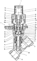
- the illustration shows a longitudinal section through a heating valve, on which a thermostat is arranged in the open position.
- the number 1 in the figure denotes the housing of a heating valve. On this housing opposite the connecting pieces 11 and 12 are indicated, which lead to the strand or to the radiator (consumer).
- the obliquely directed screw socket 13 serves to receive the screwed-in valve upper part 2.
- a valve seat 14 is formed in the interior of the housing 1, against which a first closure piece 4 arranged on the hollow valve spindle 3 acts. In principle, the position of this first closure piece 4 relative to the corresponding valve seat 14 determines the presetting for the flow. With this first closure piece 4, the heating valve can be shut off.
- the hollow valve spindle designated overall by the number 3, is formed in two parts.
- the lower spindle section 3b is inserted into the upper spindle section 3a and held with a snap or snap connection.
- a snap ring 10 engages in the groove 34 on the upper spindle section 3a and in the opposite groove 55 on the lower spindle section 3b.
- An elastic flat seal 33 for example made of an elastomer, is inserted in a shoulder 31a in the interior of the upper spindle section 3a. With pretension when the snap or snap connection 34, 10, 55 engages, the lower spindle section 3b engages with its end face sealingly in this flat seal 33, which in turn secures the snap or snap connection in the axial direction due to its elastic restoring force.
- This flat seal 33 protrudes into the interior of the two hollow spindle sections 3a, 3b.
- a second closure piece 5 can be displaced from the outside against the pressure of a return spring 6.
- This return spring 6 is supported at one end in the interior of the lower spindle section 3b.
- This second closure piece is double-acting. In a corresponding position due to the return spring 6, the upper end 51 of the closure piece acts against the inwardly projecting flat seal 33.
- the opposite breech end 52 of the second breech 5 protrudes through the lower spindle section 3b and forms with the protruding section the contour of the first breech 4 and determines the throttle gap with it.
- An inserted, not shown emptying device acts through the cavity 31 of the upper valve stem portion 3a on the upper closure end 51. After lifting off the second closure piece 5 with its upper closure end 51 and the circumferential groove 54 formed thereon from the flat seal 33, water flows out of the Strand or the radiator through the hollow valve stem to the outside.
- a screw cap 8 is rotatably fitted on a rotary drive.
- the presetting is carried out after removing the screw cap 8.
- the valve spindle 3 is not moved. This is followed by a corresponding rotation of the display device designated overall by the number 7.
- the thermostat regulator designated as a whole by the number 9, is placed on the hollow valve spindle 3.
- the threaded connector 92 provided on the housing 91 is screwed onto the external thread section 32 of the upper spindle section 3a in a sealed manner.
- an expansion element 93 is received, which is displaceable against an overtravel spring 94.
- the overtravel spring 94 acts alone, the expansion element 93 rests on the valve spindle 3 with a collar 97.
- the piston 95 of the expansion element 93 protrudes into the hollow valve spindle 3 or its upper spindle section 3a and acts against a cylindrical, hollow actuating member 111, which in turn bears with its open end 111b against the second closure piece 5.
- the upper closed end 111a of this actuator 111 is guided to a limited extent in a limiting sleeve 98 which is fixed on the expansion element 93.
- the lower end 98a of this limiting sleeve is retracted inwards, so that in the end position the actuating member 111 strikes against this retracted end 98a with an outer collar at the closed end 111a.
- the actuator 111 is guided in a plastic sliding bush 36 and sealed with the ring seals 111c.
- the plastic sliding bush 36 is inserted flush into a shoulder 35 in the interior of the upper spindle section 3a.
- thermostat housing 91 Water penetrating through the cavity 53 in the second closure piece 5 enters the actuating element 111 and heats the expansion element 93 via the piston 95, which element lifts off against the stroke of the spring 94.
- the thermostat housing 91 is surrounded by a jacket 96. The distance of the first closure piece 4 from the valve seat 14 on the housing is determined via the thermostat controller 9.
- the expansion element 93 When the housing 91 of the thermostat 9 is screwed on, the expansion element 93 rests with its collar 97 on the upper valve spindle section 3a. This enables precise adjustment between the contact edge and the end of the actuator 111. In the screwed-on state, the expansion element 93 pushes slightly in the direction of the overtravel spring 94, so that manufacturing and screw-on tolerances of the housing 91 have no influence on the temperature adjustment.
- valve shown can be used in the same way for hot water or cooling systems, the line leading to the consumer in a cooling system leading to the heat exchanger and in a hot water system leading to the hot water generator.
Landscapes
- Engineering & Computer Science (AREA)
- Physics & Mathematics (AREA)
- Chemical & Material Sciences (AREA)
- General Physics & Mathematics (AREA)
- Automation & Control Theory (AREA)
- Thermal Sciences (AREA)
- Fluid Mechanics (AREA)
- Combustion & Propulsion (AREA)
- Mechanical Engineering (AREA)
- General Engineering & Computer Science (AREA)
- Sorption Type Refrigeration Machines (AREA)
- Devices That Are Associated With Refrigeration Equipment (AREA)
- Temperature-Responsive Valves (AREA)
Applications Claiming Priority (2)
| Application Number | Priority Date | Filing Date | Title |
|---|---|---|---|
| DE9420412U DE9420412U1 (de) | 1994-12-21 | 1994-12-21 | Ventil für Heizungs-, Warmwasser- oder Kühlanlagen |
| DE9420412U | 1994-12-21 |
Publications (2)
| Publication Number | Publication Date |
|---|---|
| EP0718563A1 true EP0718563A1 (fr) | 1996-06-26 |
| EP0718563B1 EP0718563B1 (fr) | 1999-05-19 |
Family
ID=6917687
Family Applications (1)
| Application Number | Title | Priority Date | Filing Date |
|---|---|---|---|
| EP95119282A Expired - Lifetime EP0718563B1 (fr) | 1994-12-21 | 1995-12-07 | Valve pour installations de chauffage, de production d'eau chaude ou de réfrigération |
Country Status (4)
| Country | Link |
|---|---|
| EP (1) | EP0718563B1 (fr) |
| AT (1) | ATE180324T1 (fr) |
| DE (2) | DE9420412U1 (fr) |
| DK (1) | DK0718563T3 (fr) |
Cited By (2)
| Publication number | Priority date | Publication date | Assignee | Title |
|---|---|---|---|---|
| WO2000006931A1 (fr) * | 1998-07-29 | 2000-02-10 | Honeywell Ag | Valve destinee a des installations a eau chaude |
| AT502342B1 (de) * | 2005-08-16 | 2008-06-15 | F W Oventrop Gmbh & Co Kg | Ventil |
Families Citing this family (5)
| Publication number | Priority date | Publication date | Assignee | Title |
|---|---|---|---|---|
| DE29924249U1 (de) | 1998-07-29 | 2002-08-08 | Honeywell Ag, 63067 Offenbach | Ventil für Warmwasseranlagen |
| DE10056715C5 (de) * | 2000-11-15 | 2008-03-06 | F.W. Oventrop Gmbh & Co. Kg | Ventil für Warmwasseranlagen |
| DE102006059577B4 (de) * | 2005-08-16 | 2014-05-28 | F.W. Oventrop Gmbh & Co. Kg | Ventil |
| DE102013106046A1 (de) * | 2013-06-11 | 2014-12-11 | Jürgen Schlösser Armaturen GmbH | Ventilanordnung |
| CN116315256B (zh) * | 2023-02-16 | 2026-03-10 | 浙江汇丰汽车零部件股份有限公司 | 一种电动汽车电池冷却器结构、装配工装及其装配方法 |
Citations (2)
| Publication number | Priority date | Publication date | Assignee | Title |
|---|---|---|---|---|
| DE4106278A1 (de) * | 1991-02-28 | 1992-09-03 | Neheim Goeke & Co Metall | Heizungsventil |
| DE9404344U1 (de) * | 1994-02-07 | 1994-06-09 | Gampper Gmbh, 67821 Alsenz | Thermostatventil mit Voreinstellung der Durchflußmenge |
-
1994
- 1994-12-21 DE DE9420412U patent/DE9420412U1/de not_active Expired - Lifetime
-
1995
- 1995-12-07 AT AT95119282T patent/ATE180324T1/de active
- 1995-12-07 DE DE59505971T patent/DE59505971D1/de not_active Expired - Lifetime
- 1995-12-07 EP EP95119282A patent/EP0718563B1/fr not_active Expired - Lifetime
- 1995-12-07 DK DK95119282T patent/DK0718563T3/da active
Patent Citations (2)
| Publication number | Priority date | Publication date | Assignee | Title |
|---|---|---|---|---|
| DE4106278A1 (de) * | 1991-02-28 | 1992-09-03 | Neheim Goeke & Co Metall | Heizungsventil |
| DE9404344U1 (de) * | 1994-02-07 | 1994-06-09 | Gampper Gmbh, 67821 Alsenz | Thermostatventil mit Voreinstellung der Durchflußmenge |
Cited By (3)
| Publication number | Priority date | Publication date | Assignee | Title |
|---|---|---|---|---|
| WO2000006931A1 (fr) * | 1998-07-29 | 2000-02-10 | Honeywell Ag | Valve destinee a des installations a eau chaude |
| AT502342B1 (de) * | 2005-08-16 | 2008-06-15 | F W Oventrop Gmbh & Co Kg | Ventil |
| NL1032323C2 (nl) * | 2005-08-16 | 2008-08-27 | F W Oventrop Gmbh & Co Kg | Klep. |
Also Published As
| Publication number | Publication date |
|---|---|
| DK0718563T3 (da) | 1999-11-29 |
| EP0718563B1 (fr) | 1999-05-19 |
| DE9420412U1 (de) | 1995-02-16 |
| ATE180324T1 (de) | 1999-06-15 |
| DE59505971D1 (de) | 1999-06-24 |
Similar Documents
| Publication | Publication Date | Title |
|---|---|---|
| DE19620694C2 (de) | Ventilanordnung | |
| DE19834151C1 (de) | Ventil für Warmwasseranlagen | |
| EP0691494A1 (fr) | Valve sanitaire | |
| EP0553224A1 (fr) | Soupape a haute pression. | |
| DE29823960U1 (de) | Ventil für Warmwasseranlagen | |
| DE68903791T2 (de) | Ventil-uebersteuerungsmechanismus. | |
| DE2628253A1 (de) | Ventil | |
| EP0718563B1 (fr) | Valve pour installations de chauffage, de production d'eau chaude ou de réfrigération | |
| DE102008010347A1 (de) | Verteilerventil mit integrierter Durchflussmesseinrichtung | |
| DE10354192B4 (de) | Heizkörperventil | |
| DE69528986T2 (de) | Kraftstoffregelvorrichtung, teile einer solchen vorrichtung und verfahren zu deren herstellung | |
| EP1212563A1 (fr) | Soupape a encastrer pour un radiateur a elements multiples | |
| DE8134876U1 (de) | Handsteuervorrichtung fuer einen zentralheizungshahn | |
| EP0792433B1 (fr) | Soupape pour installations de chauffage, d'eau chaude ou de refroidissement | |
| DE102005060120A1 (de) | Heizkörper-Einbauventil | |
| DE102004025465A1 (de) | Durchflussmengenregler | |
| DE60119258T2 (de) | Ventil zur Regelung der Strömungsgschwindigkeit eines Fluids für einen Plattenheizkörper oder dergleichen | |
| WO1992015825A1 (fr) | Vanne de radiateur | |
| DE2435328C3 (de) | Heizkörperverschraubung | |
| DE19636410B4 (de) | Armatur für Wasserleitungen | |
| DE2642641C3 (de) | Vorläufige Schutzkappe zur Anbringung an einem Absperrventil | |
| DE1500275A1 (de) | Hochdruckkegelventil | |
| DE69612793T2 (de) | Elastischer Ventilhandgriff | |
| DE202023100855U1 (de) | Anordnung zur Steuerung der Temperatur in einem Trinkwassererwärmer | |
| DE2818481C2 (de) | Mischeinrichtung für eine Handbrause |
Legal Events
| Date | Code | Title | Description |
|---|---|---|---|
| PUAI | Public reference made under article 153(3) epc to a published international application that has entered the european phase |
Free format text: ORIGINAL CODE: 0009012 |
|
| AK | Designated contracting states |
Kind code of ref document: A1 Designated state(s): AT BE DE DK FR GB IT NL SE |
|
| 17P | Request for examination filed |
Effective date: 19961216 |
|
| GRAG | Despatch of communication of intention to grant |
Free format text: ORIGINAL CODE: EPIDOS AGRA |
|
| 17Q | First examination report despatched |
Effective date: 19980515 |
|
| GRAG | Despatch of communication of intention to grant |
Free format text: ORIGINAL CODE: EPIDOS AGRA |
|
| GRAH | Despatch of communication of intention to grant a patent |
Free format text: ORIGINAL CODE: EPIDOS IGRA |
|
| GRAH | Despatch of communication of intention to grant a patent |
Free format text: ORIGINAL CODE: EPIDOS IGRA |
|
| GRAA | (expected) grant |
Free format text: ORIGINAL CODE: 0009210 |
|
| RAP1 | Party data changed (applicant data changed or rights of an application transferred) |
Owner name: METALLWERKE NEHEIM GOEKE & CO. GMBH |
|
| AK | Designated contracting states |
Kind code of ref document: B1 Designated state(s): AT BE DE DK FR GB IT NL SE |
|
| REF | Corresponds to: |
Ref document number: 180324 Country of ref document: AT Date of ref document: 19990615 Kind code of ref document: T |
|
| REF | Corresponds to: |
Ref document number: 59505971 Country of ref document: DE Date of ref document: 19990624 |
|
| ET | Fr: translation filed | ||
| GBT | Gb: translation of ep patent filed (gb section 77(6)(a)/1977) |
Effective date: 19990721 |
|
| REG | Reference to a national code |
Ref country code: DK Ref legal event code: T3 |
|
| PLBE | No opposition filed within time limit |
Free format text: ORIGINAL CODE: 0009261 |
|
| STAA | Information on the status of an ep patent application or granted ep patent |
Free format text: STATUS: NO OPPOSITION FILED WITHIN TIME LIMIT |
|
| 26N | No opposition filed | ||
| REG | Reference to a national code |
Ref country code: GB Ref legal event code: IF02 |
|
| NLS | Nl: assignments of ep-patents |
Owner name: HONEYWELL TECHNOLOGIES SARL Owner name: HONEYWELL AG |
|
| NLT1 | Nl: modifications of names registered in virtue of documents presented to the patent office pursuant to art. 16 a, paragraph 1 |
Owner name: HONEYWELL GMBH |
|
| REG | Reference to a national code |
Ref country code: GB Ref legal event code: 732E |
|
| REG | Reference to a national code |
Ref country code: FR Ref legal event code: TP |
|
| REG | Reference to a national code |
Ref country code: FR Ref legal event code: TP |
|
| BECA | Be: change of holder's address |
Owner name: HONEYWELL TECHNOLOGIES SARLAVENUE DE LA GOTTAZ 34- Effective date: 20071219 |
|
| BECH | Be: change of holder |
Owner name: HONEYWELL TECHNOLOGIES SARL Effective date: 20071219 |
|
| PGFP | Annual fee paid to national office [announced via postgrant information from national office to epo] |
Ref country code: AT Payment date: 20101122 Year of fee payment: 16 |
|
| PGFP | Annual fee paid to national office [announced via postgrant information from national office to epo] |
Ref country code: IT Payment date: 20101218 Year of fee payment: 16 |
|
| PGFP | Annual fee paid to national office [announced via postgrant information from national office to epo] |
Ref country code: BE Payment date: 20101213 Year of fee payment: 16 |
|
| BERE | Be: lapsed |
Owner name: HONEYWELL TECHNOLOGIES SARL Effective date: 20111231 |
|
| PG25 | Lapsed in a contracting state [announced via postgrant information from national office to epo] |
Ref country code: BE Free format text: LAPSE BECAUSE OF NON-PAYMENT OF DUE FEES Effective date: 20111231 |
|
| PG25 | Lapsed in a contracting state [announced via postgrant information from national office to epo] |
Ref country code: IT Free format text: LAPSE BECAUSE OF NON-PAYMENT OF DUE FEES Effective date: 20111207 |
|
| REG | Reference to a national code |
Ref country code: AT Ref legal event code: MM01 Ref document number: 180324 Country of ref document: AT Kind code of ref document: T Effective date: 20111207 |
|
| PGFP | Annual fee paid to national office [announced via postgrant information from national office to epo] |
Ref country code: DK Payment date: 20121128 Year of fee payment: 18 |
|
| PG25 | Lapsed in a contracting state [announced via postgrant information from national office to epo] |
Ref country code: AT Free format text: LAPSE BECAUSE OF NON-PAYMENT OF DUE FEES Effective date: 20111207 |
|
| PGFP | Annual fee paid to national office [announced via postgrant information from national office to epo] |
Ref country code: SE Payment date: 20121128 Year of fee payment: 18 Ref country code: GB Payment date: 20121128 Year of fee payment: 18 |
|
| PGFP | Annual fee paid to national office [announced via postgrant information from national office to epo] |
Ref country code: FR Payment date: 20121219 Year of fee payment: 18 Ref country code: NL Payment date: 20121212 Year of fee payment: 18 |
|
| PGFP | Annual fee paid to national office [announced via postgrant information from national office to epo] |
Ref country code: DE Payment date: 20121221 Year of fee payment: 18 |
|
| REG | Reference to a national code |
Ref country code: DE Ref legal event code: R119 Ref document number: 59505971 Country of ref document: DE |
|
| REG | Reference to a national code |
Ref country code: DK Ref legal event code: EBP Effective date: 20131231 |
|
| REG | Reference to a national code |
Ref country code: NL Ref legal event code: V1 Effective date: 20140701 |
|
| REG | Reference to a national code |
Ref country code: SE Ref legal event code: EUG |
|
| GBPC | Gb: european patent ceased through non-payment of renewal fee |
Effective date: 20131207 |
|
| PG25 | Lapsed in a contracting state [announced via postgrant information from national office to epo] |
Ref country code: SE Free format text: LAPSE BECAUSE OF NON-PAYMENT OF DUE FEES Effective date: 20131208 |
|
| REG | Reference to a national code |
Ref country code: FR Ref legal event code: ST Effective date: 20140829 |
|
| REG | Reference to a national code |
Ref country code: DE Ref legal event code: R119 Ref document number: 59505971 Country of ref document: DE Effective date: 20140701 |
|
| PG25 | Lapsed in a contracting state [announced via postgrant information from national office to epo] |
Ref country code: DE Free format text: LAPSE BECAUSE OF NON-PAYMENT OF DUE FEES Effective date: 20140701 Ref country code: NL Free format text: LAPSE BECAUSE OF NON-PAYMENT OF DUE FEES Effective date: 20140701 |
|
| PG25 | Lapsed in a contracting state [announced via postgrant information from national office to epo] |
Ref country code: FR Free format text: LAPSE BECAUSE OF NON-PAYMENT OF DUE FEES Effective date: 20131231 Ref country code: GB Free format text: LAPSE BECAUSE OF NON-PAYMENT OF DUE FEES Effective date: 20131207 |
|
| PG25 | Lapsed in a contracting state [announced via postgrant information from national office to epo] |
Ref country code: DK Free format text: LAPSE BECAUSE OF NON-PAYMENT OF DUE FEES Effective date: 20131231 |