EP0718960A1 - Mehrphasiger vielpoliger Schnittmotor - Google Patents
Mehrphasiger vielpoliger Schnittmotor Download PDFInfo
- Publication number
- EP0718960A1 EP0718960A1 EP94810717A EP94810717A EP0718960A1 EP 0718960 A1 EP0718960 A1 EP 0718960A1 EP 94810717 A EP94810717 A EP 94810717A EP 94810717 A EP94810717 A EP 94810717A EP 0718960 A1 EP0718960 A1 EP 0718960A1
- Authority
- EP
- European Patent Office
- Prior art keywords
- pole piece
- rotor
- coil
- pole pieces
- phases
- Prior art date
- Legal status (The legal status is an assumption and is not a legal conclusion. Google has not performed a legal analysis and makes no representation as to the accuracy of the status listed.)
- Granted
Links
Images


Classifications
-
- H—ELECTRICITY
- H02—GENERATION; CONVERSION OR DISTRIBUTION OF ELECTRIC POWER
- H02K—DYNAMO-ELECTRIC MACHINES
- H02K37/00—Motors with rotor rotating step by step and without interrupter or commutator driven by the rotor, e.g. stepping motors
- H02K37/10—Motors with rotor rotating step by step and without interrupter or commutator driven by the rotor, e.g. stepping motors of permanent magnet type
- H02K37/12—Motors with rotor rotating step by step and without interrupter or commutator driven by the rotor, e.g. stepping motors of permanent magnet type with stationary armatures and rotating magnets
- H02K37/125—Magnet axially facing armature
-
- H—ELECTRICITY
- H02—GENERATION; CONVERSION OR DISTRIBUTION OF ELECTRIC POWER
- H02K—DYNAMO-ELECTRIC MACHINES
- H02K37/00—Motors with rotor rotating step by step and without interrupter or commutator driven by the rotor, e.g. stepping motors
- H02K37/22—Damping units
Definitions
- the subject of the present invention is a polyphase multipolar stepper motor comprising a disc-shaped rotor having N pairs of poles distributed around a central axis and magnetized in a direction parallel to this axis and a stator magnetic circuit comprising several phases.
- Polyphase stepping motors of this type are known.
- a multipolar polyphase motor having a disc-shaped rotor is described.
- Each phase of this motor is made up of two U-shaped parts (12 ', 12'') arranged opposite one another and coupled with a phase coil (13', 13 '') ...
- Such an arrangement may be suitable for a large engine; for compact motors, this arrangement leads to a loss in height and a significant increase in the average length of the coil.
- the manufacturing cost of such an engine is high given the number of spare parts to be assembled with precision.
- a multipolar polyphase motor having a disk-shaped magnet and a set of stator magnetic circuits arranged in the same plane.
- Each phase of the stator magnetic circuit consists of two tangled pole pieces.
- the toothing of the stator occupies an entire pole (p1 and p4 in Figure 2) or a fraction of a pole (p5 and p9 in Figure 2).
- This construction inevitably leads to a mechanically very small pole piece (reduced section at the level of the pole p5 of FIG. 2), especially when the number of poles of the motor is high.
- the object of the present invention is to propose a multipolar and polyphase motor of reduced dimensions, of simple construction, with a high energy efficiency thanks to the improvement of the coupling factor between the magnet and the phase coil and thanks to the torque of maintenance in the absence of current in the coils.
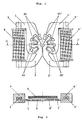
- FIG. 1 represents the top plan view of the magnetic circuit of a first embodiment of the motor.
- the motor has 7 pairs of blades and 2 phases.
- the magnetic circuit of each phase consists of an outer pole piece (1, 1 '), an inner pole piece (2, 2'); the 2 pole pieces are arranged in the same plane parallel to that of rotor 5 as illustrated in FIG. 2.
- the 2 pole pieces of each phase are each connected to one end of a coil core (3, 3 ') carrying a coil (4, 4 ').
- the inner pole piece (2, 2 ') has teeth with a tooth pitch equal to 2 ⁇ / 7.
- the outer pole piece (1, 1 ') has 2 separate toothed zones.
- the first toothed area (d1, d1 ') located inside has a dental pitch of 2 ⁇ / 7; the teeth of the first zone of the external stator are entangled with those of the internal stator.
- This structure creates, under the effect of the current in the phase windings, a stator induction distribution of the same period as that created by the rotor magnet and, therefore, an interaction torque with the magnet of the rotor.
- the second toothed zone of the external stator, located outside the first zone has a dental pitch of 2 ⁇ / 14. This second toothed zone creates, by interaction with the induction of the rotor and under the effect of the variation in permeance, a holding torque with a period 2 times smaller than that of the torque created by the current in the first zone. It is noted that the toothed structures of the two zones are offset relative to each other, this in order to obtain a favorable starting torque.
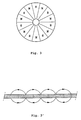
- Figure 3 shows the schematic plan view of the rotor magnet with 7 pairs of blades (N, S) distributed around a central axis perpendicular to the plane of the drawing.
- FIG. 4 represents the schematic plan view of the magnetic circuit of a second embodiment of the motor.
- the 2 inner pole pieces of the motor form a single assembly thus making it possible, on the one hand to mechanically reinforce these pieces and on the other hand to facilitate the mounting of these pieces.
- a toothed area d3 can be created which contributes to the total holding torque.
- FIG. 5 For the same purpose of facilitating the mounting of the motor, a third embodiment of the motor is shown in FIG. 5.
- the 2 outer pole pieces of the stator are connected together by fasteners (a) of reduced sections to mechanically form a single assembly.
- This assembly easily obtained by stamping, facilitates the mounting of the pole pieces.
- the fasteners (a) by their reduced section, have only a purely mechanical role and do not modify the operation of the engine.
- FIG. 6 represents an alternative embodiment of the motor in which the coil cores form a single assembly with the outer pole pieces.
- the latter is folded at levels p1 and p2.
- Figures 7 and 7 ' show an alternative embodiment of the engine with a reduced diameter rotor.
- the holding torque of the rotor is obtained by friction between the rotor and its seat under the effect of the magnetic attraction force between the rotor magnet and the stator magnetic circuit instead of the double toothing system.
- the external stator part of the previous embodiments.
Landscapes
- Engineering & Computer Science (AREA)
- Power Engineering (AREA)
- Iron Core Of Rotating Electric Machines (AREA)
- Connection Of Motors, Electrical Generators, Mechanical Devices, And The Like (AREA)
Priority Applications (3)
| Application Number | Priority Date | Filing Date | Title |
|---|---|---|---|
| DE1994601665 DE69401665T2 (de) | 1994-12-12 | 1994-12-12 | Mehrphasiger vielpoliger Schnittmotor |
| EP19940810717 EP0718960B1 (de) | 1994-12-12 | 1994-12-12 | Mehrphasiger vielpoliger Schnittmotor |
| CN 95121629 CN1131840A (zh) | 1994-12-12 | 1995-12-12 | 多相多极步进电动机 |
Applications Claiming Priority (1)
| Application Number | Priority Date | Filing Date | Title |
|---|---|---|---|
| EP19940810717 EP0718960B1 (de) | 1994-12-12 | 1994-12-12 | Mehrphasiger vielpoliger Schnittmotor |
Publications (2)
| Publication Number | Publication Date |
|---|---|
| EP0718960A1 true EP0718960A1 (de) | 1996-06-26 |
| EP0718960B1 EP0718960B1 (de) | 1997-01-29 |
Family
ID=8218352
Family Applications (1)
| Application Number | Title | Priority Date | Filing Date |
|---|---|---|---|
| EP19940810717 Expired - Lifetime EP0718960B1 (de) | 1994-12-12 | 1994-12-12 | Mehrphasiger vielpoliger Schnittmotor |
Country Status (3)
| Country | Link |
|---|---|
| EP (1) | EP0718960B1 (de) |
| CN (1) | CN1131840A (de) |
| DE (1) | DE69401665T2 (de) |
Citations (7)
| Publication number | Priority date | Publication date | Assignee | Title |
|---|---|---|---|---|
| FR2361014A1 (fr) * | 1976-05-06 | 1978-03-03 | Suisse Horlogerie | Moteur electromagnetique pas a pas |
| FR2406907A1 (fr) * | 1977-10-24 | 1979-05-18 | Quarz Zeit Ag | Moteur monophase pas a pas, en particulier pour horloges, et dont l'arbre du rotor est monte sur un coussinet fixe sur une surface polaire du stator |
| WO1982000929A1 (fr) * | 1980-08-29 | 1982-03-18 | Sa Elessach | Moteur pas a pas, notamment pour montre electronique |
| JPS5996862A (ja) * | 1982-11-22 | 1984-06-04 | Tokyo Electric Co Ltd | ステツピングモ−タ |
| WO1985000704A1 (fr) * | 1983-07-28 | 1985-02-14 | Michel Grosjean | Moteur polyphase a rotor aimante presentant n paires de poles a aimantation axiale |
| JPH03251071A (ja) * | 1990-02-23 | 1991-11-08 | Olympus Optical Co Ltd | 電子カメラ |
| WO1992011686A1 (fr) * | 1990-12-17 | 1992-07-09 | Moving Magnet Technologies S.A. | Actionneur electromagnetique monophase rotatif |
-
1994
- 1994-12-12 EP EP19940810717 patent/EP0718960B1/de not_active Expired - Lifetime
- 1994-12-12 DE DE1994601665 patent/DE69401665T2/de not_active Expired - Fee Related
-
1995
- 1995-12-12 CN CN 95121629 patent/CN1131840A/zh active Pending
Patent Citations (7)
| Publication number | Priority date | Publication date | Assignee | Title |
|---|---|---|---|---|
| FR2361014A1 (fr) * | 1976-05-06 | 1978-03-03 | Suisse Horlogerie | Moteur electromagnetique pas a pas |
| FR2406907A1 (fr) * | 1977-10-24 | 1979-05-18 | Quarz Zeit Ag | Moteur monophase pas a pas, en particulier pour horloges, et dont l'arbre du rotor est monte sur un coussinet fixe sur une surface polaire du stator |
| WO1982000929A1 (fr) * | 1980-08-29 | 1982-03-18 | Sa Elessach | Moteur pas a pas, notamment pour montre electronique |
| JPS5996862A (ja) * | 1982-11-22 | 1984-06-04 | Tokyo Electric Co Ltd | ステツピングモ−タ |
| WO1985000704A1 (fr) * | 1983-07-28 | 1985-02-14 | Michel Grosjean | Moteur polyphase a rotor aimante presentant n paires de poles a aimantation axiale |
| JPH03251071A (ja) * | 1990-02-23 | 1991-11-08 | Olympus Optical Co Ltd | 電子カメラ |
| WO1992011686A1 (fr) * | 1990-12-17 | 1992-07-09 | Moving Magnet Technologies S.A. | Actionneur electromagnetique monophase rotatif |
Non-Patent Citations (2)
| Title |
|---|
| PATENT ABSTRACTS OF JAPAN vol. 16, no. 48 (E - 1163) 6 February 1992 (1992-02-06) * |
| PATENT ABSTRACTS OF JAPAN vol. 8, no. 213 (E - 269)<1650> 28 September 1984 (1984-09-28) * |
Also Published As
| Publication number | Publication date |
|---|---|
| DE69401665D1 (de) | 1997-03-13 |
| CN1131840A (zh) | 1996-09-25 |
| DE69401665T2 (de) | 1997-07-31 |
| EP0718960B1 (de) | 1997-01-29 |
Similar Documents
| Publication | Publication Date | Title |
|---|---|---|
| EP0949747B1 (de) | Mehrphasenmotor, insbesondere zum antrieb eines zeigers einer anzeige | |
| EP0811269B1 (de) | Zweiphasenmotor,insbesondere für zeitmessgerät oder zum antrieb eines zeigers einer anzeige | |
| FR2823616A1 (fr) | Machine electrique comportant au moins un detecteur de champ magnetique | |
| EP0201022A2 (de) | Elektrischer Synchronmotor mit scheibenförmigem Läufer | |
| FR2762722A1 (fr) | Machine electrique a double excitation perfectionnee | |
| EP1082804B1 (de) | Rotierende maschine mit verbesserter erregung | |
| EP0866539A1 (de) | Elektrische Rotationsmaschine mit Wicklungserregung, Permanentmagneterregung oder überlagerter Erregung | |
| EP2201662A1 (de) | Elektromotor zum betreiben eines blendenelements oder eines sonnenschutzelements in einem gebäude | |
| CH665069A5 (fr) | Moteur electrique synchrone di- ou tetraphase a un etage. | |
| EP0945966B1 (de) | Elektromotor | |
| FR2920259A1 (fr) | Machine electrique tournante, en particulier pour un demarreur automobile | |
| WO2015193562A1 (fr) | Moteur synchrone électromagnétique à flux magnétiques combinés axial et radial | |
| EP3164929A2 (de) | Elektromagnetischer motor mit radialen luftspalten und einem von zwei statoren umgebenden rotor zur verringerung des rastmoments | |
| CH676647A5 (de) | ||
| FR2622066A1 (fr) | Machine electrique a entrefers radiaux | |
| EP1156578B1 (de) | Scheibenförmiger Schrittmotor | |
| EP0718960B1 (de) | Mehrphasiger vielpoliger Schnittmotor | |
| CH672566A5 (de) | ||
| FR2846483A1 (fr) | Rotor pour machine electrique tournante a double excitation equipe de dents radiales, et machine electrique tournante a double excitation equipee de ce rotor | |
| FR2945683A1 (fr) | Machine vernier a aimants insires. | |
| FR2922060A1 (fr) | Machine electrique tournante comportant deux stators | |
| CH363710A (fr) | Machine électrique tournante à éléments discoïdaux | |
| FR2910192A1 (fr) | Machine electrique tournante, en particulier pour un demarreur de vehicule automobile | |
| FR2769766A3 (fr) | Moteur sans collecteur a vibrations reduites | |
| FR2848739A1 (fr) | Dispositif d'entrainement en rotation |
Legal Events
| Date | Code | Title | Description |
|---|---|---|---|
| PUAI | Public reference made under article 153(3) epc to a published international application that has entered the european phase |
Free format text: ORIGINAL CODE: 0009012 |
|
| GRAG | Despatch of communication of intention to grant |
Free format text: ORIGINAL CODE: EPIDOS AGRA |
|
| GRAG | Despatch of communication of intention to grant |
Free format text: ORIGINAL CODE: EPIDOS AGRA |
|
| 17P | Request for examination filed |
Effective date: 19941216 |
|
| AK | Designated contracting states |
Kind code of ref document: A1 Designated state(s): CH DE FR GB IT LI |
|
| GRAH | Despatch of communication of intention to grant a patent |
Free format text: ORIGINAL CODE: EPIDOS IGRA |
|
| GRAH | Despatch of communication of intention to grant a patent |
Free format text: ORIGINAL CODE: EPIDOS IGRA |
|
| GRAA | (expected) grant |
Free format text: ORIGINAL CODE: 0009210 |
|
| AK | Designated contracting states |
Kind code of ref document: B1 Designated state(s): CH DE FR GB IT LI |
|
| PG25 | Lapsed in a contracting state [announced via postgrant information from national office to epo] |
Ref country code: IT Free format text: LAPSE BECAUSE OF FAILURE TO SUBMIT A TRANSLATION OF THE DESCRIPTION OR TO PAY THE FEE WITHIN THE PRE;WARNING: LAPSES OF ITALIAN PATENTS WITH EFFECTIVE DATE BEFORE 2007 MAY HAVE OCCURRED AT ANY TIME BEFORE 2007. THE CORRECT EFFECTIVE DATE MAY BE DIFFERENT FROM THE ONE RECORDED.SCRIBED TIME-LIMIT Effective date: 19970129 |
|
| REG | Reference to a national code |
Ref country code: CH Ref legal event code: EP |
|
| REG | Reference to a national code |
Ref country code: CH Ref legal event code: NV Representative=s name: BOVARD AG PATENTANWAELTE |
|
| REF | Corresponds to: |
Ref document number: 69401665 Country of ref document: DE Date of ref document: 19970313 |
|
| GBT | Gb: translation of ep patent filed (gb section 77(6)(a)/1977) |
Effective date: 19970409 |
|
| K2C3 | Correction of patent specification (complete document) published |
Effective date: 19970129 |
|
| PLBE | No opposition filed within time limit |
Free format text: ORIGINAL CODE: 0009261 |
|
| STAA | Information on the status of an ep patent application or granted ep patent |
Free format text: STATUS: NO OPPOSITION FILED WITHIN TIME LIMIT |
|
| 26N | No opposition filed | ||
| PGFP | Annual fee paid to national office [announced via postgrant information from national office to epo] |
Ref country code: FR Payment date: 19981110 Year of fee payment: 5 |
|
| PGFP | Annual fee paid to national office [announced via postgrant information from national office to epo] |
Ref country code: GB Payment date: 19981124 Year of fee payment: 5 |
|
| PGFP | Annual fee paid to national office [announced via postgrant information from national office to epo] |
Ref country code: DE Payment date: 19981125 Year of fee payment: 5 |
|
| PGFP | Annual fee paid to national office [announced via postgrant information from national office to epo] |
Ref country code: CH Payment date: 19981214 Year of fee payment: 5 |
|
| PG25 | Lapsed in a contracting state [announced via postgrant information from national office to epo] |
Ref country code: GB Free format text: LAPSE BECAUSE OF NON-PAYMENT OF DUE FEES Effective date: 19991212 |
|
| PG25 | Lapsed in a contracting state [announced via postgrant information from national office to epo] |
Ref country code: LI Free format text: LAPSE BECAUSE OF NON-PAYMENT OF DUE FEES Effective date: 19991231 Ref country code: CH Free format text: LAPSE BECAUSE OF NON-PAYMENT OF DUE FEES Effective date: 19991231 |
|
| GBPC | Gb: european patent ceased through non-payment of renewal fee |
Effective date: 19991212 |
|
| PG25 | Lapsed in a contracting state [announced via postgrant information from national office to epo] |
Ref country code: FR Free format text: LAPSE BECAUSE OF NON-PAYMENT OF DUE FEES Effective date: 20000831 |
|
| PG25 | Lapsed in a contracting state [announced via postgrant information from national office to epo] |
Ref country code: DE Free format text: LAPSE BECAUSE OF NON-PAYMENT OF DUE FEES Effective date: 20001003 |
|
| REG | Reference to a national code |
Ref country code: FR Ref legal event code: ST |