EP0722778B1 - Procédé et système pour récupérer l'agrégat des déchets de béton - Google Patents
Procédé et système pour récupérer l'agrégat des déchets de béton Download PDFInfo
- Publication number
- EP0722778B1 EP0722778B1 EP19960300192 EP96300192A EP0722778B1 EP 0722778 B1 EP0722778 B1 EP 0722778B1 EP 19960300192 EP19960300192 EP 19960300192 EP 96300192 A EP96300192 A EP 96300192A EP 0722778 B1 EP0722778 B1 EP 0722778B1
- Authority
- EP
- European Patent Office
- Prior art keywords
- mixture
- mortar
- gravel
- crushed
- sand
- Prior art date
- Legal status (The legal status is an assumption and is not a legal conclusion. Google has not performed a legal analysis and makes no representation as to the accuracy of the status listed.)
- Expired - Lifetime
Links
Images


Classifications
-
- B—PERFORMING OPERATIONS; TRANSPORTING
- B03—SEPARATION OF SOLID MATERIALS USING LIQUIDS OR USING PNEUMATIC TABLES OR JIGS; MAGNETIC OR ELECTROSTATIC SEPARATION OF SOLID MATERIALS FROM SOLID MATERIALS OR FLUIDS; SEPARATION BY HIGH-VOLTAGE ELECTRIC FIELDS
- B03B—SEPARATING SOLID MATERIALS USING LIQUIDS OR USING PNEUMATIC TABLES OR JIGS
- B03B9/00—General arrangement of separating plant, e.g. flow sheets
- B03B9/06—General arrangement of separating plant, e.g. flow sheets specially adapted for refuse
- B03B9/061—General arrangement of separating plant, e.g. flow sheets specially adapted for refuse the refuse being industrial
- B03B9/065—General arrangement of separating plant, e.g. flow sheets specially adapted for refuse the refuse being industrial the refuse being building rubble
-
- B—PERFORMING OPERATIONS; TRANSPORTING
- B03—SEPARATION OF SOLID MATERIALS USING LIQUIDS OR USING PNEUMATIC TABLES OR JIGS; MAGNETIC OR ELECTROSTATIC SEPARATION OF SOLID MATERIALS FROM SOLID MATERIALS OR FLUIDS; SEPARATION BY HIGH-VOLTAGE ELECTRIC FIELDS
- B03B—SEPARATING SOLID MATERIALS USING LIQUIDS OR USING PNEUMATIC TABLES OR JIGS
- B03B13/00—Control arrangements specially adapted for wet-separating apparatus or for dressing plant, using physical effects
-
- B—PERFORMING OPERATIONS; TRANSPORTING
- B03—SEPARATION OF SOLID MATERIALS USING LIQUIDS OR USING PNEUMATIC TABLES OR JIGS; MAGNETIC OR ELECTROSTATIC SEPARATION OF SOLID MATERIALS FROM SOLID MATERIALS OR FLUIDS; SEPARATION BY HIGH-VOLTAGE ELECTRIC FIELDS
- B03B—SEPARATING SOLID MATERIALS USING LIQUIDS OR USING PNEUMATIC TABLES OR JIGS
- B03B5/00—Washing granular, powdered or lumpy materials; Wet separating
- B03B5/02—Washing granular, powdered or lumpy materials; Wet separating using shaken, pulsated or stirred beds as the principal means of separation
-
- B—PERFORMING OPERATIONS; TRANSPORTING
- B03—SEPARATION OF SOLID MATERIALS USING LIQUIDS OR USING PNEUMATIC TABLES OR JIGS; MAGNETIC OR ELECTROSTATIC SEPARATION OF SOLID MATERIALS FROM SOLID MATERIALS OR FLUIDS; SEPARATION BY HIGH-VOLTAGE ELECTRIC FIELDS
- B03B—SEPARATING SOLID MATERIALS USING LIQUIDS OR USING PNEUMATIC TABLES OR JIGS
- B03B5/00—Washing granular, powdered or lumpy materials; Wet separating
- B03B5/28—Washing granular, powdered or lumpy materials; Wet separating by sink-float separation
-
- E—FIXED CONSTRUCTIONS
- E01—CONSTRUCTION OF ROADS, RAILWAYS, OR BRIDGES
- E01C—CONSTRUCTION OF, OR SURFACES FOR, ROADS, SPORTS GROUNDS, OR THE LIKE; MACHINES OR AUXILIARY TOOLS FOR CONSTRUCTION OR REPAIR
- E01C19/00—Machines, tools or auxiliary devices for preparing or distributing paving materials, for working the placed materials, or for forming, consolidating, or finishing the paving
- E01C19/02—Machines, tools or auxiliary devices for preparing or distributing paving materials, for working the placed materials, or for forming, consolidating, or finishing the paving for preparing the materials
- E01C19/05—Crushing, pulverising or disintegrating apparatus; Aggregate screening, cleaning, drying or heating apparatus; Dust-collecting arrangements specially adapted therefor
-
- Y—GENERAL TAGGING OF NEW TECHNOLOGICAL DEVELOPMENTS; GENERAL TAGGING OF CROSS-SECTIONAL TECHNOLOGIES SPANNING OVER SEVERAL SECTIONS OF THE IPC; TECHNICAL SUBJECTS COVERED BY FORMER USPC CROSS-REFERENCE ART COLLECTIONS [XRACs] AND DIGESTS
- Y02—TECHNOLOGIES OR APPLICATIONS FOR MITIGATION OR ADAPTATION AGAINST CLIMATE CHANGE
- Y02W—CLIMATE CHANGE MITIGATION TECHNOLOGIES RELATED TO WASTEWATER TREATMENT OR WASTE MANAGEMENT
- Y02W30/00—Technologies for solid waste management
- Y02W30/50—Reuse, recycling or recovery technologies
- Y02W30/52—Mechanical processing of waste for the recovery of materials, e.g. crushing, shredding, separation or disassembly
-
- Y—GENERAL TAGGING OF NEW TECHNOLOGICAL DEVELOPMENTS; GENERAL TAGGING OF CROSS-SECTIONAL TECHNOLOGIES SPANNING OVER SEVERAL SECTIONS OF THE IPC; TECHNICAL SUBJECTS COVERED BY FORMER USPC CROSS-REFERENCE ART COLLECTIONS [XRACs] AND DIGESTS
- Y02—TECHNOLOGIES OR APPLICATIONS FOR MITIGATION OR ADAPTATION AGAINST CLIMATE CHANGE
- Y02W—CLIMATE CHANGE MITIGATION TECHNOLOGIES RELATED TO WASTEWATER TREATMENT OR WASTE MANAGEMENT
- Y02W30/00—Technologies for solid waste management
- Y02W30/50—Reuse, recycling or recovery technologies
- Y02W30/58—Construction or demolition [C&D] waste
-
- Y—GENERAL TAGGING OF NEW TECHNOLOGICAL DEVELOPMENTS; GENERAL TAGGING OF CROSS-SECTIONAL TECHNOLOGIES SPANNING OVER SEVERAL SECTIONS OF THE IPC; TECHNICAL SUBJECTS COVERED BY FORMER USPC CROSS-REFERENCE ART COLLECTIONS [XRACs] AND DIGESTS
- Y10—TECHNICAL SUBJECTS COVERED BY FORMER USPC
- Y10S—TECHNICAL SUBJECTS COVERED BY FORMER USPC CROSS-REFERENCE ART COLLECTIONS [XRACs] AND DIGESTS
- Y10S241/00—Solid material comminution or disintegration
- Y10S241/38—Solid waste disposal
Definitions
- the present invention relates to a method for reclaiming aggregate from concrete waste material and a system therefor, which are capable of separating high quality aggregate such as gravel, crushed stones and sand from concrete waste material produced in construction sites to reclaim the same.
- the above concrete waste lumps include aggregate such as gravel, crushed stones and sand, unreacted cement or the like, which cause difficulty in recycling the concrete waste lumps. To overcome this difficulty, sufficient removal of mortar attached to aggregate is required. This requirement, however, has not been satisfied as yet so that effective recycle of the aggregate, unreacted cement, or the like has not been performed up to the present.
- the method in accordance with the present invention includes a crushing step of compression-crushing concrete waste lumps into a crushed mixture, and sorting the crushed mixture by size thereof, a grinding step of rotating the sorted crushed mixture to grind the sorted crushed mixture, thereby peeling mortar from aggregate included in the sorted crushed mixture to obtain a mixture of aggregate and mortar, and sorting the mixture of aggregate and mortar into a mixture of gravel, crushed stones and mortar and a mixture of sand, cement and mortar, and a product separating step of separating the mixture of gravel, crushed stones and mortar and the mixture of sand, cement and mortar into gravel, crushed stones, sand, cement and mortar.
- the crushed mixture is sorted into a mixture of gravel and crushed stones and a mixture of sand and cement
- the grinding step preferably includes a first grinding step of rotating the mixture of gravel and crushed stones crushed and sorted in the crushing step to grind the mixture, thereby peeling mortar from gravel and crushed stones, and a second grinding step of rotating the mixture of sand and cement crushed and sorted in the crushing step to grind the mixture, thereby peeling mortar from sand.
- the product separating step preferably includes a first separating step of separating the mixture of gravel, crushed stones and mortar into gravel, crushed stone and mortar, and a second separating step of separating the mixture of sand, cement and mortar into sand, cement and mortar.
- the mixture of gravel, crushed stones and mortar is separated by size thereof based on the difference in gravity therebetween.
- the mixture of gravel, crushed stones and mortar is separated by applying vibrations.
- the mixture of gravel, crushed stones and mortar is separated by applying pressures.
- the mixture of sand, cement and mortar is separated by rotating the mixture.
- the system in accordance with the present invention includes crushing means of compression-crushing concrete waste lumps into a crushed mixture and sorting the crushed mixture by size thereof, grinding means of rotating the sorted crushed mixture to grind the sorted crushed mixture, thereby peeling mortar from agregate included in the sorted crushed mixture to obtain a mixture of aggregate and mortar, and sorting the mixture of aggregate and mortar into a mixture of gravel, crushed stones and mortar and a mixture or sand, cement and mortar, and product separating means of separating the mixture of gravel, crushed stones and mortar and the mixture of sand, cement and mortar into gravel, crushed stones, sand, cement and mortar.
- the crushing means sorts the crushed mixture into a mixture of gravel and crushed stones and a mixture of sand and cement
- the grinding means includes first grinding means of rotating the mixture of gravel and crushed stones crushed and sorted by the crushing means to grind the mixture, thereby peeling mortar from gravel and crushed stones, and second grinding means of rotating the mixture of sand and cement crushed and sorted by the crushing means to grind the mixture, thereby peeling mortar from sand.
- the product separating means includes first separating means of separating the mixture of gravel, crushed stones and mortar into gravel, crushed stones and mortar, and second separating means of separating the mixture of sand, cement and mortar into sand, cement and mortar.
- the grinding means is composed of at least two grinding devices, each having a tubular rotary main body.
- the grinding device further has a grinding member such as rods and balls, which are movably provided within the tubular rotary main body.
- the grinding device further has a grinding member composed of a rotary body provided within the tubular rotary main body in eccentric relation therewith so as to rotate in a direction opposite to that of the tubular rotary main body.
- the rotary body has in an outside face thereof a plurality of longitudinal extending plate-shaped projections which respectively face a plurality of longitudinal extending plate-shaped projections formed in an inside face of the tubular rotary main body.
- the first product separating means is composed of at least one gravity sorting device which separates the mixture of gravel, crushed stones and mortar based on the difference in gravity therebetween by applying vibrations or pressures.
- the second product separating means is composed of a spiral classifier of separating sand, cement and mortar from each other by rotating spiral vanes of the spiral classifier.
- the tubular rotary main body has an inlet opening and an outlet opening at axially facing positions thereof, and a cylindrical side wall thereof is tapered to the outlet opening such that the diameter of the tubular rotary main body decreases towards the outlet opening.
- the tubular rotary main body has an inlet opening and an outlet opening at axially facing positions thereof, and an adjusting plate capable of varying the opening area of the outlet opening is provided along the outlet opening.
- a plurality of grinding devices can be used in accordance with the sizes of the aggregate to peel mortar therefrom with certainty, and in the product separating step and means, a plurality of sorting devices can be used in series to sort mortar and aggregate with certainty.
- mortar can be sufficiently peeled from aggregate such as sand, gravel and crushed stones, whereby high quality aggregate free from a large amount of mortar attachment, which conforms to the legal standard, can be reclaimed.
- the crushed mixture is ground between the tubular rotary main body of the grinding device and the grinding member so that mortar can be peeled from the aggregate such as sand, gravel and crushed stones with certainty.
- the crushed mixture is ground between the rotating main body and the rotary body which is rotated in eccentric relation with the rotating main body so that mortar can be peeled from aggregate with more certainty.
- vibrations are applied to the mixture of gravel, crushed stones and mortar, they can be separated from each other based on the difference in gravity therebetween.
- pressures are applied to the mixture of gravel, crushed stones and mortar, they can be separated from each other based on the difference in gravity therebetween.
- FIGS. 1 to 3 illustrate a first embodiment of the present invention.
- FIG. 1 is a flow diagram including a crushing step, grinding step and product separating step.
- concrete waste lumps B produced in a construction site are carried by a truck k, and thrown into a concrete hopper 10 by a shavel S or the like. Then, the concrete waste lumps B are conveyed by a recipro-feeder 12 and thrown into a jaw crusher 14.
- the jaw crusher 14 has a fixed plate 16 and a movable plate 18 which is reciprocated by a rotating body 20 towards the fixed plate 16.
- the concrete waste lumps B thrown are crushed between the fixed plate 16 and the movable plate 18 and sorted by a vibrating screen 22 into a mixture of sand and cement having diameters of less than 5 mm and a mixture of gravel and crushed stones having diameters of greater than 5 mm.
- the mixture of gravel and crushed stones is fed to a grinding device 24 and the mixture of sand and cement is fed to a grinding device 26.
- the mixture of gravel and crushed stones can be further sorted by nets or the like into several kinds of mixtures by diameter thereof, for example, one being greater than 30 mm and less than 60 mm, another being greater than 60 mm and less than 100 mm and still another being greater than 100 mm, and fed to a plurality of grinding devices, respectively. Gravel and crushed stones of diameters which are unnecessarily great are removed.
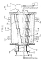
- the grinding device 24 includes a tubular rotary main body 28 having an inlet opening 30 and an outlet opening 32 which are respectively formed in axially end faces of the main body 28 in facing relationship, and a plurality of rods 34 movably disposed within the main body 28.
- the preferred total volume of the rods 34 ranges from 10 to 20 % of the volume of the inside of the main body 28.
- the cylindrical side wall of the main body 28 is tapered towards the outlet opening 32 such that the diameter of the main body 28 decreases towards the outlet opening 32.
- the grinding device 24 further includes an adjusting plate 36 which is movably attached along the outlet opening 32 to vary the opening area thereof.
- a pair of ring-like members 38 are integrally formed. These ring-like members 38 are driven by drive wheels 40 having a cushion property at a predetermined speed. Furthermore, wheels (not shown) composed of tires are provided in abutment with the side parts of the ring-like members 38 to axially and rotatably support the main body 28.
- the gravel and crushed stones sorted in the crushing step are thrown with water into the grinding device 24 from the inlet opening 30.
- the main body 28 is rotated by the drive wheels 40 through the ring-like members 38 at the predetermined speed. Due to the rotation of the main body 28, gravel and crushed stones rotate along an inner face of the main body 28, and the plurality of rods 34 repeatedly move upwardly along the inner face of the main body 28 and drop, whereby gravel and crushed stones are ground between the inner face of the rotating main body 28 and the plurality of rods 34 to peel mortar from the gravel and crushed stones.
- the grinding step is carried out under such conditions that gravel and crushed stones do not collide violently with each other but merely abut each other so that the crush thereof can be restrained to a minimum.
- the ground gravel and crushed stones are fed from the outlet opening 32 of the grinding device 24 together with mortar.
- the opening area of the outlet opening 32 is adjusted to set the grinding time enough to peel mortar from the gravel and crushed stones completely.
- a trommel revolving screen 42 having a wire net-like sieve 44 is provided outside the outlet opening 32 of the grinding device 24 .
- the sieve 44 sorts a mixture of sand and cement from the mixture of ground gravel, crushed stones and mortar.
- the gravel and crushed stones thrown into the main body 28 can readily move towards the outlet opening 32, and can properly stay near the outlet opening 32 to enable the uniform grinding of the gravel and crushed stones.
- the grinding device 26 (FIG. 1) has a construction substantially identical to that of the grinding device 24.
- the mixture of sand and cement sorted by the wire net-like sieve 44 is thrown with the mixture of sand and cement passing the vibrating screen 22 into the grinding device 26, and ground together similarly to the grinding device 24 to peel mortar from sand.
- rods 34 are used. Alternatively, balls made of iron or other metal will do. Furthermore, these rods or balls are not always needed within the main body 28. In this case, gravel and crushed stones are rotated under such conditions as not to crush them with each other.
- the gravity sorting device 46 In the product separating step, the mixture of gravel, crushed stones and mortar fed from the grinding device 24 is thrown into a gravity sorting device 46 (FIG. 1).
- the gravity sorting device 46 has a fixed water tank 48 which are partitioned with a punching plate 50 into an upper part and a lower part, and a movable water tank 52 which is separated from the fixed water tank 48 with a rubber diaphragm 54.
- the punching plate 50 slightly inclines downwards from an inlet position 56 towards an outlet opening 58.
- a driving member 60 Under the movable water tank 48, a driving member 60 which is driven by a high speed main motor 62 and a low speed sub motor 64 is provided.
- the mixture of gravel, crushed stones and mortar is thrown into the fixed water tank 48 from the inlet position 56.
- the driving member 60 driven by the high speed main motor 62 and the low speed sub motor 64 vibrates the water within the movable water tank 52.
- the vibrations of the water within the movable water tank 52 is transmitted to the water within the fixed water tank 48 through the rubber diaphragm 54. Due to the vibrations of the water within the fixed water tank 48, the mixture of gravel, crushed stones and mortar thrown into the fixed water tank 48 is moved towards the outlet side 58 while being separated with the punching plate 50 into high gravity gravel and crushed stones below the punching plate 50 and low gravity mortar thereabove.
- gravel and crushed stone J, mortar M and water W are separated from each other and discharged from the outlet opening 58 and a lower outlet opening (not shown).
- the mixture of sand, cement and mortar, which is fed from the grinding device 26 is thrown into a spiral classifier 66, and separated with the rotation of spiral vanes into sand N and powdery cement.
- the powdery cement is thickened with water fed from the gravity sorting device 46 by a thickner 68.
- extra water W is separated from water-including cement T and fed again to the gravity sorting device 46.
- the grinding step mortar can be removed from sand, gravel and crushed stones by the grinding devices 24 and 26 with certainty, which enables the reclaim of high quality sand, gravel and crushed stones.
- the product separating step can be carried out with certainty by means of the gravity sorting device and spiral classifier.
- FIGS. 4 to 7 illustrate a second embodiment of the present invention.
- FIG. 4 is a flow diagram including a crushing step, grinding step and product separating step.
- the crushing step is substantially idential to that of the first embodiment.
- Concrete waste lumps B produced in a construction site are carried by a truck k, and thrown into a concrete hopper 70 by a shavel S or the like. Then, the concrete waste lumps B are conveyed by a recipro-feeder 72 and thrown into a jaw crusher 74.
- the jaw crusher 74 has a fixed plate 76 and a movable plate 78 which is reciprocated by a rotating body 80 towards the fixed plate 76.
- the concrete waste lumps B thrown are crushed between the fixed plate 76 and the movable plate 78 and sorted by a vibrating screen 82 into a mixture of sand and cement having diameters of less than 5 mm and a mixture of gravel and crushed stones having diameters of greater than 5 mm.
- the mixture of gravel and crushed stones is fed to a grinding device 84 and the mixture of sand and cement is fed to a grinding device 86.
- the mixture of gravel and crushed stones can be further sorted by nets or the like into several kinds of mixtures by diameter thereof, for example, one being greater than 30 mm and less than 60 mm, another being greater than 60 mm and less than 100 mm, still another being greater than 100 mm, and fed to a plurality of grinding devices, respectively. Gravel and crushed stones of diameters which are unnecessarily great are removed.
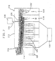
- the grinding device 84 includes a tubular rotary main body 88 having an inlet opening 90 and an outlet opening 92 which are respectively formed in axially end faces of the main body 88 in facing relationship, and a rotary body 94 which is disposed within the main body 88 in eccentric relation therewith so as to rotate in a direction opposite to that of the main body 88 at a predetermined speed.
- the main body 88 has along its inside face a large number of longitudinally extending plate-shaped projections 96, and the rotary body 94 has along its outside face a large number of longitudianlly extending plate-shaped projections 98 so as to face the projections 96 of the main body 88.
- the cylindrical side wall of the main body 88 is tapered towards the outlet opening 92 such that the diameter of the main body 88 decreases towards the outlet opening 92.
- the grinding device 84 further includes an adjusting plate 100 which is movably attached along the outlet opening 92 to vary the opening area thereof.
- a pair of ring-like members 102 are integrally formed. These ring-like members 102 are driven by drive wheels 104 having a cushion property at a predetermined speed. Furthermore, wheels (not shown) composed of tires are provided in abutment with the side parts of the ring-like members 102 to axially and rotatably support the main body 88.
- the gravel and crushed stones crushed in the crushing step is thrown with water into the grinding device 84 from the inlet opening 90.
- the mixture of gravel and crushed stones thrown are rotated along the inner face of the main body 88 and ground between the projections 96 and 98 while moving towards the outlet opening 92. Since the rotary body 94 is in eccentric relation with the main body 88, the grinding space between the rotary body 94 and the main body 88 varies to vary the compression forces of the projections 96 and 98 against gravel and crushed stones. The compression forces thereof become the maximum in the narrowest grinding space therebetween.
- the projections 96 and 98 respectively extend longitudinally into differently incluinded configurations. With this arrangement, gravel and crushed stones can be readily moved to the outlet opening 92. Alternatively, one or both of the projections 96 and 98 may be extend longitudinally along an axis of the main body 88 and the rotary body 94, respectively. With this arrangement, the staying time of gravel and crushed stones within the main body 88 can be prolonged to provide a compact main body having a shorter axial length.
- the ground gravel and crushed stones are fed from the outlet opening 92 of the grinding device 84 together with mortar.
- the opening area of the outlet opening 92 is adjusted to set the grinding time enough to peel mortar from the gravel and crushed stones completely.
- a trommel revolving screen 106 having a wire net-like sieve 108 is provided outside the outlet opening 92 of the grinding device 84.
- the sieve 108 sorts a mixture of sand and cement from the mixture of ground gravel, crushed stones and mortar.
- the side wall of the main body 88 is tapered to the outlet opening 92, the gravel and crushed stones thrown into the main body 88 can readily move towards the outlet opening 92, and can properly stay near the outlet opening 92 to enable the uniform grinding of the gravel and crushed stones.
- the grinding device 86 (FIG. 4) has a construction substantially identical to that of the grinding device 84.
- the mixture of sand and cement sorted by the wire net-like screen 108 is thrown with the mixture of sand and cement passing the vibrating screen 82 into the grinding device 86, and ground together similarly to the grinding device 84 to peel mortar from sand. Then, a mixture of sand, cement and mortar is fed from the grinding device 86.
- the pressure sorting device 110 has a main body 112 where a conveyor plate 114 having a lattice-like configuration is provided so as to incline slightly downwards from an inlet position 116 to outlet openings 118 and 120. Under the conveyor plate 114, a water pipe 122 and air pipes 124 interconnected with ends of the water pipe 122 are provided to inject compressed air with water towards the conveyor plate 114.
- a parting device 124 composed of a float section 126 adapted to make the upper level of the mixture of gravel, crushed stones and mortar uniform and part the mixture into gravel and crushed stones J and mortar M, and a control section 128 adapted to control the height of the float section 126 in accordance with the condition of the above mixture.
- Reference numeral 130 denotes a drain pan adapted to receive water and sand from the conveyor plate 114.
- the mixture of gravel, crushed stones and mortar from the grinding device 84 is thrown into the pressure sorting device 110 from the inlet position 116 and conveyed by the convey plate 114 within the main body 112.
- pressure is applied to the above mixture by the air with water injected from the air pipe 124 to sort the above mixture by density and gravity thereof into an upper layer of gravel and crushed stones and a lower layer of mortar.
- these upper and lower layers are parted by the parting device 124 on the conveyor plate 114.
- the gravel and crushed stones J move along a guide plate 132 and drop down from the outlet opening 120, and mortar M drops down from the outlet opening 118, thus separating gravel and crushed stones, mortar and water from each other.
- the mixture of sand, cement and mortar fed from the grinding device 86 is thrown into a spiral classifier 138, and sorted with the rotation of spiral vanes into sand N and a mixture of mortar and powdery cement.
- the powdery cement is thickened by a thickner 140 with water fed from the pressure sorting device 110 and bucket conveyors 134 and 136, and extra water is separated from water-including cement T and is again fed to the pressure sorting device 110.
- mortar in the grinding step, mortar can be removed from the aggregate by the grinding devices 84 and 86 with certainty while restraining the crush of the gravel and crushed stones to a minimum. This enables reclamation of high quality sand, gravel and crushed stone.
- the product separating step can be carried out with certainty by means of the pressure sorting device 110 and the spiral classifier 138.
- the experimental result of the reclaimed aggregate in accordance with the second embodiment is substantially identical to that of the first embodiment shown in the above tables. This result shows that the qualities of the reclaimed aggregate from concrete waste material are considerably superior to those of both the above described Standard and JIS.
- the grinding step and means of grinding crushed and sorted mixture to peel mortar from gravel, crushed stones sand, and the product separating step and means of separating gravel and crushed stone, sand, mortar or the like, high quality aggregate free from a large amount of mortar attachment, which conforms to the legal standard, can be reclaimed.
- aggregate such as sand, gravel and crushed stones abut each other and the grinding member while being rotated along the inner face of the main body. Therefore, as compared to the conventional dry-crumbling techniquue, the grinding of aggregate can be carried out over a wide outer face thereof, which enables the effective peeling or mortar therefrom.
- the grinding step and means of the present invention is carried out in a wet state and under such conditions that aggregate do not collide violently with each other and the grinding member, the crush of aggregate can be restrained to a minimum, and the grinding performance is improved, which enables the substantially complete peel of mortar from aggregate and the reclamation of high quality aggregate.
- a plurality of griding devices can he used according to the sizes of aggregate.
- the gravity sorting device, pressure sorting device and spiral classifier effect the substantially complete separation of sand, gravel and crushed stones, and mortar from each other enough to reclaim high quality aggregate.
- the first separating step is carried out based on the difference in gravity, the certain product separation can be effected as compared to the conventional methods using screens. With the arrangement that a plurality of gravity sorting devices and/or pressure sorting devices are used in series, the sorting effect is further improved.
- the side walls of the main bodies 28 and 88 of the grinding devices 24, 26, 84 and 86 are tapered.
- the side walls of the main bodies 28 and 88 need not necessarily be tapered.
Landscapes
- Engineering & Computer Science (AREA)
- Architecture (AREA)
- Civil Engineering (AREA)
- Structural Engineering (AREA)
- Processing Of Solid Wastes (AREA)
- Disintegrating Or Milling (AREA)
Claims (19)
- Procédé de récupération de l'agrégat de déchets de béton (B), comprenant :une étape de concassage consistant à concasser par compression des morceaux desdits déchets de béton (B) pour donner un mélange concassé et à trier ledit mélange concassé en fonction de la taille ;une étape de broyage consistant à entraíner en rotation ledit mélange concassé et trié afin de broyer ledit mélange concassé et trié, détachant ainsi le mortier de l'agrégat compris dans ledit mélange concassé et trié afin d'obtenir un mélange d'agrégat et de mortier (M) et à trier ledit mélange d'agrégat et de mortier (M) pour obtenir un mélange de gravier et pierres concassées (J) et de mortier (M) et un mélange de sable (N), de ciment (T) et de mortier (M) ; etune étape de séparation des produits consistant à séparer ledit mélange de gravier et pierres concassées (J) et mortier (M) et ledit mélange de sable (N), ciment (T) et mortier (M) en gravier et pierres concassées (J), sable (N), ciment (T), mortier (M) ou similaire.
- Procédé selon la revendication 1, dans lequel, lors de ladite étape de concassage, ledit mélange concassé est trié pour obtenir un mélange de gravier et de pierres concassées (J) et un mélange de sable (N) et de ciment (T), ladite étape de broyage comprend une première étape de broyage consistant à entraíner en rotation ledit mélange de gravier et de pierres concassées (J) concassé et trié à ladite étape de concassage afin de broyer ledit mélange, détachant ainsi le mortier (M) du gravier et des pierres concassées (J), et une deuxième étape de broyage consistant à entraíner en rotation ledit mélange de sable (N) et de ciment (T) concassé et trié à ladite étape de concassage afin de broyer ledit mélange, détachant ainsi le mortier (M) du sable (N).
- Procédé selon la revendication 1, dans lequel ladite étape de séparation des produits comprend une première étape de séparation consistant à séparer ledit mélange de gravier et pierres concassées (J) et de mortier (M) en gravier et pierres concassées (J) et mortier (M), et une deuxième étape de séparation consistant à séparer ledit mélange de sable (N), de ciment (T) et de mortier (M) en sable (N), ciment (T) et mortier (M).
- Procédé selon la revendication 3, dans lequel ladite première étape de séparation consiste à séparer ledit mélange de gravier et pierres concassées (J) et de mortier (M) en fonction de la taille et en se basant sur la différence de gravité existant entre les produits.
- Procédé selon la revendication 4, dans lequel ladite première étape de séparation consiste à séparer ledit mélange de gravier et pierres concassées (J) et mortier (M) en y appliquant des vibrations.
- Procédé selon la revendication 4, dans lequel ladite première étape de séparation consiste à séparer ledit mélange de gravier et pierres concassées (J) et mortier (M) en y appliquant des pressions.
- Procédé selon la revendication 3, dans lequel ladite deuxième étape de séparation consiste à séparer ledit mélange de sable (N), ciment (T) et mortier (M) en entraínant ledit mélange en rotation.
- Système pour récupérer l'agrégat de déchets de béton (B) comprenant :des moyens de concassage (14, 22 ou 74, 82) destinés à concasser par compression des morceaux desdits déchets de béton (B) pour donner un mélange concassé et à trier ledit mélange concassé en fonction de la taille ;des moyens de broyage (24, 26 ou 84, 86) destinés à entraíner en rotation ledit mélange concassé et trié afin de broyer ledit mélange concassé et trié, détachant ainsi le mortier de l'agrégat compris dans ledit mélange concassé et trié afin d'obtenir un mélange d'agrégat et de mortier et à trier ledit mélange d'agrégat et de mortier pour obtenir un mélange de gravier, de pierres concassées et de mortier et un mélange de sable, de ciment et de mortier, etdes moyens de séparation des produits (46, 66 ou 110, 138) destinés à séparer ledit mélange de gravier, pierres concassées et mortier et ledit mélange de sable, ciment et mortier en gravier et pierres concassées (J), sable (N), ciment (T) et mortier (M) ou similaires.
- Système selon la revendication 8, dans lequel lesdits moyens de concassage (14, 22 ou 74, 82) trient ledit mélange concassé pour donner un mélange de gravier et de pierres concassées et un mélange de sable et de ciment, lesdits moyens de broyage (24, 26 ou 84, 86) comprennent des premiers moyens de broyage (24 ou 84) destinés à entraíner en rotation ledit mélange de gravier et de pierres concassées concassé et trié par lesdits moyens de concassage (14, 22 ou 74, 82) afin de broyer ledit mélange, détachant ainsi le mortier du gravier et des pierres concassées, et des deuxièmes moyens de broyage (26 ou 86) destinés à entraíner en rotation ledit mélange de sable et de ciment concassé et trié par lesdits moyens de concassage (14, 22 ou 74, 82) afin de broyer ledit mélange, détachant ainsi le mortier du sable.
- Système selon la revendication 8, dans lequel lesdits moyens de séparation des produits comprennent des premiers moyens de séparation (46 ou 110) destinés à séparer ledit mélange de gravier, pierres concassées et mortier en gravier et pierres concassées (J) et mortier (M), et des deuxièmes moyens de séparation (66 ou 138) destinés à séparer ledit mélange de sable, ciment et mortier en sable (N), ciment (T) et mortier (M).
- Système selon la revendication 8, dans lequel lesdits moyens de broyage (24, 26 ou 84, 86) sont composés d'au moins deux dispositifs de broyage (24, 26 ou 84, 86) ayant chacun un corps principal rotatif tubulaire (28 ou 88).
- Système selon la revendication 11, dans lequel chacun desdits au moins deux dispositifs de broyage (24, 26 ou 84, 86) possède en outre un organe de broyage (34 ou 94) prévu de manière mobile à l'intérieur dudit corps principal rotatif tubulaire (28 ou 88).
- Système selon la revendication 12, dans lequel ledit organe de broyage (34 ou 94) est un élément parmi des barres (34) ou des billes.
- Système selon la revendication 12, dans lequel ledit organe de broyage est un corps rotatif (94) disposé à l'intérieur dudit corps principal rotatif tubulaire (88) en relation excentrique avec celui-ci afin de tourner dans une direction opposée à celle dudit corps principal rotatif tubulaire (88), ledit corps rotatif (94) présente le long d'une face extérieure de celui-ci une pluralité de saillies plates s'étendant longitudinalement (98) qui sont respectivement tournées vers une pluralité de saillies plates s'étendant longitudinalement (96) formées le long d'une face intérieure dudit corps principal rotatif tubulaire (88).
- Système selon la revendication 10, dans lequel lesdits premiers moyens de séparation des produits (46 ou 110) sont composés d'au moins un dispositif de triage en fonction de la gravité (46) qui sépare ledit mélange de gravier et pierres concassées (J) et de mortier (M) en fonction de la différence de gravité entre eux en appliquant des vibrations.
- Système selon la revendication 10, dans lequel lesdits premiers moyens de séparation des produits (46 ou 110) sont composés d'au moins un dispositif de triage en fonction de la pression (110) qui sépare ledit mélange de gravier et pierres concassées (J) et de mortier (M) en fonction de la différence de gravité entre eux en appliquant des pressions.
- Système selon la revendication 8, dans lequel lesdits deuxièmes moyens de séparation des produits sont composés d'un classificateur à vis hélicoïdale (66) destiné à séparer le sable (N), le ciment (T) et le mortier (M) les uns des autres en entraínant en rotation les ailettes hélicoïdales dudit classificateur à vis hélicoïdale (66).
- Système selon la revendication 11, dans lequel ledit corps principal rotatif tubulaire (28 ou 88) possède une ouverture d'admission (30 ou 90) et une ouverture de décharge (32 ou 92) dans des positions axialement face à face de celles-ci, et une paroi latérale cylindrique de celui-ci est effilée vers ladite ouverture de décharge (32 ou 92) de telle sorte que le diamètre dudit corps principal rotatif tubulaire (28 ou 88) diminue vers ladite ouverture de décharge.
- Système selon la revendication 11, dans lequel ledit corps principal rotatif tubulaire (28 ou 88) possède une ouverture d'admission (30 ou 90) et une ouverture de décharge (32 ou 92) dans des positions axialement face à face de celles-ci, et une plaque de réglage (36 ou 100) capable de modifier la surface d'ouverture de ladite ouverture de décharge (32 ou 92) est prévue le long de ladite ouverture de décharge (32 ou 92).
Applications Claiming Priority (6)
| Application Number | Priority Date | Filing Date | Title |
|---|---|---|---|
| JP1861595 | 1995-01-10 | ||
| JP1861595 | 1995-01-10 | ||
| JP18615/95 | 1995-01-10 | ||
| JP35283395 | 1995-12-28 | ||
| JP352833/95 | 1995-12-28 | ||
| JP35283395A JP3199622B2 (ja) | 1995-01-10 | 1995-12-28 | コンクリート廃材から骨材を再生する方法、再生骨材 |
Publications (2)
| Publication Number | Publication Date |
|---|---|
| EP0722778A1 EP0722778A1 (fr) | 1996-07-24 |
| EP0722778B1 true EP0722778B1 (fr) | 2000-05-03 |
Family
ID=26355318
Family Applications (1)
| Application Number | Title | Priority Date | Filing Date |
|---|---|---|---|
| EP19960300192 Expired - Lifetime EP0722778B1 (fr) | 1995-01-10 | 1996-01-10 | Procédé et système pour récupérer l'agrégat des déchets de béton |
Country Status (4)
| Country | Link |
|---|---|
| US (2) | US5699969A (fr) |
| EP (1) | EP0722778B1 (fr) |
| JP (1) | JP3199622B2 (fr) |
| DE (1) | DE69607992T2 (fr) |
Families Citing this family (62)
| Publication number | Priority date | Publication date | Assignee | Title |
|---|---|---|---|---|
| RU2081259C1 (ru) * | 1995-02-22 | 1997-06-10 | Научно-исследовательский институт высоких напряжений при Томском политехническом университете | Способ изготовления изделий из некондиционного железобетона |
| US5833863A (en) * | 1997-04-21 | 1998-11-10 | Tuboscope Vetco Int'l Inc. | Concrete reclamation system |
| KR100358899B1 (ko) * | 2000-11-06 | 2002-10-31 | 주식회사 협진산업 | 폐콘크리트 골재화장치 |
| KR100413325B1 (ko) * | 2001-01-11 | 2003-12-31 | 주식회사 천보환경 | 폐콘크리트 재생골재의 입형 및 품질개선장치 |
| SG93923A1 (en) * | 2001-06-14 | 2003-01-21 | Hock Chuan Hong Waste Man Pte | Method for recycling construction wastes |
| US6582610B2 (en) | 2001-06-27 | 2003-06-24 | Varco I/P, Inc. | Concrete grindings reclamation system |
| JP4676107B2 (ja) * | 2001-09-03 | 2011-04-27 | 西松建設株式会社 | 再生骨材製造装置および再生骨材の製造方法 |
| KR100467419B1 (ko) * | 2001-10-19 | 2005-01-24 | 주식회사 신텍 | 폐기물의 고도 처리방법 |
| KR20030064185A (ko) * | 2002-01-26 | 2003-07-31 | (주)대명크라샤 | 건설폐기물 골재화 장치 및 재생모래 생산장치 |
| KR20030067411A (ko) * | 2002-02-08 | 2003-08-14 | 인선이엔티 주식회사 | 건설폐기물 처리와 추출 및 투입골재를 위한 가공장치 |
| KR20020042569A (ko) * | 2002-04-27 | 2002-06-05 | 기준호 | 폐 콘크리트를 이용한 재생 골재 제조방법 및 장치 |
| US20040040916A1 (en) * | 2002-09-04 | 2004-03-04 | Ruppert Donald J. | Concrete component reclamation process and system |
| KR100497318B1 (ko) * | 2002-11-07 | 2005-06-28 | 삼영플랜트주식회사 | 건설 폐기물을 이용한 재생 세 골재 제조방법 및 장치 |
| KR100487089B1 (ko) * | 2003-05-07 | 2005-05-03 | 박훈일 | 건설폐기물 선별시스템 및 그 방법 |
| DE10331175B4 (de) * | 2003-07-10 | 2006-06-08 | Bauhaus Universität Weimar | Verfahren zur Verwertung von Abbruchmaterial von Bauwerken |
| EP1526219A3 (fr) * | 2003-10-24 | 2005-11-30 | Robert Taylor | Procédé et dispositif de classification et de nettoyage d'aggregats |
| JP4587023B2 (ja) * | 2004-05-11 | 2010-11-24 | 清水建設株式会社 | 骨材再生装置 |
| US20060113229A1 (en) * | 2004-12-01 | 2006-06-01 | Intray Consolidated Pty Ltd | Water management system |
| JP4676245B2 (ja) * | 2005-05-18 | 2011-04-27 | Eacle有限会社 | 再生細骨材の製造方法、並びに、再生細骨材 |
| KR100544233B1 (ko) * | 2005-05-30 | 2006-01-23 | 주식회사 신텍 | 공기순환형 이물질, 미분 제거수단을 포함한 양질의순환골재 생산 방법 및 그 장치 |
| AU2008264164B9 (en) * | 2008-07-11 | 2009-10-29 | Boral Resources (Vic.) Pty Limited | Method of producing recycled aggregate from concrete |
| ITMI20081958A1 (it) * | 2008-11-06 | 2010-05-07 | Massimo Cottafava | Procedimento per riciclare scarti ceramici e relativa apparecchiatura |
| ES2316327B1 (es) * | 2008-11-20 | 2010-02-08 | Pastor, S.A. | Prefabricado de hormigon y su procedimiento de obtencion. |
| JP5464887B2 (ja) * | 2009-04-01 | 2014-04-09 | 株式会社トクヤマ | 再生細骨材の製造方法 |
| JP2011111342A (ja) * | 2009-11-25 | 2011-06-09 | Kotobuki Giken Kogyo Kk | 磨鉱装置及び再生骨材の生産方法 |
| JP4685195B2 (ja) * | 2010-06-08 | 2011-05-18 | 株式会社宮本建材 | コンクリート廃材の再生利用装置 |
| WO2012125834A2 (fr) * | 2011-03-15 | 2012-09-20 | Nordell Lawrence K | Broyeur à marteaux et enclumes conjugués |
| CN102228866B (zh) * | 2011-04-18 | 2013-11-27 | 昆明理工大学 | 一种磨矿产品的复合分级方法及设备 |
| RU2503730C1 (ru) * | 2012-05-25 | 2014-01-10 | Олег Савельевич Кочетов | Установка утилизации бетона |
| CN103586257A (zh) * | 2013-11-05 | 2014-02-19 | 中联重科物料输送设备有限公司 | 建筑垃圾处理系统 |
| CN103611717A (zh) * | 2013-11-14 | 2014-03-05 | 中国科学院广州能源研究所 | 一种城市生活垃圾干湿联合分选系统 |
| US9481105B2 (en) | 2013-12-12 | 2016-11-01 | Watershed Materials, Llc | System, method and apparatus for fabricating environmental masonry units |
| CN103949321B (zh) * | 2014-05-09 | 2016-06-29 | 成都宏源铸造材料有限公司 | 孕育剂制粒生产线及其生产工艺和粉尘回收方法 |
| KR101489713B1 (ko) * | 2014-05-22 | 2015-02-04 | 주식회사 일진도시환경 | 폐 건축 골재 재생 시스템용 토분 혼합 세척수의 탈수장치 |
| JP6161586B2 (ja) * | 2014-10-02 | 2017-07-12 | コトブキ技研工業株式会社 | 粒状物質の磨砕装置 |
| CN104525360B (zh) * | 2014-12-24 | 2017-04-05 | 中冶长天国际工程有限责任公司 | 一种磨矿分级过程中矿浆浓度控制的方法和装置 |
| FR3032133A1 (fr) * | 2015-01-30 | 2016-08-05 | Soc De Transp Et De Location Pluvinage | Machine et installation de purification des granulats issus du beton |
| US10569238B2 (en) * | 2015-02-27 | 2020-02-25 | Watershed Materials, Llc | Vertical shaft high-shear mixer for de-agglomeration, and associated methods and systems |
| US10486345B2 (en) | 2015-02-27 | 2019-11-26 | Watershed Materials, Llc | Dynamic block press, and associated methods and systems |
| CN104741366B (zh) * | 2015-04-01 | 2016-11-09 | 山东连银山环保建材有限公司 | 一套生活垃圾焚烧处理设备及生活垃圾焚烧处理工艺 |
| US10138137B1 (en) * | 2016-03-15 | 2018-11-27 | Duane Perrin | Washout pan for thixotropic materials |
| CN105921245B (zh) * | 2016-06-14 | 2018-04-17 | 中交第二航务工程局有限公司 | 一种砼骨料加工方法及加工系统 |
| CN105921246B (zh) * | 2016-06-15 | 2018-08-03 | 江苏金雷建材有限公司 | 一种机制砂生产系统及其生产方法 |
| US10695696B2 (en) | 2016-12-28 | 2020-06-30 | Clean Slurry Technology Inc. | System for processing solid and liquid construction waste |
| US10421079B2 (en) * | 2017-02-22 | 2019-09-24 | Victor Zaguliaev | Method and apparatus for rock disintegration |
| CN106824357A (zh) * | 2017-03-01 | 2017-06-13 | 深圳市玖创科技有限公司 | 一种往复运动的多级石墨粉碎箱 |
| CN107803932B (zh) * | 2017-10-24 | 2024-03-22 | 重庆建工住宅建设有限公司 | 一种快硬无收缩混凝土生产设备 |
| KR101976741B1 (ko) * | 2018-07-19 | 2019-05-09 | (주)신영이앤피 | 펠릿 제조용 선별장치 |
| PE20211616A1 (es) | 2018-08-28 | 2021-08-23 | Canada Mining Innovation Council | Molino triturador de un solo rodillo |
| CN109530048B (zh) * | 2018-09-26 | 2021-01-29 | 滦平县宝蓝中矿业有限公司 | 一种使用冲击破碎快速获取磁铁矿精矿的方法 |
| CN108940540B (zh) * | 2018-09-27 | 2020-04-14 | 华北理工大学 | 一种使用冲击破碎快速获取矿石的方法 |
| CN109231865A (zh) * | 2018-10-29 | 2019-01-18 | 贵州金海磐石实业有限公司 | 一种骨料加工方法 |
| FR3100137A1 (fr) * | 2019-09-02 | 2021-03-05 | Fives Fcb | Procédé pour dissocier différents constituants d’un béton de déconstruction |
| US11305293B2 (en) * | 2020-01-08 | 2022-04-19 | Hector DeFino | Method and apparatus for recycling asphalt milings |
| CN111943544A (zh) * | 2020-07-29 | 2020-11-17 | 广东省水利水电科学研究院 | 一种塑性混凝土及其制备方法 |
| CN111848006A (zh) * | 2020-07-29 | 2020-10-30 | 襄阳市政建设集团有限公司 | 一种加工成本较低的废弃混凝土再利用方法 |
| JP7555231B2 (ja) * | 2020-10-20 | 2024-09-24 | 太平洋セメント株式会社 | 廃コンクリートからのセメント原料回収方法 |
| CN112707658A (zh) * | 2020-12-30 | 2021-04-27 | 湖南大学 | 一种利用废弃超高性能混凝土制备再生uhpc水泥的方法 |
| CN112892780B (zh) * | 2021-01-18 | 2022-12-20 | 灵山县绿聚能废品回收有限责任公司 | 一种掩埋垃圾处理用回收粉碎设备 |
| EP4089062A1 (fr) | 2021-05-10 | 2022-11-16 | Sika Technology AG | Procédés de récupération des agrégats des déchets de matériaux de construction par broyage |
| CN115415030A (zh) * | 2022-08-08 | 2022-12-02 | 武汉科技大学 | 一种水力解黏再生高品位混凝土骨料的装置及应用方法 |
| WO2024243378A1 (fr) * | 2023-05-23 | 2024-11-28 | Rowan University | Procédé de recyclage de matériaux en béton pour produire un matériau d'agrégat de béton récyclé destiné à être utilisé dans des matériaux et des structures à base de béton |
Family Cites Families (3)
| Publication number | Priority date | Publication date | Assignee | Title |
|---|---|---|---|---|
| US1997031A (en) * | 1930-08-01 | 1935-04-09 | William H Allswede | Process for treating gravel |
| SU1255206A1 (ru) * | 1984-10-04 | 1986-09-07 | Всесоюзный Научно-Исследовательский И Проектно-Изыскательский Институт По Проблемам Добычи,Транспорта И Переработки Минерального Сырья В Промышленности Строительных Материалов | Способ дроблени гравийнопесчаного материала |
| JPH0729821B2 (ja) * | 1991-12-25 | 1995-04-05 | 共栄物産株式会社 | 建設廃材から骨材を再生する方法 |
-
1995
- 1995-12-28 JP JP35283395A patent/JP3199622B2/ja not_active Expired - Lifetime
-
1996
- 1996-01-10 EP EP19960300192 patent/EP0722778B1/fr not_active Expired - Lifetime
- 1996-01-10 DE DE69607992T patent/DE69607992T2/de not_active Expired - Fee Related
- 1996-01-11 US US08/586,463 patent/US5699969A/en not_active Expired - Fee Related
-
1997
- 1997-11-19 US US08/974,169 patent/US5884856A/en not_active Expired - Fee Related
Also Published As
| Publication number | Publication date |
|---|---|
| DE69607992D1 (de) | 2000-06-08 |
| DE69607992T2 (de) | 2000-10-05 |
| JP3199622B2 (ja) | 2001-08-20 |
| EP0722778A1 (fr) | 1996-07-24 |
| JPH08245248A (ja) | 1996-09-24 |
| US5699969A (en) | 1997-12-23 |
| US5884856A (en) | 1999-03-23 |
Similar Documents
| Publication | Publication Date | Title |
|---|---|---|
| EP0722778B1 (fr) | Procédé et système pour récupérer l'agrégat des déchets de béton | |
| KR100497318B1 (ko) | 건설 폐기물을 이용한 재생 세 골재 제조방법 및 장치 | |
| US6402064B1 (en) | Method and system for carrying out treatment of granular substances with pollutants adhered | |
| EP0548491B1 (fr) | Procédé pour la régénération d'agrégat de gravats | |
| US5524769A (en) | Counterflow aggregate recovery apparatus | |
| CA2105581A1 (fr) | Recyclage des pneus uses | |
| JP2003190827A (ja) | 再生骨材の製造方法 | |
| JP4001194B2 (ja) | 建設混合廃棄物の選別処理設備 | |
| JP2004041859A (ja) | コンクリート廃材再生装置、コンクリート廃材再生方法、コンクリート廃材再生骨材 | |
| KR102390539B1 (ko) | 자동 골재 파쇄 및 선별 시스템 | |
| JPH0630755B2 (ja) | コンクリート屑の再生方法およびその装置 | |
| KR100467868B1 (ko) | 건설폐기물 파쇄 및 선별시스템 | |
| KR100519502B1 (ko) | 건설폐기물을 이용한 재생골재 제조용 오토스크러빙밀 장치 | |
| KR200337905Y1 (ko) | U.s.롤러 밀을 이용한 재생 골재 제조장치 | |
| JP3499402B2 (ja) | アスファルト廃材から骨材を再生する方法 | |
| WO2000059646A1 (fr) | Procede et appareil ameliores pour separer des particules et des fibres elastomeres d'un melange pulverise | |
| KR100494579B1 (ko) | 폐기물선별장치 | |
| KR101188408B1 (ko) | 파쇄와 그라인딩에 의한 이물질 박리 및 순환골재 제조 장치 | |
| KR200311094Y1 (ko) | 건설 폐기물을 이용한 재생 세 골재 제조장치 | |
| KR100242414B1 (ko) | 모래의 제조방법 | |
| KR0152297B1 (ko) | 건축 폐기물의 선별 분리 방법 및 그 장치 | |
| CN113996417B (zh) | 一种建筑废弃物资源化处理装置 | |
| KR100553024B1 (ko) | 폐토사를 이용한 잔골재 제조장치 | |
| KR200370529Y1 (ko) | 재활용 모래 선별장치 | |
| JP2000051731A (ja) | 骨材の比重選別装置 |
Legal Events
| Date | Code | Title | Description |
|---|---|---|---|
| PUAI | Public reference made under article 153(3) epc to a published international application that has entered the european phase |
Free format text: ORIGINAL CODE: 0009012 |
|
| AK | Designated contracting states |
Kind code of ref document: A1 Designated state(s): DE FR GB IT |
|
| 17P | Request for examination filed |
Effective date: 19970110 |
|
| 17Q | First examination report despatched |
Effective date: 19990304 |
|
| GRAG | Despatch of communication of intention to grant |
Free format text: ORIGINAL CODE: EPIDOS AGRA |
|
| GRAG | Despatch of communication of intention to grant |
Free format text: ORIGINAL CODE: EPIDOS AGRA |
|
| GRAH | Despatch of communication of intention to grant a patent |
Free format text: ORIGINAL CODE: EPIDOS IGRA |
|
| GRAH | Despatch of communication of intention to grant a patent |
Free format text: ORIGINAL CODE: EPIDOS IGRA |
|
| GRAA | (expected) grant |
Free format text: ORIGINAL CODE: 0009210 |
|
| AK | Designated contracting states |
Kind code of ref document: B1 Designated state(s): DE FR GB IT |
|
| REF | Corresponds to: |
Ref document number: 69607992 Country of ref document: DE Date of ref document: 20000608 |
|
| ET | Fr: translation filed | ||
| ITF | It: translation for a ep patent filed | ||
| PLBE | No opposition filed within time limit |
Free format text: ORIGINAL CODE: 0009261 |
|
| STAA | Information on the status of an ep patent application or granted ep patent |
Free format text: STATUS: NO OPPOSITION FILED WITHIN TIME LIMIT |
|
| 26N | No opposition filed | ||
| REG | Reference to a national code |
Ref country code: GB Ref legal event code: IF02 |
|
| PGFP | Annual fee paid to national office [announced via postgrant information from national office to epo] |
Ref country code: GB Payment date: 20051230 Year of fee payment: 11 |
|
| PGFP | Annual fee paid to national office [announced via postgrant information from national office to epo] |
Ref country code: DE Payment date: 20060117 Year of fee payment: 11 |
|
| PGFP | Annual fee paid to national office [announced via postgrant information from national office to epo] |
Ref country code: IT Payment date: 20060131 Year of fee payment: 11 Ref country code: FR Payment date: 20060131 Year of fee payment: 11 |
|
| PG25 | Lapsed in a contracting state [announced via postgrant information from national office to epo] |
Ref country code: DE Free format text: LAPSE BECAUSE OF NON-PAYMENT OF DUE FEES Effective date: 20070801 |
|
| GBPC | Gb: european patent ceased through non-payment of renewal fee |
Effective date: 20070110 |
|
| REG | Reference to a national code |
Ref country code: FR Ref legal event code: ST Effective date: 20070930 |
|
| PG25 | Lapsed in a contracting state [announced via postgrant information from national office to epo] |
Ref country code: GB Free format text: LAPSE BECAUSE OF NON-PAYMENT OF DUE FEES Effective date: 20070110 |
|
| PG25 | Lapsed in a contracting state [announced via postgrant information from national office to epo] |
Ref country code: FR Free format text: LAPSE BECAUSE OF NON-PAYMENT OF DUE FEES Effective date: 20070131 |
|
| PG25 | Lapsed in a contracting state [announced via postgrant information from national office to epo] |
Ref country code: IT Free format text: LAPSE BECAUSE OF NON-PAYMENT OF DUE FEES Effective date: 20070110 |