EP0727565A1 - Une structure de siège de soupape et une méthode pour sa réalisation - Google Patents
Une structure de siège de soupape et une méthode pour sa réalisation Download PDFInfo
- Publication number
- EP0727565A1 EP0727565A1 EP96102384A EP96102384A EP0727565A1 EP 0727565 A1 EP0727565 A1 EP 0727565A1 EP 96102384 A EP96102384 A EP 96102384A EP 96102384 A EP96102384 A EP 96102384A EP 0727565 A1 EP0727565 A1 EP 0727565A1
- Authority
- EP
- European Patent Office
- Prior art keywords
- tapered surface
- valve seat
- cylinder head
- valve
- tapered
- Prior art date
- Legal status (The legal status is an assumption and is not a legal conclusion. Google has not performed a legal analysis and makes no representation as to the accuracy of the status listed.)
- Granted
Links
- 238000004519 manufacturing process Methods 0.000 title claims description 7
- 239000000463 material Substances 0.000 claims abstract description 59
- 229910052751 metal Inorganic materials 0.000 claims abstract description 27
- 239000002184 metal Substances 0.000 claims abstract description 27
- 230000013011 mating Effects 0.000 claims abstract description 14
- 238000002485 combustion reaction Methods 0.000 claims abstract description 11
- 238000000034 method Methods 0.000 claims description 40
- 238000005520 cutting process Methods 0.000 claims description 36
- 238000003754 machining Methods 0.000 claims description 36
- 238000003466 welding Methods 0.000 claims description 8
- 238000007493 shaping process Methods 0.000 claims description 7
- 230000004323 axial length Effects 0.000 claims description 6
- 238000003825 pressing Methods 0.000 claims description 4
- 238000002347 injection Methods 0.000 claims description 3
- 239000007924 injection Substances 0.000 claims description 3
- 238000005266 casting Methods 0.000 claims 1
- 238000009792 diffusion process Methods 0.000 claims 1
- 239000007789 gas Substances 0.000 description 14
- 238000010586 diagram Methods 0.000 description 8
- CWYNVVGOOAEACU-UHFFFAOYSA-N Fe2+ Chemical compound [Fe+2] CWYNVVGOOAEACU-UHFFFAOYSA-N 0.000 description 5
- 238000011144 upstream manufacturing Methods 0.000 description 4
- 238000000926 separation method Methods 0.000 description 3
- 229910045601 alloy Inorganic materials 0.000 description 2
- 239000000956 alloy Substances 0.000 description 2
- 229910052782 aluminium Inorganic materials 0.000 description 2
- XAGFODPZIPBFFR-UHFFFAOYSA-N aluminium Chemical compound [Al] XAGFODPZIPBFFR-UHFFFAOYSA-N 0.000 description 2
- 230000015572 biosynthetic process Effects 0.000 description 2
- 230000008642 heat stress Effects 0.000 description 2
- 238000010438 heat treatment Methods 0.000 description 2
- 238000007789 sealing Methods 0.000 description 2
- 229910000838 Al alloy Inorganic materials 0.000 description 1
- 235000001537 Ribes X gardonianum Nutrition 0.000 description 1
- 235000001535 Ribes X utile Nutrition 0.000 description 1
- 235000016919 Ribes petraeum Nutrition 0.000 description 1
- 244000281247 Ribes rubrum Species 0.000 description 1
- 235000002355 Ribes spicatum Nutrition 0.000 description 1
- 238000005336 cracking Methods 0.000 description 1
- 230000002950 deficient Effects 0.000 description 1
- 230000001419 dependent effect Effects 0.000 description 1
- 238000004512 die casting Methods 0.000 description 1
- 230000003467 diminishing effect Effects 0.000 description 1
- 230000000694 effects Effects 0.000 description 1
- 230000005611 electricity Effects 0.000 description 1
- 238000009499 grossing Methods 0.000 description 1
- 238000000465 moulding Methods 0.000 description 1
- 230000003449 preventive effect Effects 0.000 description 1
- 238000004381 surface treatment Methods 0.000 description 1
Images


Classifications
-
- F—MECHANICAL ENGINEERING; LIGHTING; HEATING; WEAPONS; BLASTING
- F01—MACHINES OR ENGINES IN GENERAL; ENGINE PLANTS IN GENERAL; STEAM ENGINES
- F01L—CYCLICALLY OPERATING VALVES FOR MACHINES OR ENGINES
- F01L3/00—Lift-valve, i.e. cut-off apparatus with closure members having at least a component of their opening and closing motion perpendicular to the closing faces; Parts or accessories thereof
- F01L3/22—Valve-seats not provided for in preceding subgroups of this group; Fixing of valve-seats
-
- B—PERFORMING OPERATIONS; TRANSPORTING
- B23—MACHINE TOOLS; METAL-WORKING NOT OTHERWISE PROVIDED FOR
- B23C—MILLING
- B23C3/00—Milling particular work; Special milling operations; Machines therefor
- B23C3/02—Milling surfaces of revolution
- B23C3/05—Finishing valves or valve seats
- B23C3/051—Reconditioning of valve seats
- B23C3/053—Reconditioning of valve seats having means for guiding the tool carrying spindle
- B23C3/055—Reconditioning of valve seats having means for guiding the tool carrying spindle for engines
-
- F—MECHANICAL ENGINEERING; LIGHTING; HEATING; WEAPONS; BLASTING
- F01—MACHINES OR ENGINES IN GENERAL; ENGINE PLANTS IN GENERAL; STEAM ENGINES
- F01L—CYCLICALLY OPERATING VALVES FOR MACHINES OR ENGINES
- F01L1/00—Valve-gear or valve arrangements, e.g. lift-valve gear
- F01L1/26—Valve-gear or valve arrangements, e.g. lift-valve gear characterised by the provision of two or more valves operated simultaneously by same transmitting-gear; peculiar to machines or engines with more than two lift-valves per cylinder
- F01L1/265—Valve-gear or valve arrangements, e.g. lift-valve gear characterised by the provision of two or more valves operated simultaneously by same transmitting-gear; peculiar to machines or engines with more than two lift-valves per cylinder peculiar to machines or engines with three or more intake valves per cylinder
-
- F—MECHANICAL ENGINEERING; LIGHTING; HEATING; WEAPONS; BLASTING
- F02—COMBUSTION ENGINES; HOT-GAS OR COMBUSTION-PRODUCT ENGINE PLANTS
- F02F—CYLINDERS, PISTONS OR CASINGS, FOR COMBUSTION ENGINES; ARRANGEMENTS OF SEALINGS IN COMBUSTION ENGINES
- F02F7/00—Casings, e.g. crankcases
- F02F7/006—Camshaft or pushrod housings
Definitions
- This invention relates to a method of manufacturing a valve seat structure in a valve opening of a cylinder head connectable to a cylinder block of an internal combustion engine, comprising the steps of attaching a seat ring or layer made of a metal different to the cylinder head metal on the valve opening, and machining said seat ring or layer and said valve opening such that said valve seat structure has three tapered surfaces in turn consisting of a first tapered surface, a second tapered surface and a third tapered surface and a valve seat structure in a valve opening of a cylinder head connectable to a cylinder block of an internal combustion engine, comprising a valve seat material made of a metal different to the metal of said cylinder head and in turn a first tapered surface, a second tapered surface, and a third tapered surface.
- Concave combustion areas composing the combustion chamber are shaped in the cylinder heads of engines at the surface which mates to the cylinder block; openings for the air intake valves and exhaust valves are shaped in these concave areas, and air intake ports and exhaust ports leading the outside are connected to these respective openings, and air intake or exhaust valves open and close said openings.
- Valve seats are shaped on each of the foregoing openings and assure a tight seal for the air intake and exhaust valves when they are in contact.
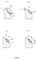
- the usual structure for these valve seats is to have a second tapered surface (valve seat surface) which is conventionally at a 90° opening angle with respect to the valve stem and, continuing from this on the upstream and downstream sides are a first tapered surface (upstream side guide tapered surface) and third tapered surface (downstream guide tapered surface) conventionally formed at opening angles of 30 and 120° respectively.
- a 30° cutting tool, 90° cutting tool and 120° cutting tool is affixed concentrically in a cutting tool holder, and first, the 30° and 120° tools are advanced to shape the first and the third tapered surfaces simultaneously, and then, both tools are drawn back 0.2 to 1 mm, and in this state, the 90° tool is advanced to shape the second tapered surface.
- valve seats since the foregoing valve seats must be highly wear resistant to stand up to the seating of the valves, further highly heat resistant to withstand the high gas temperatures, and evince good sealing properties, they are composed of a metal layer that is different from the metal used for the cylinder head stock.
- the methods of shaping this heterogeneous metal layer include press fitting the seat rings made from a sintered ferrous material around the valve openings, or passing electric current through them while applying pressure to the seat rings to weld them in place (see Japan Patent Application Disclosures Hei 5-336657 and Hei 4-114220). After the layer of heterogeneous metal is formed using either of the foregoing methods, it is necessary to use a cutting tool to shape the valve seat surface, the guide tapered surface, etc., as was described above.
- a guide tapered surface is shaped into the side of the foregoing valve seat surface that is closer to the mating surface with the cylinder block that serves as a guide for the inflow of intake air and the expulsion of exhaust gases, and in response to recent demand for higher engine output, there is demand for a valve seat structure which increases the exchange efficiency of the foregoing air intake and exhaust gases.
- valve seat structure in the prior art using the 90° tool to shape the second tapered surface (valve seat surface), there is a problem with nicks or cracks developing during the machining process which may cause the product to be defective.
- pitching of the foregoing tool itself could occur, and there is the further problem of the resulting short tool longevity.
- valve seat structure as indicated above which always assures the production of reliable valve seats and simultaneously improves the machining accuracy of tapered surfaces on a plurality of materials.
- this objective is solved for a method of manufacturing a valve seat structure as indicated above in that prior to said machining step a fourth tapered surface is provided on a side closer to the mating surface with the cylinder block, whereby the opening angle of this guide tapered surface is larger than the opening angles of the remaining tapered surfaces.
- this further objective is solved for a valve seat structure as indicated above by a fourth tapered surface positioned on a side closer to the mating surface with said cylinder block adjacent said third tapered surface and that the opening angle of said fourth tapered surface is larger than the opening angles of all remaining tapered surfaces with respect to an axis of a valve shaft.
- valve seat surface By providing said valve seat surface in a position where only said seat ring or layer material is present, nicking or pitching during the machining process of said tapered surface is eliminated.
- said first tapered surface and/or said third tapered surface has axial lengths comprising a first or third length only occupying said seat ring or layer material and a second or fourth length only occupying said cylinder head material, whereby said second and/or fourth lengths occupy more than 50% of said axial lengths.
- Said seat ring or layer may be attached by using a welding method by applying pressure of an electrical currant to said seat ring or layer, or a laser clad method or a molding injection method.
- valve seat material is triangularly shaped, one corner of which is directed to said cylinder head.
- a second guide tapered surface with an opening angle greater than said guide tapered surface is formed, so that when a valve lifts, the intake air flow traversing the gap between the valve's sealing surface and the valve seat is decelerated due to the second guide tapered surface with a larger angle, thereby causing the intake air not to separate from the inside concave surface of the combustion chamber and be smoothly introduced therein.
- the forming of the second guide tapered surface also smoothes the flow of the exhaust gases and thereby improves the gas exchange efficiency.
- the boundary between the cylinder head stock and the layer of heterogeneous metal for the valve seat is located inside the guide tapered surface or in the second guide tapered surface, and moreover, the area for one or the other of the foregoing layer of heterogeneous metal or cylinder stock material is set to exceed 50% of the area of said tapered surface.
- the area of one or the other of the foregoing layer of heterogeneous metal or the cylinder head stock exceeds 50% of the area of said guide tapered surface; in other words, one or the other of the areas is set to be larger, and the cutting conditions for the tool are set based upon the material occupying the larger area, thereby enabling the machining accuracy to be improved, and the pitching of the tool to be prevented.
- the shaping of the second guide tapered surface improves the gas exchange efficiency, and the machining accuracy is improved by making the area of one or the other metal larger.
- Figures 1 through 9 will be used to explain the valve seat structure on a cylinder head of a first embodiment.
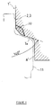
- Figure 1 is a sectional view showing a valve seat area
- Figures 2 through 6 are process diagrams to explain the machining process of the valve seat
- Figures 7 (a)-(c) show the cutting tool holder used for the respective foregoing cutting methods
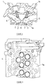
- Figures 8 and 9 show sectional and bottom views of a cylinder head.
- 1 represents a die cast aluminum cylinder head evincing the valve seats structure of this embodiment, and an omitted cylinder block is present beneath said cylinder heads 1 bottom mating surface (the side that mates with the cylinder unit) 1a.
- a cylinder head cover is attached to the top mating surface 1b.
- Concave combustion areas 1c that compose the combustion chamber are shaped on the bottom mating surface 1a of the cylinder head 1.
- Three air intake valve openings 2 and two exhaust valve openings 3 are shaped in each of said concave areas 1c. These air intake valve openings 2 are connected by an air intake port 4 to the wall on one side of the cylinder head, and the exhaust valve openings are connected by the exhaust port 5 to the other side wall.
- valve seat material layer of heterogeneous metal
- a second tapered surface (valve seat surface) T2 with an opening angle of 90° with respect to the axis C of the valve shaft is shaped into said valve seat material 20, and, in addition, a first tapered surface T1 on the upstream side with an opening angle of 30°, and a third tapered surface (guide tapered surface) located on the downstream side with an opening angle of 120°, further, continuing from this third tapered surface T3 is a fourth tapered surface (second guide tapered surface) T4 with an opening angle of 140°. whereby an opening angle of up to 180° is also possible.
- valve seat material 20 consists of seat rings that have been pressed into the valve openings and welded into place by heating with an electrical current. This feature causes the formation of an intermediate layer 21 of plastically deformed cylinder head stock between the valve seat material 20 and the cylinder head stock.
- the entirety of the foregoing second tapered surface T2 is composed of the foregoing valve seat material 20.
- the foregoing first and third tapered surfaces T1, T3 just a small part is composed of the valve seat material 20, while the remainder (most) is composed of the cylinder head stock.
- the ratios A2/A, A2'/A' of the inside circumferential area composed of the cylinder head stock for the foregoing first tapered surface T1 and third tapered surface T3 to the entire inside circumferential area of these tapered surfaces exceeds 50%, and indeed, is approximately 90%.
- the ratios A1/A, A1'/A' of the area of the seat material 20 that occupies the total inside circumferential area of the first and third tapered surfaces T1, T3 is kept low.
- the width-dimensions of the valve seat material A1, A1' are under 1 mm, specifically, they range approximately from 0.3 to 0.5 mm so that the thickness A3 of the valve seat material is about 0.5 mm.
- the cross-section of the foregoing valve seat material is approximately triangular, but as will be described later, this feature results from using the welding method as the method of manufacture.
- a machined relief surface a ' with a diameter larger than that of the guide machined surface a , which corresponds to the rotational diameter of the tool used on the a fourth tapered surface (second guide tapered surface) T4 that comprises an opening angle greater than that of the third tapered surface T3.
- the opening angle for T4 is set at 140°
- the machined surface a ' is set to be about 0.6 mm larger than the diameter of the machined surface a for the 120° C opening angle (see Figure 1).
- the fourth tapered surface (second guide tapered surface) T4 and the machined relief surface a ' it is possible to prevent the formation of nicks and cracks while machining the foregoing valve seat material 20, and this feature further smoothes the inflow of intake air and outflow of exhaust gases to improve the gas exchange efficiency.
- the opening angle of T4 is set at 140°, it is also possible to set it up to 180°.
- the method of this invention involves an attachment process, preliminary machining process, and a machining process, and these will be described in order below.
- a flat surface and an a tapered attachment area 1b are shaped around the valve openings in the cylinder head stock 1' that was manufactured by aluminum die casting.
- seat rings 22 (see Figure 2(a)), which are made from a sintered ferrous material with a Cu-plated surface treatment, are prepared. When viewed in horizontal cross-section, these seat rings 22 are triangular with an apex 22a. By using this apex area 22a, it is possible to increase the surface pressure on the cylinder head stock during the pressing operation to facilitate the plastic deformation of said stock.
- This press jig 23 roughly consists of a rod-shaped guide bar 24 to which an axially movable electrode 25 is attached, so that electricity can be passed through said electrode 25 while pressure is being applied to the seat ring 22.
- an end mill 11 is used on the seat ring areas 22 that were attached in the foregoing manner, to create the fourth tapered surface (second guide tapered surface) T4 at an opening angle of 140°, and the machined relief surface a ' which is about 0.6 mm larger than the diameter of the machined surface a for the 120° machined surface (see Figure 3(a), 3(b) and Figure 4).
- the machined relief surface a ' which is about 0.6 mm larger than the diameter of the machined surface a for the 120° machined surface (see Figure 3(a), 3(b) and Figure 4).
- the cutting tool holder 15 used in this machining process comprises a main shaft apparatus (not shown) which is supported so that it may freely advance and recede, and a motor which rotates it.
- Cutting bits with the required angle are installed into said cutting tool holder 15: a 30° cutting bit 16, a 120° cutting bit 17, and a 90° cutting bit 18.
- Said 90° bit 18 comprises a feed member 19 which can move it in the axial direction with respect to the foregoing tool holder 15.
- each of the cutting bits are CBN bits.
- the cutting tool holder 15 is inserted into the openings 2, 3 of the cylinder head stock 1' with the foregoing feed member 19 in the retracted position, and initial plunge cutting is performed by advancing the 30° bit 16 and 120° bit 17 which simultaneously shapes the first tapered surface (the guide taper surface on the upstream side) T1, and the third tapered surface (the guide tapered surface on the downstream side) T3 (see Figure 3(c)). After this plunge cut, both bits 16, 17 are retracted 0.2mm (see Figure 5).
- the foregoing feed member 19 is advanced and the 90° bit 18 is used to perform a traverse cutting operation which shapes the second tapered surface T2.
- the valve seat areas T are shaped into the above mentioned cylinder head 1 (see Figure 1, Figure 3(d)).
- the valve structure according to the present embodiment forms the forth tapered surface T4 in a preliminary stage to the machining of the first through third tapered surfaces T1-T3, hence no vibrations are transmitted to the 90° cutting bit 18 that would have normally resulted from contact with the machined surface from the 120° bit 17.
- nicks and cracks to the valve seat material 20 can be prevented, and, by extension, the yields of the product and bit longevity can be thereby improved.
- the fourth tapered surface T4 is shaped as a continuation from the foregoing third tapered surface T3, for example on the air intake valve side, the intake air flowing through the gap between the seal surface and the valve seat surface when the valve is lifted undergoes flow deceleration by an amount corresponding to the magnitude of the opening angle of the foregoing fourth tapered surface T4, and this feature inhibits the diversion of the air from the inside wall of the combustion chamber, resulting in a smoother flow of intake air. Also, on the exhaust valve side, the widening caused by the foregoing fourth tapered surface T4 smoothes the flow of the exhaust gases between the valve seat surface and the seal surface, resulting in improved efficiency in gas exchange.
- the machining conditions can be set appropriately for the cylinder head stock (which occupies the vast proportion of the area), which feature simplifies the bit selection and the cutting conditions for the machining of differing materials, and improves the machining accuracy, and in addition, prevents pitching of the bits and extends their longevity.
- the present embodiment holds the ratio of the ferrous alloy seat material 20 to a low proportion, thereby diminishing the foregoing heat stress, and making separation less likely.
- the example explained the positioning of the interface area 26 between the cylinder head stock 1' and the valve seat material 20 inside the third tapered surface T3, but the invention is not limited to this condition. As is shown by the broken line in Figure 1, it is also possible to position the border 26' of the valve seat material 20' inside the fourth tapered surface T4. By so doing, the entire surface of the third tapered surface T3 is composed of the valve seat material 20'.
- This type of structure allows preventing nicking during taper cutting with CBN bits, and extends bit longevity. Since an end mill was used to perform the machining for the foregoing fourth tapered surface T4, there is no great problem with nicking.
- the above example used a welding method involving the application of pressure and electrical current to bond the layer of heterogeneous metal, but the method of this invention may be equally well applied to using the laser clad method or the molten injection method for forming the layer of heterogeneous metal.
- a second guide tapered surface is shaped with a larger opening angle on the side of the mating surface with the cylinder block from the guide tapered surface, thus smoothing the air intake and exhaust gas flows to improve the gas exchange efficiency and to contribute to improved engine output.
- the border between the cylinder head stock and the heterogeneous metal layer for the valve seat is positioned inside the guide tapered surface or second guide tapered surface, and moreover, either the cylinder head stock or the heterogeneous metal layer of the valve seat occupies more than 50% of the area of one of said tapered surfaces, and, according to a further embodiment, the foregoing boundary layer is positioned in the guide tapered surface, and in addition either of the heterogeneous metal layer or the cylinder head stock is made to occupy more than 50% of the area of said guide tapered surface, so that the bit selection and the cutting conditions for the machining can be set for the material that occupies most of the area. This feature improves the machining accuracy and prevents the pitching of the bits.
- the heterogeneous metal layer is formed using pressure and current induced heat welding, wherein the shaping of a second guide tapered surface improves the gas exchange efficiency, and selecting either stock type with a larger area improves the machining accuracy.
Landscapes
- Engineering & Computer Science (AREA)
- Mechanical Engineering (AREA)
- General Engineering & Computer Science (AREA)
- Cylinder Crankcases Of Internal Combustion Engines (AREA)
- Pressure Welding/Diffusion-Bonding (AREA)
Applications Claiming Priority (3)
| Application Number | Priority Date | Filing Date | Title |
|---|---|---|---|
| JP28217/95 | 1995-02-16 | ||
| JP2821795 | 1995-02-16 | ||
| JP02821795A JP3373317B2 (ja) | 1995-02-16 | 1995-02-16 | シリンダヘッドのバルブシート部構造 |
Publications (2)
| Publication Number | Publication Date |
|---|---|
| EP0727565A1 true EP0727565A1 (fr) | 1996-08-21 |
| EP0727565B1 EP0727565B1 (fr) | 2000-05-17 |
Family
ID=12242471
Family Applications (1)
| Application Number | Title | Priority Date | Filing Date |
|---|---|---|---|
| EP96102384A Expired - Lifetime EP0727565B1 (fr) | 1995-02-16 | 1996-02-16 | Une structure de siège de soupape et une méthode pour sa réalisation |
Country Status (4)
| Country | Link |
|---|---|
| US (1) | US5787853A (fr) |
| EP (1) | EP0727565B1 (fr) |
| JP (1) | JP3373317B2 (fr) |
| DE (1) | DE69608329T2 (fr) |
Cited By (6)
| Publication number | Priority date | Publication date | Assignee | Title |
|---|---|---|---|---|
| WO1998028523A1 (fr) * | 1996-12-21 | 1998-07-02 | Unova U.K. Limited | Procede d'installation de bagues de sieges de soupapes et appareil d'installation |
| FR2818175A1 (fr) * | 2000-12-19 | 2002-06-21 | Renault | Procede de fabrication d'un conduit interieur d'une culasse |
| EP1533485A3 (fr) * | 2003-11-11 | 2009-01-07 | HONDA MOTOR CO., Ltd. | Soupape d'admission / échappement de moteur à combustion interne et dispositif d'étanchéité |
| FR2946907A1 (fr) * | 2009-06-19 | 2010-12-24 | Peugeot Citroen Automobiles Sa | Procede de fabrication d'une culasse munie d'une paroi de guidage d'ecoulement au niveau d'un siege de soupape |
| CN109483032A (zh) * | 2017-09-11 | 2019-03-19 | 本田技研工业株式会社 | 焊接部形成结构和金属部件的接合方法 |
| WO2020219273A1 (fr) * | 2019-04-26 | 2020-10-29 | Caterpillar Inc. | Pièce rapportée de siège de soupape à double bombement à surface d'assise constituée d'un matériau de revêtement dur |
Families Citing this family (17)
| Publication number | Priority date | Publication date | Assignee | Title |
|---|---|---|---|---|
| DE60010813T2 (de) * | 1999-08-06 | 2004-10-07 | Honda Motor Co Ltd | Diffusionsverbindungsverfahren |
| CA2333933C (fr) * | 2000-02-04 | 2004-09-21 | Hitachi, Ltd. | Soupape munie d'un alliage resistant a la corrosion et a l'usure, et appareils se servant de ladite soupape |
| DE10255447A1 (de) * | 2002-11-28 | 2004-06-24 | Daimlerchrysler Ag | Ventilsitz und Verfahren zur Herstellung eines Ventilsitzes |
| DE102007031464A1 (de) * | 2006-07-17 | 2008-01-24 | Alstom Technology Ltd. | Dampfeinlassventil einer Dampfturbine |
| US20090044780A1 (en) * | 2007-06-25 | 2009-02-19 | Soverns Laura M | Special improved durability engine device for use with stationary power generation systems |
| NL2001869C2 (nl) * | 2008-08-01 | 2010-02-02 | Stichting Materials Innovation | Cilinderkop met klepzitting alsmede werkwijze voor het vervaardigen daarvan. |
| US9435454B2 (en) * | 2009-02-23 | 2016-09-06 | George H Blume | Fluid end with carbide valve seat and adhesive dampening interface |
| US8662045B2 (en) * | 2009-08-03 | 2014-03-04 | GM Global Technology Operations LLC | Cylinder head assembly for an internal combustion engine |
| US20110100316A1 (en) * | 2009-11-05 | 2011-05-05 | Gm Global Technology Operations, Inc. | Cylinder Head Assembly For An Internal Combustion Engine and Method of Manufacture |
| US8672018B2 (en) * | 2012-08-20 | 2014-03-18 | GM Global Technology Operations LLC | Cylinder head and method |
| JP5897712B2 (ja) | 2012-11-22 | 2016-03-30 | 株式会社エフ・シー・シー | 一体部材の製造方法及び一体部材 |
| US10202938B2 (en) | 2013-07-09 | 2019-02-12 | Briggs & Stratton Corporation | Welded engine block for small internal combustion engines |
| CN105556103B (zh) | 2013-07-09 | 2018-08-10 | 布里格斯斯特拉顿公司 | 小型内燃机的焊接发动机缸体 |
| US9581106B2 (en) | 2013-07-09 | 2017-02-28 | Briggs & Stratton Corporation | Welded engine block for small internal combustion engines |
| US10844758B2 (en) * | 2019-01-22 | 2020-11-24 | Caterpillar Inc. | Engine and gas exchange valve with under-head fillet contoured for chordal stress mitigation |
| WO2021176335A1 (fr) | 2020-03-02 | 2021-09-10 | Briggs & Stratton, Llc | Moteur à combustion interne à entretien d'huile réduit |
| US11473456B2 (en) * | 2020-09-15 | 2022-10-18 | GM Global Technology Operations LLC | Cylinder head valve seat with high thermal conductivity and multiple material cross-section |
Citations (8)
| Publication number | Priority date | Publication date | Assignee | Title |
|---|---|---|---|---|
| EP0064367A2 (fr) * | 1981-05-04 | 1982-11-10 | Park-Ohio Industries, Inc. | Procédé pour le chauffage inductif d'insertions de siège de soupapes |
| EP0092683A1 (fr) * | 1982-04-22 | 1983-11-02 | FIAT AUTO S.p.A. | Méthode de fabrication d'un siège de soupape pour une culasse d'un moteur endothermique et moteur pourvu de sièges de soupape fabriqués par cette méthode |
| EP0228282A2 (fr) * | 1985-12-25 | 1987-07-08 | Toyota Jidosha Kabushiki Kaisha | Culasse en aluminium avec siège-soupape formé intégralement par une couche de cuivre et une couche de base |
| DE3613299A1 (de) * | 1986-04-19 | 1987-10-22 | Opel Adam Ag | Ventil, insbesondere auslassventil fuer verbrennungsmotoren |
| US4831976A (en) * | 1987-02-02 | 1989-05-23 | General Motors Corporation | Engine with valve seat inserts and method of retaining |
| US4896638A (en) * | 1988-12-07 | 1990-01-30 | Ford Motor Company | Fabricating internal combustion engine cylinder heads with close tolerance internal surfaces |
| DE3928597A1 (de) * | 1989-08-30 | 1991-03-07 | Ingo Werner Scheer | Werkzeug zur spanabhebenden bearbeitung von aus metall bestehenden werkstuecken |
| DE4322435A1 (de) * | 1993-07-06 | 1995-01-12 | Daimler Benz Ag | Verfahren zum Bearbeiten von Ventilsitzringen |
-
1995
- 1995-02-16 JP JP02821795A patent/JP3373317B2/ja not_active Expired - Fee Related
-
1996
- 1996-02-16 EP EP96102384A patent/EP0727565B1/fr not_active Expired - Lifetime
- 1996-02-16 US US08/601,287 patent/US5787853A/en not_active Expired - Fee Related
- 1996-02-16 DE DE69608329T patent/DE69608329T2/de not_active Expired - Fee Related
Patent Citations (8)
| Publication number | Priority date | Publication date | Assignee | Title |
|---|---|---|---|---|
| EP0064367A2 (fr) * | 1981-05-04 | 1982-11-10 | Park-Ohio Industries, Inc. | Procédé pour le chauffage inductif d'insertions de siège de soupapes |
| EP0092683A1 (fr) * | 1982-04-22 | 1983-11-02 | FIAT AUTO S.p.A. | Méthode de fabrication d'un siège de soupape pour une culasse d'un moteur endothermique et moteur pourvu de sièges de soupape fabriqués par cette méthode |
| EP0228282A2 (fr) * | 1985-12-25 | 1987-07-08 | Toyota Jidosha Kabushiki Kaisha | Culasse en aluminium avec siège-soupape formé intégralement par une couche de cuivre et une couche de base |
| DE3613299A1 (de) * | 1986-04-19 | 1987-10-22 | Opel Adam Ag | Ventil, insbesondere auslassventil fuer verbrennungsmotoren |
| US4831976A (en) * | 1987-02-02 | 1989-05-23 | General Motors Corporation | Engine with valve seat inserts and method of retaining |
| US4896638A (en) * | 1988-12-07 | 1990-01-30 | Ford Motor Company | Fabricating internal combustion engine cylinder heads with close tolerance internal surfaces |
| DE3928597A1 (de) * | 1989-08-30 | 1991-03-07 | Ingo Werner Scheer | Werkzeug zur spanabhebenden bearbeitung von aus metall bestehenden werkstuecken |
| DE4322435A1 (de) * | 1993-07-06 | 1995-01-12 | Daimler Benz Ag | Verfahren zum Bearbeiten von Ventilsitzringen |
Cited By (10)
| Publication number | Priority date | Publication date | Assignee | Title |
|---|---|---|---|---|
| WO1998028523A1 (fr) * | 1996-12-21 | 1998-07-02 | Unova U.K. Limited | Procede d'installation de bagues de sieges de soupapes et appareil d'installation |
| US6259054B1 (en) | 1996-12-21 | 2001-07-10 | Unova U.K. Limited | Method of fitting a valve seating ring and an apparatus therefor |
| FR2818175A1 (fr) * | 2000-12-19 | 2002-06-21 | Renault | Procede de fabrication d'un conduit interieur d'une culasse |
| EP1533485A3 (fr) * | 2003-11-11 | 2009-01-07 | HONDA MOTOR CO., Ltd. | Soupape d'admission / échappement de moteur à combustion interne et dispositif d'étanchéité |
| US7779807B2 (en) | 2003-11-11 | 2010-08-24 | Honda Motor Co., Ltd. | Intake/exhaust valve and its seal for internal combustion engine |
| FR2946907A1 (fr) * | 2009-06-19 | 2010-12-24 | Peugeot Citroen Automobiles Sa | Procede de fabrication d'une culasse munie d'une paroi de guidage d'ecoulement au niveau d'un siege de soupape |
| CN109483032A (zh) * | 2017-09-11 | 2019-03-19 | 本田技研工业株式会社 | 焊接部形成结构和金属部件的接合方法 |
| CN109483032B (zh) * | 2017-09-11 | 2021-06-11 | 本田技研工业株式会社 | 焊接部形成结构和金属部件的接合方法 |
| WO2020219273A1 (fr) * | 2019-04-26 | 2020-10-29 | Caterpillar Inc. | Pièce rapportée de siège de soupape à double bombement à surface d'assise constituée d'un matériau de revêtement dur |
| US10989321B2 (en) | 2019-04-26 | 2021-04-27 | Caterpillar Inc. | Double-crowned valve seat insert having seating surface formed of hard-facing material |
Also Published As
| Publication number | Publication date |
|---|---|
| JPH08218937A (ja) | 1996-08-27 |
| US5787853A (en) | 1998-08-04 |
| DE69608329D1 (de) | 2000-06-21 |
| EP0727565B1 (fr) | 2000-05-17 |
| DE69608329T2 (de) | 2000-09-21 |
| JP3373317B2 (ja) | 2003-02-04 |
Similar Documents
| Publication | Publication Date | Title |
|---|---|---|
| EP0727565B1 (fr) | Une structure de siège de soupape et une méthode pour sa réalisation | |
| US4819325A (en) | Method of forming electro-discharge machining electrode | |
| US4922076A (en) | Electro-discharge machining electrode | |
| US8516674B2 (en) | Solid state resistance welding for airfoil repair and manufacture | |
| US6138351A (en) | Method of making a valve seat | |
| US20150224589A1 (en) | Method for producing an arbitrary geometry on pistons of internal combustion engines | |
| CN101018642B (zh) | 焊接电极 | |
| EP0751284A1 (fr) | Culasse et procédé pour la production d'un siège soupape | |
| CN1343545A (zh) | 座面硬化的发动机阀及制造座面硬化的发动机阀的方法 | |
| US5778531A (en) | Method of manufacturing cylinder head for engine | |
| US5687685A (en) | Valve seat and method | |
| US5848579A (en) | Cylinder head for engine | |
| EP0730085B1 (fr) | Culasse et méthode pour fabriquer un siège de soupapes | |
| US5970614A (en) | Method for forming valve seats | |
| SG175121A1 (en) | Method for repairing worn valve spindles | |
| US5761806A (en) | Method of bonding valve seat | |
| JPH09141629A (ja) | ハニカム構造体押出装置 | |
| JP2004510595A (ja) | エンジン・ピストンおよびその製造 | |
| CN212495714U (zh) | 一种加工变齿厚花键复合齿内花键的精加工拉刀 | |
| KR100394173B1 (ko) | 분말야금법으로미리제작된밸브시트링의조립및마무리가공방법 | |
| JPH08218827A (ja) | シリンダヘッドのバルブシート部の加工方法 | |
| EP2162651A2 (fr) | Ameliorations de tolerance de composant de metal en poudre | |
| JPH10339117A (ja) | エンジンの肉盛りバルブシート及びその製造方法 | |
| EP1222981B1 (fr) | Procédé de fabrication d'un bloc-cylindres d'un moteur à combustion interne | |
| JPS61180633A (ja) | 内燃機関用シリンダスリ−ブの製造方法 |
Legal Events
| Date | Code | Title | Description |
|---|---|---|---|
| PUAI | Public reference made under article 153(3) epc to a published international application that has entered the european phase |
Free format text: ORIGINAL CODE: 0009012 |
|
| AK | Designated contracting states |
Kind code of ref document: A1 Designated state(s): DE FR GB IT |
|
| 17P | Request for examination filed |
Effective date: 19970220 |
|
| 17Q | First examination report despatched |
Effective date: 19980422 |
|
| GRAG | Despatch of communication of intention to grant |
Free format text: ORIGINAL CODE: EPIDOS AGRA |
|
| GRAG | Despatch of communication of intention to grant |
Free format text: ORIGINAL CODE: EPIDOS AGRA |
|
| GRAG | Despatch of communication of intention to grant |
Free format text: ORIGINAL CODE: EPIDOS AGRA |
|
| GRAH | Despatch of communication of intention to grant a patent |
Free format text: ORIGINAL CODE: EPIDOS IGRA |
|
| GRAH | Despatch of communication of intention to grant a patent |
Free format text: ORIGINAL CODE: EPIDOS IGRA |
|
| GRAA | (expected) grant |
Free format text: ORIGINAL CODE: 0009210 |
|
| AK | Designated contracting states |
Kind code of ref document: B1 Designated state(s): DE FR GB IT |
|
| PG25 | Lapsed in a contracting state [announced via postgrant information from national office to epo] |
Ref country code: IT Free format text: LAPSE BECAUSE OF FAILURE TO SUBMIT A TRANSLATION OF THE DESCRIPTION OR TO PAY THE FEE WITHIN THE PRESCRIBED TIME-LIMIT;WARNING: LAPSES OF ITALIAN PATENTS WITH EFFECTIVE DATE BEFORE 2007 MAY HAVE OCCURRED AT ANY TIME BEFORE 2007. THE CORRECT EFFECTIVE DATE MAY BE DIFFERENT FROM THE ONE RECORDED. Effective date: 20000517 Ref country code: FR Free format text: LAPSE BECAUSE OF FAILURE TO SUBMIT A TRANSLATION OF THE DESCRIPTION OR TO PAY THE FEE WITHIN THE PRESCRIBED TIME-LIMIT Effective date: 20000517 |
|
| REF | Corresponds to: |
Ref document number: 69608329 Country of ref document: DE Date of ref document: 20000621 |
|
| EN | Fr: translation not filed | ||
| PLBE | No opposition filed within time limit |
Free format text: ORIGINAL CODE: 0009261 |
|
| STAA | Information on the status of an ep patent application or granted ep patent |
Free format text: STATUS: NO OPPOSITION FILED WITHIN TIME LIMIT |
|
| 26N | No opposition filed | ||
| REG | Reference to a national code |
Ref country code: GB Ref legal event code: IF02 |
|
| PGFP | Annual fee paid to national office [announced via postgrant information from national office to epo] |
Ref country code: GB Payment date: 20040211 Year of fee payment: 9 |
|
| PGFP | Annual fee paid to national office [announced via postgrant information from national office to epo] |
Ref country code: DE Payment date: 20040226 Year of fee payment: 9 |
|
| PG25 | Lapsed in a contracting state [announced via postgrant information from national office to epo] |
Ref country code: GB Free format text: LAPSE BECAUSE OF NON-PAYMENT OF DUE FEES Effective date: 20050216 |
|
| PG25 | Lapsed in a contracting state [announced via postgrant information from national office to epo] |
Ref country code: DE Free format text: LAPSE BECAUSE OF NON-PAYMENT OF DUE FEES Effective date: 20050901 |
|
| GBPC | Gb: european patent ceased through non-payment of renewal fee |
Effective date: 20050216 |