EP0729707A2 - Method and apparatus for recirculating product in a refrigeration system - Google Patents
Method and apparatus for recirculating product in a refrigeration system Download PDFInfo
- Publication number
- EP0729707A2 EP0729707A2 EP96101131A EP96101131A EP0729707A2 EP 0729707 A2 EP0729707 A2 EP 0729707A2 EP 96101131 A EP96101131 A EP 96101131A EP 96101131 A EP96101131 A EP 96101131A EP 0729707 A2 EP0729707 A2 EP 0729707A2
- Authority
- EP
- European Patent Office
- Prior art keywords
- section
- product
- freezing
- inlet
- mix
- Prior art date
- Legal status (The legal status is an assumption and is not a legal conclusion. Google has not performed a legal analysis and makes no representation as to the accuracy of the status listed.)
- Ceased
Links
Images


Classifications
-
- A—HUMAN NECESSITIES
- A23—FOODS OR FOODSTUFFS; TREATMENT THEREOF, NOT COVERED BY OTHER CLASSES
- A23G—COCOA; COCOA PRODUCTS, e.g. CHOCOLATE; SUBSTITUTES FOR COCOA OR COCOA PRODUCTS; CONFECTIONERY; CHEWING GUM; ICE-CREAM; PREPARATION THEREOF
- A23G9/00—Frozen sweets, e.g. ice confectionery, ice-cream; Mixtures therefor
- A23G9/04—Production of frozen sweets, e.g. ice-cream
- A23G9/22—Details, component parts or accessories of apparatus insofar as not peculiar to a single one of the preceding groups
- A23G9/225—Ice-cream freezing and storing cabinets
-
- A—HUMAN NECESSITIES
- A23—FOODS OR FOODSTUFFS; TREATMENT THEREOF, NOT COVERED BY OTHER CLASSES
- A23B—PRESERVATION OF FOODS, FOODSTUFFS OR NON-ALCOHOLIC BEVERAGES; CHEMICAL RIPENING OF FRUIT OR VEGETABLES
- A23B2/00—Preservation of foods or foodstuffs, in general
- A23B2/40—Preservation of foods or foodstuffs, in general by heating loose unpacked materials
- A23B2/42—Preservation of foods or foodstuffs, in general by heating loose unpacked materials while they are progressively transported through the apparatus
-
- A—HUMAN NECESSITIES
- A23—FOODS OR FOODSTUFFS; TREATMENT THEREOF, NOT COVERED BY OTHER CLASSES
- A23B—PRESERVATION OF FOODS, FOODSTUFFS OR NON-ALCOHOLIC BEVERAGES; CHEMICAL RIPENING OF FRUIT OR VEGETABLES
- A23B2/00—Preservation of foods or foodstuffs, in general
- A23B2/80—Freezing; Subsequent thawing; Cooling
- A23B2/805—Materials not being transported through or in the apparatus with or without shaping, e.g. in the form of powders, granules or flakes
-
- A—HUMAN NECESSITIES
- A23—FOODS OR FOODSTUFFS; TREATMENT THEREOF, NOT COVERED BY OTHER CLASSES
- A23G—COCOA; COCOA PRODUCTS, e.g. CHOCOLATE; SUBSTITUTES FOR COCOA OR COCOA PRODUCTS; CONFECTIONERY; CHEWING GUM; ICE-CREAM; PREPARATION THEREOF
- A23G9/00—Frozen sweets, e.g. ice confectionery, ice-cream; Mixtures therefor
- A23G9/04—Production of frozen sweets, e.g. ice-cream
- A23G9/14—Continuous production
- A23G9/16—Continuous production the products being within a cooled chamber, e.g. drum
-
- A—HUMAN NECESSITIES
- A23—FOODS OR FOODSTUFFS; TREATMENT THEREOF, NOT COVERED BY OTHER CLASSES
- A23G—COCOA; COCOA PRODUCTS, e.g. CHOCOLATE; SUBSTITUTES FOR COCOA OR COCOA PRODUCTS; CONFECTIONERY; CHEWING GUM; ICE-CREAM; PREPARATION THEREOF
- A23G9/00—Frozen sweets, e.g. ice confectionery, ice-cream; Mixtures therefor
- A23G9/04—Production of frozen sweets, e.g. ice-cream
- A23G9/22—Details, component parts or accessories of apparatus insofar as not peculiar to a single one of the preceding groups
- A23G9/224—Agitators or scrapers
-
- A—HUMAN NECESSITIES
- A23—FOODS OR FOODSTUFFS; TREATMENT THEREOF, NOT COVERED BY OTHER CLASSES
- A23G—COCOA; COCOA PRODUCTS, e.g. CHOCOLATE; SUBSTITUTES FOR COCOA OR COCOA PRODUCTS; CONFECTIONERY; CHEWING GUM; ICE-CREAM; PREPARATION THEREOF
- A23G9/00—Frozen sweets, e.g. ice confectionery, ice-cream; Mixtures therefor
- A23G9/04—Production of frozen sweets, e.g. ice-cream
- A23G9/22—Details, component parts or accessories of apparatus insofar as not peculiar to a single one of the preceding groups
- A23G9/228—Arrangement and mounting of control or safety devices
-
- F—MECHANICAL ENGINEERING; LIGHTING; HEATING; WEAPONS; BLASTING
- F28—HEAT EXCHANGE IN GENERAL
- F28F—DETAILS OF HEAT-EXCHANGE AND HEAT-TRANSFER APPARATUS, OF GENERAL APPLICATION
- F28F19/00—Preventing the formation of deposits or corrosion, e.g. by using filters or scrapers
- F28F19/008—Preventing the formation of deposits or corrosion, e.g. by using filters or scrapers by using scrapers
Definitions
- This invention relates to apparatus and methods used in the continuous production of edible product in refrigeration systems, and more particularly, to methods and apparatus for recirculating processed frozen product through outlet sections of the apparatus and reprocessing the product during selected operations of the system.
- Conventional refrigeration systems used in the production of frozen desserts and the like typically include a freezing cylinder that receives unfrozen product mix from an inlet section and provides processed product through an outlet section to a filler. In order to process the product mix, the freezing cylinder is initially filled with unfrozen mix. The refrigeration system surrounding the freezing cylinder is started. When the freezing cylinder is filled, a dasher assembly in the freezing cylinder is started so that blades attached to the dasher assembly scrape the freezing cylinder wall to introduce ice crystals formed on the cylinder wall with the product mix.
- the viscosity of the product mix increases as its temperature decreases and ice crystals are scraped from the freezing cylinder wall.
- the increased viscosity is detected by monitoring the load on the dasher motor.
- the dasher motor-load rises to a predetermined level, forward flow of the dessert mix begins.
- dessert mix and air is supplied under pressure into the freezing cylinder.
- frozen dessert from the freezing cylinder exits to the outlet section and then to processing equipment downstream of the freezing cylinder.
- the frozen dessert is either diverted for reconditioning or is destroyed when forward flow of the system is interrupted and then restarted. This may be necessitated, for example, when intervention is required for correcting problems with subsequent packaging stations or with other equipment downstream from the freezing system. In some instances, the product line must be shut down completely and restarted, again resulting in unacceptable loss of product.
- a freezing system that includes a freezing section having a freezing section inlet and an outlet that processes product mix, an inlet section coupled with the freezing section inlet, an outlet or discharge section coupled with the freezing section outlet and a recirculation section.
- the recirculation section is coupled with the outlet section and the freezing section inlet and, when operating in a selected mode such as a startup mode, recycles processed product after it has been drawn through the outlet section back to the freezing section inlet.
- the inlet section provides product mix to the freezing section which is processed by the freezing section.
- the processed product is then supplied via the outlet section to downstream locations.
- approximately 100 percent of the product mix may be recirculated and reprocessed by the freezing section of the system.
- the product density and viscosity of the product mix may be controlled when in the recirculation mode.
- the freezing section and components in the outlet section are filled with food product which is recirculated until a desired temperature is attained in the outlet section of the system.
- processed product may be recirculated from the outlet section back to the freezing section inlet in other operating conditions, such as, for example, when downstream packaging equipment is rendered inoperative. In this way, significant amounts of wasted ice-cream are eliminated.
- the inlet section of the system includes a product mix pump that supplies product mix to the freezing section inlet so that a desired pressure is maintained in the freezing section.
- the outlet section likewise includes a product discharge pump that controls product flow through the freezing cylinder.
- the product mix pump may be implemented as a low cost centrifugal-type pump when the product discharge pump is located in close relation to the freezing section outlet.
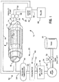
- FIG. 1 is a block diagram representation of a refrigeration system for processing frozen edible product according to the present invention.
- FIG. 2 is an electrical block diagram representation of various components in the system shown in FIG. 1.
- FIG. 3 is a logical flow diagram for operation of a refrigeration system in a FILL mode according to the present invention.
- FIG. 4 depicts a logical flow diagram for operation of a refrigeration system in a PROCESS or FREEZE mode.
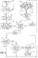
- FIG. 5 is a logical flow diagram for operation of a refrigeration system in a HOLD mode.
- the present invention relates to a refrigeration system for processing frozen edible product that includes a freezing section, an inlet section, an outlet or product discharge section, and a recirculation section.
- the recirculation section selectively recycles processed product by passing the product through at least a portion of the outlet section and returning the product back to the freezing section for reprocessing.
- This arrangement enables cooling of the outlet section components while recycling the processed product, particularly during startup of the system or at another desired time, to avoid waste of processed product. In this way, the need for reworking the product is eliminated. Thereafter, processed product may be discharged to further stations.
- the system is intended for particular use in connection with processing frozen or semi-frozen dessert products such as ice-cream, or other frozen dairy products which are provided as a product mixture and typically aerated to achieve a desired consistency when processed.
- frozen or semi-frozen dessert products such as ice-cream, or other frozen dairy products which are provided as a product mixture and typically aerated to achieve a desired consistency when processed.
- the system may be utilized in other applications where various components of a refrigeration system must be brought to a selected temperature prior to operation of the system with appropriate modification.
- the term "frozen product” is used in the broadest sense herein and refers to any product that is processed by refrigeration.
- FIG. 1 is a block diagram of a refrigeration system 10 having a recirculation arrangement 12 according to the present invention.
- the refrigeration system 10 includes a freezing cylinder 14 surrounded by refrigeration apparatus 16 as will be generally known to those skilled in the art.
- the freezing cylinder 14 includes a freezing cylinder inlet 18 that receives unprocessed product mix from an inlet section 20.
- the freezing cylinder 14 also includes a dasher element shown schematically as element 22 disposed within the freezing cylinder.
- the freezing cylinder is filled with product mix.
- the dasher element 22 is then rotated by a dasher motor (denoted as numeral 24 in FIG. 2) to stir the product mix contained in the freezing cylinder while the product is cooled.
- the dasher element 22 also scrapes ice crystals from the interior surface of the freezing cylinder so that the viscosity of the product is increased as will be understood by those skilled in the art.
- Processed frozen product is thereafter available via a freezing cylinder outlet 26 at an outlet section 28. In this way, the freezing cylinder processes the edible product.
- the inlet section 20 includes a product mix tank 30 which supplies product mix through a tank shutoff valve 32 to conduit denoted by a line 34.
- the product mix is provided on line 34 to a mix pump 36 and thereafter to a mix flow meter 38 via a line 40.
- the mix flow meter 38 may be implemented as a mass flow meter which provides appropriated sensing signals (as explained below) so that the flow of product mix may be closely monitored.
- the product mix is thereafter provided to a preaerator 42 via conduit denoted by a line 44.
- the preaerator 42 also receives a selected amount of air which is metered thereto from an air input line 46.
- the preaerator operates in a known fashion to mix the selected amount of air with the product mix.
- the aerated product mix or overrun is provided via conduit denoted by a line 48 to a pressure transducer 50 that senses the input line pressure.
- the product mix is then applied through a T-type connection 52 via a line 54 and thereafter to the inlet 18 of the freezing cylinder. In this way, the freezing cylinder pressure is controlled.
- the discharge section 28 also includes conduit represented by a line 56 which receives exiting product provided the freezing cylinder outlet 26.
- the frozen or processed product passes through conduit 56 under control of an output or product discharge pump 58.
- the product discharge pump 58 is preferably a positive displacement type pump that is operated in response to a variable speed drive to control the product mix flow through the freezing cylinder 14 and the discharge section.
- the processed product is then supplied through conduit shown as an output line 60 to a three-way divert valve 62.
- other similar valve systems may be used in place of the three-way divert valve 62 such as, for example, two single-seat valves.
- the recirculation arrangement 12 includes the divert valve 62 which selectively diverts the frozen product to a recirculation conduit 64.
- the recirculation conduit 64 is coupled with the freezing cylinder inlet 18 via the T-connection 52 at its other end.
- the processed product may selectively be recycled back to the freezing cylinder inlet 18 when desired such as, for example, during a startup operation of the system.
- the divert valve 62 may be set to supply the frozen product to further processing stations via conduit represented by a line 66.
- the frozen product may be supplied to a filler processing station 68.
- other ingredients may be added to the frozen product with an ingredient filler prior to introduction to the filler station 68 as will be understood by those skilled in the art.
- the recirculation arrangement is located upstream of the filler.
- the mix pump 36 may be implemented as a centrifugal pump. This arrangement significantly reduces the overall cost of the system.
- the mix flow meter 38 is utilized to monitor the flow of the product mix so that appropriate compensation may be provided for any slippage due to the pressure differential between the input and output of the mix pump 36.
- the product discharge pump 58 is a positive displacement pump preferably located in close proximity to the freezing cylinder outlet 26.
- the mix pump 28 may also be implemented as a positive displacement pump when greater precision in the operation of the system is desired.
- This embodiment eliminates the necessity for the mix flow meter 30 in the input section since adequate information signals relating to product mix flow pressure may be obtained from signals provided by the positive displacement pump.
- FIG. 2 is an electrical block diagram illustrating a preferred control scheme for the freezing system 10.
- the freezing system 10 may operate under control of a electronic programmable logic controller 70.
- the electronic controller 70 receives dasher motor load, freezing cylinder temperature, inlet section pressure, mix flow meter and other information input signals as shown at the left of FIG. 2.
- the electronic controller 70 operates in a logical fashion to provide a mix pump control signal on a line 72, a tank shut-off valve control signal on a line 74, a product mix flow meter control signal on a line 76, an air mass flow control signal on a line 78, a freezing system control signal on a line 80, a dasher motor control signal on a line 82, a product discharge pump control signal on a line 84, and a recirculation divert valve control signal on a line 86.
- the signal on the line 74 to the tank shut-off valve enables product mix flow from the mix tank supply.
- the signal on line 78 is provided in response to the mix flow meter input information signals and pressure input signals provided to the electronic controller 70 and controls an air mass flow controller 90.
- the air mass flow controller provides via line 46 a desired air quantity to the pre-aerator so that overrun of the product mix is controlled.
- the controller 70 may process an output signal indicative of overrun pressure from the mix pump to provide the control signal on line 78.
- the signals on lines 72 and 84 control operation of the product mix pump and product discharge pump, respectively.
- the signal provided to the mix pump on line 72 controls the freezing cylinder pressure.
- the controller 70 provides the signal on line 84 based on the mix flow meter and inlet section pressure signals to control the mix flow rate through the system.
- the product discharge pump is actuated by a variable speed drive to closely control mix flow rate.
- the signal on line 80 controls operation of refrigeration apparatus 16 surrounding the freezing cylinder.
- the signal on line 86 controls operation of the recirculation divert valve.
- FIG. 3 is a logical flow diagram depicting the sequence of operation for a FILL cycle of the freezing system 10.
- the system begins at a block 100 and then advances to a decision block 102 and determines whether appropriate input information is provided to the system to initiate a FILL operation. If yes, the system advances to a block 104 and provides appropriate control signals to actuate the mix pump.
- the mix pump is actuated so that it ramps up to a desired setpoint. This is determined based on information signals received from the mix flow meter.
- the product discharge pump is also initiated at a predetermined speed.
- the system then advances to a next block 106 where the tank shut-off valve 32 is opened.
- air is metered into the input line and is rationed in accordance with the output from the mix flow meter.
- the preaerator is also actuated and the air mix flow controller 90 provides a selected amount of air thereto based on information input signals provided to the controller by the mix flow meter 38.
- the controller 70 also provides appropriate control signals to set divert valve 62 to the recirculation mode in order to recirculate product mix exiting the freezing cylinder and outlet section of the system back to the freezing section inlet.
- any trapped air in the system is vented through a vent valve (not shown) as will be understood by those skilled in the art.
- the system determines at a decision block 108 whether a freezing cylinder pressure threshold has been established by monitoring the input information signal provided by the pressure transducer 50. When a predetermined pressure is established, the system advances to a next block 110 and closes the vent valve. The system then advances to a decision block 112 and determines whether the freezing cylinder pressure setpoint has been obtained. Since the mix pump attempts to control the mix flow at a predetermined flow rate and the system is closed, the mix pump stuffs the system until the predetermined cylinder pressure is reached. Thus, if at decision block 112 the desired cylinder pressure is not obtained, the system advances to a decision block 114 and determines whether the same operation input request is present.
- the system advances to a decision block 116 and determines whether the operator has requested a system shutdown or hold operation. If yes, the system advances to a block 118 and initiates a shutdown operation. Typically, the shutdown operation involves various cleaning and venting operations as will be understood by those skilled in the art.
- the system determines that the freezing cylinder pressure setpoint has been reached, the system advances to a next block 120 and closes the tank shut-off valve 32. The system also begins a delay interval to deactuate the mix pump 36. In addition, the appropriate control signals are provided to deactuate the air supplied on line 46 and the preaerator 42. The divert valve 62 is maintained in the divert position. The system then advances to a decision block 122 and determines whether the mix pump delay interval has elapsed. If yes, the mix pump is deactuated and the FILL cycle is completed.
- FIG. 4 is a logical flow diagram showing the operation of FREEZE and RUN cycles. As shown therein, the system first advances to a decision block 150 and determines whether the freezing cylinder is filled with product mix.
- the system determines the FILL cycle has completed, the system then advances to a block 152 where the electronic controller supplies appropriate control signals to actuate the dasher motor 24 so that the blades of the dasher element scrape the inside of the freezing cylinder wall.
- the system also initiates the refrigeration apparatus surrounding the freezing cylinder and the processing of the product mix within the freezing cylinder is commenced.
- the system then advances to a block 154 and maintains operation of the product discharge pump at the selected speed.
- the divert valve 62 is set to the recirculation mode to recycle the processed product mix from the discharge or freezing section outlet through the product lines of the outlet section and back to the freezing cylinder inlet.
- the freezing cylinder processes the mix by increasing the viscosity thereof in the freezing cylinder as more ice crystals are formed.
- the system then advances to a decision block 156 and determines whether the dasher motor load has reached a threshold. If no, the system continues to process the product mix. On the other hand, if the system determines that the motor load is at the threshold, the system advances to a block 158 and initiates a viscosity control loop.
- the viscosity control loop operates to control product viscosity by monitoring the dasher motor load. In other words, increased product viscosity is detected by monitoring increased motor load.
- the electronic controller applies appropriate control signals to the refrigeration system based on input information supplied by the dasher motor.
- the system when the system detects a decreased dasher motor load, then the system responds by applying increased refrigeration. On the other hand, if the motor load increases, less refrigeration is required.
- the system is placed in a recirculation mode denoted by a next block 160 so that the product exiting the freezing cylinder is recirculated through the system to reduce the temperature of the downstream piping.
- the freezing system operates in this configuration until all of the piping and equipment downstream of the freezing cylinder are cooled to the desired production temperature.
- the system then advances to a decision block 162 and determines whether appropriate operator input has been selected to initiate a RUN cycle. If yes, the system advances to a next block 164.
- the mix pump is actuated.
- the tank shut-off valve is opened.
- the system then advances to a next block 166 and initiates a mix flow loop timer.
- the system then advances to a decision block 168 and determines whether the mix flow loop enable interval has elapsed. In this regard, the mix flow loop is enabled after a delay since there is typically a surge in the system on recharge.
- the tank shut-off valve may be opened after a delay to permit the system to settle when initiating the forward flow mode. If at decision block 168 the system determines that the interval has elapsed, the system advances to a next block 178 and enables the mix flow control loop. Forward flow is then accomplished by a temperature set point downstream or operator intervention.
- the input mix pump 36 is actuated and controls the freezing cylinder pressure after the tank shut-off valve 32 is open.
- the divert valve 62 is also set to a nondivert mode and recirculation is discontinued.
- the output discharge pump 58 supplies processed product to the equipment downstream.
- the discharge pump controls product flow through the system with a variable speed drive that receives control signals from the electronic controller based on input signals received from the mix flow meter 38.
- air is also rationed into the product mix input stream in accordance with the signal supplied by the mix flow meter.
- the pre-aerator operates when mix flow is present.
- the refrigeration apparatus 16 operates under control of the dasher motor load requirements.
- the system may also operate under a HOLD cycle as shown in FIG. 5. This may occur, for example, when a problem is experienced downstream of the freezing system 10.
- the system begins at a block 200 and advances to a decision block 202.
- decision 202 the system determines whether the operator has input a HOLD interrupt command. If yes, the system advances to a next block 204 to go back into a recirculation mode.
- the system provides appropriate control signals to deactuate the mix pump 36.
- the system also places the divert valve to the divert position.
- the preaerator is also deactuated and the tank shut-off valve is closed.
- the cylinder pressure control loop is disabled and airflow is turned off.
- the output discharge pump still operates and the refrigeration system is controlled by the dasher motor load requirements.
- the system then advances to a decision block 206 and determines whether the HOLD command is still being input by the operator. If no, the system advances to a decision block 208 and determines whether a shutdown request is input by the operator. If yes, the system advances to a block 210 and initiates a shutdown procedure. If at decision block 208 the system determines that a shutdown operation is not requested, the system returns to decision block 206.
- the system determines that the HOLD input command is no longer requested, the system advances to a block 212 and actuates the mix pump 36. The system also moves the divert valve 62 to the nondivert position. In addition, the system enables the freezing cylinder pressure loop and a time delay for enabling the product mix loop. The system then advances to a decision block 214 and determines whether the time delay for initiating the product mix loop has elapsed. If yes, the system advances to a next block 216 and begins forward flow of product, as described above in connection with FIG. 4.
- recirculated product is maintained in the recirculation line 64.
- the product in the recirculation line 64 may reside in the recirculation line until a next recirculation operation is initiated.
- product in the recirculation line is brought to a temperature of about 22°F so that, when periodic HOLD or RESTART cycles are initiated, the product residing in the recirculation line does not warm to a temperature above approximately 30°F.
- a further divert line may be connected between the recirculation line and the freezing cylinder 14. In this way, the product residing in the recirculation line may be displaced via air through the additional divert line into the freezing cylinder.
Landscapes
- Engineering & Computer Science (AREA)
- Life Sciences & Earth Sciences (AREA)
- Food Science & Technology (AREA)
- Polymers & Plastics (AREA)
- Chemical & Material Sciences (AREA)
- Zoology (AREA)
- Wood Science & Technology (AREA)
- Manufacturing & Machinery (AREA)
- Physics & Mathematics (AREA)
- Thermal Sciences (AREA)
- Mechanical Engineering (AREA)
- General Engineering & Computer Science (AREA)
- Confectionery (AREA)
- Freezing, Cooling And Drying Of Foods (AREA)
Abstract
Description
- This invention relates to apparatus and methods used in the continuous production of edible product in refrigeration systems, and more particularly, to methods and apparatus for recirculating processed frozen product through outlet sections of the apparatus and reprocessing the product during selected operations of the system.
- Conventional refrigeration systems used in the production of frozen desserts and the like typically include a freezing cylinder that receives unfrozen product mix from an inlet section and provides processed product through an outlet section to a filler. In order to process the product mix, the freezing cylinder is initially filled with unfrozen mix. The refrigeration system surrounding the freezing cylinder is started. When the freezing cylinder is filled, a dasher assembly in the freezing cylinder is started so that blades attached to the dasher assembly scrape the freezing cylinder wall to introduce ice crystals formed on the cylinder wall with the product mix.
- The viscosity of the product mix increases as its temperature decreases and ice crystals are scraped from the freezing cylinder wall. The increased viscosity is detected by monitoring the load on the dasher motor. When the dasher motor-load rises to a predetermined level, forward flow of the dessert mix begins. In particular, dessert mix and air is supplied under pressure into the freezing cylinder. At the same time, frozen dessert from the freezing cylinder exits to the outlet section and then to processing equipment downstream of the freezing cylinder.
- One of the problems associated with known refrigeration systems occurs during a start-up operation of the system or at other instances where the temperature of product lines downstream from the freezing is too high. Otherwise, the viscosity and other characteristics of the processed product is unacceptable for consumption. Accordingly, conventional wisdom dictates that processed frozen dessert must initially be diverted to nonproductive containers when forward flow of product commences until the product lines are sufficiently cooled and product consistency is acceptable to the operator. Thus, a substantial amount of product must be diverted to a rework station due to the improper temperature of the product lines. Inasmuch as various separate processing steps are required for reconditioning the product prior to refreezing, in many instances the product is simply discarded.
- In addition, the frozen dessert is either diverted for reconditioning or is destroyed when forward flow of the system is interrupted and then restarted. This may be necessitated, for example, when intervention is required for correcting problems with subsequent packaging stations or with other equipment downstream from the freezing system. In some instances, the product line must be shut down completely and restarted, again resulting in unacceptable loss of product.
- Accordingly, known systems now result in inefficiencies in production. It is therefore an object of the present invention to overcome the deficiencies of the prior art.
- It is another object of the present invention to provide minimal product loss in a refrigeration system.
- It is an additional object of the present invention to substantially reduce the amount rework of processed product in a refrigeration system.
- The present invention provides these and other additional objects and advantages with a freezing system that includes a freezing section having a freezing section inlet and an outlet that processes product mix, an inlet section coupled with the freezing section inlet, an outlet or discharge section coupled with the freezing section outlet and a recirculation section. The recirculation section is coupled with the outlet section and the freezing section inlet and, when operating in a selected mode such as a startup mode, recycles processed product after it has been drawn through the outlet section back to the freezing section inlet. At other times, the inlet section provides product mix to the freezing section which is processed by the freezing section. The processed product is then supplied via the outlet section to downstream locations.
- During the recirculation mode, approximately 100 percent of the product mix may be recirculated and reprocessed by the freezing section of the system. Inasmuch as operating parameters of the freezing section may be controlled, the product density and viscosity of the product mix may be controlled when in the recirculation mode. In this way, the freezing section and components in the outlet section are filled with food product which is recirculated until a desired temperature is attained in the outlet section of the system. In addition, processed product may be recirculated from the outlet section back to the freezing section inlet in other operating conditions, such as, for example, when downstream packaging equipment is rendered inoperative. In this way, significant amounts of wasted ice-cream are eliminated.
- In a preferred embodiment, the inlet section of the system includes a product mix pump that supplies product mix to the freezing section inlet so that a desired pressure is maintained in the freezing section. The outlet section likewise includes a product discharge pump that controls product flow through the freezing cylinder. The product mix pump may be implemented as a low cost centrifugal-type pump when the product discharge pump is located in close relation to the freezing section outlet.
- FIG. 1 is a block diagram representation of a refrigeration system for processing frozen edible product according to the present invention.
- FIG. 2 is an electrical block diagram representation of various components in the system shown in FIG. 1.
- FIG. 3 is a logical flow diagram for operation of a refrigeration system in a FILL mode according to the present invention.
- FIG. 4 depicts a logical flow diagram for operation of a refrigeration system in a PROCESS or FREEZE mode.
- FIG. 5 is a logical flow diagram for operation of a refrigeration system in a HOLD mode.
- Generally, the present invention relates to a refrigeration system for processing frozen edible product that includes a freezing section, an inlet section, an outlet or product discharge section, and a recirculation section. The recirculation section selectively recycles processed product by passing the product through at least a portion of the outlet section and returning the product back to the freezing section for reprocessing. This arrangement enables cooling of the outlet section components while recycling the processed product, particularly during startup of the system or at another desired time, to avoid waste of processed product. In this way, the need for reworking the product is eliminated. Thereafter, processed product may be discharged to further stations.
- The system is intended for particular use in connection with processing frozen or semi-frozen dessert products such as ice-cream, or other frozen dairy products which are provided as a product mixture and typically aerated to achieve a desired consistency when processed. However, the system may be utilized in other applications where various components of a refrigeration system must be brought to a selected temperature prior to operation of the system with appropriate modification. Accordingly, the term "frozen product" is used in the broadest sense herein and refers to any product that is processed by refrigeration.
- FIG. 1 is a block diagram of a
refrigeration system 10 having arecirculation arrangement 12 according to the present invention. Therefrigeration system 10 includes a freezingcylinder 14 surrounded byrefrigeration apparatus 16 as will be generally known to those skilled in the art. The freezingcylinder 14 includes afreezing cylinder inlet 18 that receives unprocessed product mix from aninlet section 20. The freezingcylinder 14 also includes a dasher element shown schematically as element 22 disposed within the freezing cylinder. - In operation, the freezing cylinder is filled with product mix. The dasher element 22 is then rotated by a dasher motor (denoted as
numeral 24 in FIG. 2) to stir the product mix contained in the freezing cylinder while the product is cooled. The dasher element 22 also scrapes ice crystals from the interior surface of the freezing cylinder so that the viscosity of the product is increased as will be understood by those skilled in the art. Processed frozen product is thereafter available via afreezing cylinder outlet 26 at anoutlet section 28. In this way, the freezing cylinder processes the edible product. - The
inlet section 20 includes aproduct mix tank 30 which supplies product mix through atank shutoff valve 32 to conduit denoted by aline 34. The product mix is provided online 34 to amix pump 36 and thereafter to amix flow meter 38 via a line 40. Themix flow meter 38 may be implemented as a mass flow meter which provides appropriated sensing signals (as explained below) so that the flow of product mix may be closely monitored. The product mix is thereafter provided to apreaerator 42 via conduit denoted by aline 44. Thepreaerator 42 also receives a selected amount of air which is metered thereto from anair input line 46. The preaerator operates in a known fashion to mix the selected amount of air with the product mix. The aerated product mix or overrun is provided via conduit denoted by aline 48 to apressure transducer 50 that senses the input line pressure. The product mix is then applied through a T-type connection 52 via aline 54 and thereafter to theinlet 18 of the freezing cylinder. In this way, the freezing cylinder pressure is controlled. - The
discharge section 28 also includes conduit represented by aline 56 which receives exiting product provided the freezingcylinder outlet 26. The frozen or processed product passes throughconduit 56 under control of an output orproduct discharge pump 58. Theproduct discharge pump 58 is preferably a positive displacement type pump that is operated in response to a variable speed drive to control the product mix flow through the freezingcylinder 14 and the discharge section. The processed product is then supplied through conduit shown as anoutput line 60 to a three-way divertvalve 62. Alternatively, other similar valve systems may be used in place of the three-way divertvalve 62 such as, for example, two single-seat valves. - The
recirculation arrangement 12 includes the divertvalve 62 which selectively diverts the frozen product to arecirculation conduit 64. Therecirculation conduit 64, in turn, is coupled with the freezingcylinder inlet 18 via the T-connection 52 at its other end. In this way, the processed product may selectively be recycled back to the freezingcylinder inlet 18 when desired such as, for example, during a startup operation of the system. Alternatively, the divertvalve 62 may be set to supply the frozen product to further processing stations via conduit represented by aline 66. By way of example, the frozen product may be supplied to afiller processing station 68. Alternatively, other ingredients may be added to the frozen product with an ingredient filler prior to introduction to thefiller station 68 as will be understood by those skilled in the art. When an ingredient filler is utilized, the recirculation arrangement is located upstream of the filler. - One of the advantages of the particular embodiment of the present invention described herein is that the
mix pump 36 may be implemented as a centrifugal pump. This arrangement significantly reduces the overall cost of the system. In this embodiment, themix flow meter 38 is utilized to monitor the flow of the product mix so that appropriate compensation may be provided for any slippage due to the pressure differential between the input and output of themix pump 36. On the other hand, theproduct discharge pump 58 is a positive displacement pump preferably located in close proximity to the freezingcylinder outlet 26. - Alternatively, the
mix pump 28 may also be implemented as a positive displacement pump when greater precision in the operation of the system is desired. This embodiment eliminates the necessity for themix flow meter 30 in the input section since adequate information signals relating to product mix flow pressure may be obtained from signals provided by the positive displacement pump. - FIG. 2 is an electrical block diagram illustrating a preferred control scheme for the freezing
system 10. As shown therein, the freezingsystem 10 may operate under control of a electronicprogrammable logic controller 70. In operation, theelectronic controller 70 receives dasher motor load, freezing cylinder temperature, inlet section pressure, mix flow meter and other information input signals as shown at the left of FIG. 2. Theelectronic controller 70 operates in a logical fashion to provide a mix pump control signal on aline 72, a tank shut-off valve control signal on aline 74, a product mix flow meter control signal on aline 76, an air mass flow control signal on aline 78, a freezing system control signal on aline 80, a dasher motor control signal on aline 82, a product discharge pump control signal on aline 84, and a recirculation divert valve control signal on aline 86. - The signal on the
line 74 to the tank shut-off valve enables product mix flow from the mix tank supply. The signal online 78 is provided in response to the mix flow meter input information signals and pressure input signals provided to theelectronic controller 70 and controls an airmass flow controller 90. The air mass flow controller provides via line 46 a desired air quantity to the pre-aerator so that overrun of the product mix is controlled. Alternatively, where the mix pump is a positive displacement pump, thecontroller 70 may process an output signal indicative of overrun pressure from the mix pump to provide the control signal online 78. - The signals on
lines line 72 controls the freezing cylinder pressure. During production, thecontroller 70 provides the signal online 84 based on the mix flow meter and inlet section pressure signals to control the mix flow rate through the system. As noted above, the product discharge pump is actuated by a variable speed drive to closely control mix flow rate. The signal online 80 controls operation ofrefrigeration apparatus 16 surrounding the freezing cylinder. Similarly, the signal online 86 controls operation of the recirculation divert valve. - FIG. 3 is a logical flow diagram depicting the sequence of operation for a FILL cycle of the freezing
system 10. As shown therein, the system begins at ablock 100 and then advances to adecision block 102 and determines whether appropriate input information is provided to the system to initiate a FILL operation. If yes, the system advances to ablock 104 and provides appropriate control signals to actuate the mix pump. Preferably, the mix pump is actuated so that it ramps up to a desired setpoint. This is determined based on information signals received from the mix flow meter. The product discharge pump is also initiated at a predetermined speed. - The system then advances to a
next block 106 where the tank shut-offvalve 32 is opened. At the same time, air is metered into the input line and is rationed in accordance with the output from the mix flow meter. The preaerator is also actuated and the airmix flow controller 90 provides a selected amount of air thereto based on information input signals provided to the controller by themix flow meter 38. Thecontroller 70 also provides appropriate control signals to set divertvalve 62 to the recirculation mode in order to recirculate product mix exiting the freezing cylinder and outlet section of the system back to the freezing section inlet. At the same time, any trapped air in the system is vented through a vent valve (not shown) as will be understood by those skilled in the art. - The system then determines at a
decision block 108 whether a freezing cylinder pressure threshold has been established by monitoring the input information signal provided by thepressure transducer 50. When a predetermined pressure is established, the system advances to anext block 110 and closes the vent valve. The system then advances to adecision block 112 and determines whether the freezing cylinder pressure setpoint has been obtained. Since the mix pump attempts to control the mix flow at a predetermined flow rate and the system is closed, the mix pump stuffs the system until the predetermined cylinder pressure is reached. Thus, if atdecision block 112 the desired cylinder pressure is not obtained, the system advances to adecision block 114 and determines whether the same operation input request is present. If no, the system advances to adecision block 116 and determines whether the operator has requested a system shutdown or hold operation. If yes, the system advances to ablock 118 and initiates a shutdown operation. Typically, the shutdown operation involves various cleaning and venting operations as will be understood by those skilled in the art. - If, on the other hand at
decision block 112, the system determines that the freezing cylinder pressure setpoint has been reached, the system advances to anext block 120 and closes the tank shut-offvalve 32. The system also begins a delay interval to deactuate themix pump 36. In addition, the appropriate control signals are provided to deactuate the air supplied online 46 and thepreaerator 42. The divertvalve 62 is maintained in the divert position. The system then advances to adecision block 122 and determines whether the mix pump delay interval has elapsed. If yes, the mix pump is deactuated and the FILL cycle is completed. - FIG. 4 is a logical flow diagram showing the operation of FREEZE and RUN cycles. As shown therein, the system first advances to a
decision block 150 and determines whether the freezing cylinder is filled with product mix. - If the system determines the FILL cycle has completed, the system then advances to a
block 152 where the electronic controller supplies appropriate control signals to actuate thedasher motor 24 so that the blades of the dasher element scrape the inside of the freezing cylinder wall. The system also initiates the refrigeration apparatus surrounding the freezing cylinder and the processing of the product mix within the freezing cylinder is commenced. - The system then advances to a
block 154 and maintains operation of the product discharge pump at the selected speed. At the time, the divertvalve 62 is set to the recirculation mode to recycle the processed product mix from the discharge or freezing section outlet through the product lines of the outlet section and back to the freezing cylinder inlet. - The freezing cylinder processes the mix by increasing the viscosity thereof in the freezing cylinder as more ice crystals are formed. In this regard, the system then advances to a
decision block 156 and determines whether the dasher motor load has reached a threshold. If no, the system continues to process the product mix. On the other hand, if the system determines that the motor load is at the threshold, the system advances to ablock 158 and initiates a viscosity control loop. The viscosity control loop operates to control product viscosity by monitoring the dasher motor load. In other words, increased product viscosity is detected by monitoring increased motor load. When the dasher motor load increases to a selected level, the electronic controller applies appropriate control signals to the refrigeration system based on input information supplied by the dasher motor. For example, when the system detects a decreased dasher motor load, then the system responds by applying increased refrigeration. On the other hand, if the motor load increases, less refrigeration is required. The system is placed in a recirculation mode denoted by anext block 160 so that the product exiting the freezing cylinder is recirculated through the system to reduce the temperature of the downstream piping. - The freezing system operates in this configuration until all of the piping and equipment downstream of the freezing cylinder are cooled to the desired production temperature. The system then advances to a
decision block 162 and determines whether appropriate operator input has been selected to initiate a RUN cycle. If yes, the system advances to anext block 164. Atblock 164, the mix pump is actuated. At the same time, the tank shut-off valve is opened. The system then advances to anext block 166 and initiates a mix flow loop timer. The system then advances to adecision block 168 and determines whether the mix flow loop enable interval has elapsed. In this regard, the mix flow loop is enabled after a delay since there is typically a surge in the system on recharge. Likewise, the tank shut-off valve may be opened after a delay to permit the system to settle when initiating the forward flow mode. If atdecision block 168 the system determines that the interval has elapsed, the system advances to a next block 178 and enables the mix flow control loop. Forward flow is then accomplished by a temperature set point downstream or operator intervention. - Thus, during the operation of a product run cycle, the
input mix pump 36 is actuated and controls the freezing cylinder pressure after the tank shut-offvalve 32 is open. The divertvalve 62 is also set to a nondivert mode and recirculation is discontinued. Theoutput discharge pump 58 supplies processed product to the equipment downstream. In this regard, the discharge pump controls product flow through the system with a variable speed drive that receives control signals from the electronic controller based on input signals received from themix flow meter 38. - As described above, air is also rationed into the product mix input stream in accordance with the signal supplied by the mix flow meter. Likewise, the pre-aerator operates when mix flow is present. At the same time, the
refrigeration apparatus 16 operates under control of the dasher motor load requirements. - The system may also operate under a HOLD cycle as shown in FIG. 5. This may occur, for example, when a problem is experienced downstream of the freezing
system 10. In order to initiate recirculation in this case, the system begins at ablock 200 and advances to adecision block 202. Atdecision 202, the system determines whether the operator has input a HOLD interrupt command. If yes, the system advances to anext block 204 to go back into a recirculation mode. The system provides appropriate control signals to deactuate themix pump 36. The system also places the divert valve to the divert position. The preaerator is also deactuated and the tank shut-off valve is closed. Likewise, the cylinder pressure control loop is disabled and airflow is turned off. The output discharge pump still operates and the refrigeration system is controlled by the dasher motor load requirements. - The system then advances to a
decision block 206 and determines whether the HOLD command is still being input by the operator. If no, the system advances to adecision block 208 and determines whether a shutdown request is input by the operator. If yes, the system advances to ablock 210 and initiates a shutdown procedure. If atdecision block 208 the system determines that a shutdown operation is not requested, the system returns todecision block 206. - On the other hand, if at
decision block 206, the system determines that the HOLD input command is no longer requested, the system advances to ablock 212 and actuates themix pump 36. The system also moves the divertvalve 62 to the nondivert position. In addition, the system enables the freezing cylinder pressure loop and a time delay for enabling the product mix loop. The system then advances to adecision block 214 and determines whether the time delay for initiating the product mix loop has elapsed. If yes, the system advances to anext block 216 and begins forward flow of product, as described above in connection with FIG. 4. - When the system operates in the forward flow or RUN mode, recirculated product is maintained in the
recirculation line 64. Inasmuch as the product in therecirculation line 64 is maintained at a relatively low temperature, it may reside in the recirculation line until a next recirculation operation is initiated. In typical food processing operations, product in the recirculation line is brought to a temperature of about 22°F so that, when periodic HOLD or RESTART cycles are initiated, the product residing in the recirculation line does not warm to a temperature above approximately 30°F. Alternatively, a further divert line may be connected between the recirculation line and the freezingcylinder 14. In this way, the product residing in the recirculation line may be displaced via air through the additional divert line into the freezing cylinder. - Accordingly, a recirculation system meeting the aforestated objectives has been described in terms of a number of preferred embodiments and the features thereof. Those features which are deemed to be novel are set forth with particularity in the appended claims. Such modifications and alterations as would be apparent to those skilled in the art and familiar with the teachings herein are also deemed to fall within the spirit and scope of the present invention. For example, multiple freezing apparatus, each with recirculation sections as described herein, may be disposed in parallel relation for appropriate sizing of the production line.
Claims (11)
- Apparatus for processing edible frozen product comprising:
a freezing section disposed to receive unprocessed product at an inlet and to supply processed product at an outlet;
an inlet section connected with the freezing section inlet operable in a first mode to supply a selected amount of unprocessed product to the freezing section inlet;
an outlet section coupled with the freezing section outlet, the outlet section including means for withdrawing processed product from the freezing section; and
a recirculation section coupled with the outlet section and the freezing section inlet, the recirculation section operable in the first mode to permit processed product to exit the outlet section and operable in a second mode to recycle processed product through the outlet section to the freezing section inlet. - The invention as in claim 1 wherein the inlet section comprises:
a product mix supply;
a mix pump coupled with the product mix supply for controlling the pressure developed in the freezing section. - The invention as in claim 2 wherein the mix pump is a positive displacement pump.
- The invention as in claim 2 wherein the outlet section further comprises a product pump disposed in close relation to the freezing section outlet operating at a variable speed to control the flow of product through the freezing section.
- The invention as in claim 4 wherein the mix pump is a centrifugal pump and wherein the inlet section further comprises a mix flow meter coupled with the mix pump disposed to monitor the amount of product provided by the mix pump.
- A system for processing frozen product comprising:
a freezing section disposed to receive unprocessed product at an inlet and to supply processed product at an outlet;
an inlet section connected with the freezing section inlet operable to supply a selected amount of unprocessed product to the freezing section inlet;
an outlet section coupled between the freezing section outlet and a downstream location, the outlet section including means for withdrawing processed product from the freezing section and passing the processed to the downstream location;
a recirculation section coupled with the outlet section and the freezing section inlet, the recirculation section including a diverter valve operable, upon receipt of a first control signal, in a first position to permit processed product to exit the outlet section and operable, upon receipt of a second control signal, in a second position to supply processed product through at least a portion of the outlet section, through the recirculation section and to the freezing section inlet; and
control means for selectively providing the first control signals to diverter valve. - The invention as in claim 6 wherein the inlet section comprises:
a product mix supply;
a mix pump coupled with the product mix supply for controlling the pressure developed in the freezing section. - The invention as in claim 7 wherein the mix pump is a positive displacement pump.
- The invention as in claim 8 wherein the outlet section further comprises a product discharge pump disposed in close relation to the freezing section outlet operating at a variable speed to control the flow of product through the freezing section.
- The invention as in claim 9 wherein the mix pump is a centrifugal pump and wherein the inlet section further comprises a mix flow meter coupled with the mix pump disposed to monitor the amount of product provided by the mix pump.
- A method for processing frozen product with freezing apparatus including a freezing cylinder with an inlet and an outlet, an inlet section supplying unprocessed product to the freezing cylinder inlet, an outlet section receiving processed product from the freezing cylinder, and a recirculation section coupled with the outlet section and the freezing cylinder inlet, the method including the steps of:
supplying unprocessed product from the inlet section to the freezing cylinder inlet,
processing the product in the freezing cylinder,
passing the processed product from the freezing cylinder through the outlet section,
recirculating the processed product from the outlet section to the freezing cylinder inlet at least for a selected period of time, and
thereafter passing the processed product from the freezing cylinder through the outlet section and to a downstream location.
Applications Claiming Priority (2)
| Application Number | Priority Date | Filing Date | Title |
|---|---|---|---|
| US396553 | 1995-03-01 | ||
| US08/396,553 US5615559A (en) | 1995-03-01 | 1995-03-01 | Method and apparatus for recirculating product in a refrigeration system |
Publications (2)
| Publication Number | Publication Date |
|---|---|
| EP0729707A2 true EP0729707A2 (en) | 1996-09-04 |
| EP0729707A3 EP0729707A3 (en) | 1999-08-18 |
Family
ID=23567687
Family Applications (1)
| Application Number | Title | Priority Date | Filing Date |
|---|---|---|---|
| EP96101131A Ceased EP0729707A3 (en) | 1995-03-01 | 1996-01-26 | Method and apparatus for recirculating product in a refrigeration system |
Country Status (5)
| Country | Link |
|---|---|
| US (1) | US5615559A (en) |
| EP (1) | EP0729707A3 (en) |
| AU (1) | AU4208796A (en) |
| CA (1) | CA2168396A1 (en) |
| NZ (1) | NZ280871A (en) |
Cited By (9)
| Publication number | Priority date | Publication date | Assignee | Title |
|---|---|---|---|---|
| EP2050343A4 (en) * | 2006-06-27 | 2013-01-09 | Nissei Company Ltd | ICE CONFECTIONERY PRODUCTION DEVICE AND METHOD FOR PRODUCING ICE CONFECTIONERY |
| WO2013023986A1 (en) * | 2011-08-12 | 2013-02-21 | Tetra Laval Holdings & Finance S.A. | A through-flow freezer and a method for starting up the same |
| ITBO20130260A1 (en) * | 2013-05-24 | 2014-11-25 | Carpigiani Group Ali Spa | MACHINE AND METHOD FOR THE PRODUCTION AND DISTRIBUTION OF LIQUID, SEMILIQUID AND / OR SEMISOLIDI FOOD PRODUCTS. |
| WO2014188351A1 (en) * | 2013-05-24 | 2014-11-27 | Ali S.P.A. - Carpigiani Group | Machine and method for making and dispensing liquid, semi-liquid and/or semi-solid food products |
| WO2016034700A1 (en) * | 2014-09-05 | 2016-03-10 | Tetra Laval Holdings & Finance S.A. | Ice cream production apparatus and method of controlling an ice cream production apparatus |
| EP3183975A4 (en) * | 2014-08-19 | 2018-06-20 | Icetro Co. Ltd. | Apparatus for making ice cream, method for making ice cream, and method for discharging ice cream |
| WO2018109765A1 (en) * | 2016-12-15 | 2018-06-21 | Solo Gelato Ltd. | Cooling system and appliance for producing cooled edible products |
| US10376934B2 (en) | 2014-04-24 | 2019-08-13 | Ali Group S.R.L.—Carpigiani | Method for cleaning a machine for liquid or semi-liquid food products |
| US10556258B2 (en) | 2014-04-24 | 2020-02-11 | Ali Group S.r.l.-carpigiani | Method for cleaning a machine for liquid or semi-liquid food products |
Families Citing this family (15)
| Publication number | Priority date | Publication date | Assignee | Title |
|---|---|---|---|---|
| US5743097A (en) * | 1996-01-23 | 1998-04-28 | Frank; Jimmy I. | Apparatus and method for controlling the flow rate of refrigerant to a refrigeration device |
| US6463746B1 (en) * | 2000-09-27 | 2002-10-15 | Scotsman Ice Systems | Ice producing machine and method with gear motor monitoring |
| US6622510B2 (en) * | 2000-11-01 | 2003-09-23 | Grindmaster Crathco Systems, Inc. | Frozen beer product, method and apparatus |
| US6745592B1 (en) | 2001-11-01 | 2004-06-08 | Grindmaster Corporation | Apparatus and method for dispensing a frozen alcoholic beverage |
| CA2467223A1 (en) * | 2001-11-16 | 2003-05-30 | Hollinger Digital, Inc. | Method for extending the useful shelf-life of refrigerated red blood cells by nutrient supplementation |
| US6637214B1 (en) * | 2002-05-21 | 2003-10-28 | V & L Tool, Inc. | Frozen custard machine |
| RU2005131417A (en) * | 2003-04-15 | 2006-07-10 | Джон ХАРРА (US) | DEVICE FOR PREPARATION, STORAGE AND DOSING OF FROZEN FOOD OF SOFT CONSISTENCY |
| US7290682B2 (en) * | 2003-04-15 | 2007-11-06 | John Harra | Dispensing system for blended frozen food compositions |
| US20060024418A1 (en) * | 2004-07-30 | 2006-02-02 | Alliance Food Equipment Processing, Llc | System and method for manufacturing frozen edible products |
| US20080041876A1 (en) * | 2006-08-18 | 2008-02-21 | Frank Jimmy I | Multi-ingredient food dispensing machine |
| WO2012169085A1 (en) | 2011-06-07 | 2012-12-13 | 麒麟麦酒株式会社 | Foam retention improving agent |
| ITBO20130213A1 (en) * | 2013-05-10 | 2014-11-11 | Carpigiani Group Ali Spa | METHOD AND PLANT FOR THE PRODUCTION OF STICKED ICE CREAM AND MACHINE FOR THE PRODUCTION AND DISTRIBUTION OF A LIQUID OR SEMIQUID PRODUCT TO CREATE A STICKED ICE CREAM. |
| US10512276B2 (en) | 2015-02-09 | 2019-12-24 | Fbd Partnership, Lp | Multi-flavor food and/or beverage dispenser |
| US10736337B2 (en) * | 2015-02-25 | 2020-08-11 | Fbd Partnership, Lp | Frozen beverage machine control system and method |
| CA3105378A1 (en) * | 2018-07-25 | 2020-01-30 | Applied Lifesciences And Systems Poultry, Inc. | Recirculation system and method |
Family Cites Families (21)
| Publication number | Priority date | Publication date | Assignee | Title |
|---|---|---|---|---|
| US1742171A (en) * | 1927-01-18 | 1929-12-31 | Vogt Instant Freezers Inc | Process of manufacturing ice cream or the like |
| US1934283A (en) * | 1932-08-18 | 1933-11-07 | Thompson Emery | Scraper for ice cream freezers |
| US2263794A (en) * | 1939-06-16 | 1941-11-25 | Aloysius J Wyen | Apparatus for freezing and dispensing food products |
| US2594442A (en) * | 1947-06-16 | 1952-04-29 | Basic Processes Inc | Ice-cream manufacturing device and process |
| US2784565A (en) * | 1952-08-21 | 1957-03-12 | Otis M Stalkup | Continuous-flow attachment for soft-cream freezers and method employing the same |
| US2896421A (en) * | 1955-05-23 | 1959-07-28 | Earl L Rader | Food product preparing and dispensing machine |
| US2975617A (en) * | 1958-01-23 | 1961-03-21 | Creamery Package Mfg Co | Aerating and refrigerating apparatus |
| US3037748A (en) * | 1958-06-06 | 1962-06-05 | Creamery Package Mfg Co | Agitator construction |
| US3214146A (en) * | 1964-10-02 | 1965-10-26 | St Regis Paper Co | Agitator and dasher assembly for ice cream freezers |
| US3829242A (en) * | 1972-12-04 | 1974-08-13 | Duke H & Son Inc | Piston pump for soft serve machine |
| US4129389A (en) * | 1978-01-30 | 1978-12-12 | Crepaco, Inc. | Agitator construction |
| US4793151A (en) * | 1987-04-01 | 1988-12-27 | Ruben Masel | Ice-cream making machine |
| CA1327483C (en) * | 1987-12-14 | 1994-03-08 | Vijay Arjun Sawant | Confection and method and apparatus for manufacturing it |
| EP0351476A1 (en) * | 1988-07-22 | 1990-01-24 | Goavec S.A. Societe Dite : | Apparatus for producing food products, especialy expanded food products such as ice cream |
| US4850205A (en) * | 1988-10-06 | 1989-07-25 | Mills John W | Overrun control device |
| DE3837604A1 (en) * | 1988-11-05 | 1990-05-10 | Lumen Gmbh | DEVICE FOR PRODUCING ICE CREAM, MILK SHAKE, SORBET, FROZEN SWEET FOOD AND THE LIKE EACH FROM A PUMPABLE APPROACH |
| JP2632060B2 (en) * | 1989-12-19 | 1997-07-16 | 三洋電機株式会社 | Cooling operation control device for frozen dessert production equipment |
| US5016446A (en) * | 1990-01-18 | 1991-05-21 | International Freezer Corporation | Recirculation system for soft serve ice cream apparatus |
| DK26890D0 (en) * | 1990-02-01 | 1990-02-01 | Gram Brdr As | PLANT FOR USE IN PREPARING SWALLOWED EATING |
| EP0542886B1 (en) * | 1990-08-06 | 1997-10-08 | KATEMAN, Paul | Method and apparatus for producing and dispensing aerated products |
| US5074125A (en) * | 1990-09-14 | 1991-12-24 | Schifferly Richard E | Rotary mixer with resinous scraper blades |
-
1995
- 1995-03-01 US US08/396,553 patent/US5615559A/en not_active Expired - Lifetime
-
1996
- 1996-01-19 AU AU42087/96A patent/AU4208796A/en not_active Abandoned
- 1996-01-23 NZ NZ280871A patent/NZ280871A/en unknown
- 1996-01-26 EP EP96101131A patent/EP0729707A3/en not_active Ceased
- 1996-01-30 CA CA002168396A patent/CA2168396A1/en not_active Abandoned
Cited By (21)
| Publication number | Priority date | Publication date | Assignee | Title |
|---|---|---|---|---|
| EP2050343A4 (en) * | 2006-06-27 | 2013-01-09 | Nissei Company Ltd | ICE CONFECTIONERY PRODUCTION DEVICE AND METHOD FOR PRODUCING ICE CONFECTIONERY |
| CN103607904B (en) * | 2011-08-12 | 2016-06-22 | 利乐拉瓦尔集团及财务有限公司 | Through-flow freezer and its starting method |
| WO2013023986A1 (en) * | 2011-08-12 | 2013-02-21 | Tetra Laval Holdings & Finance S.A. | A through-flow freezer and a method for starting up the same |
| CN103607904A (en) * | 2011-08-12 | 2014-02-26 | 利乐拉瓦尔集团及财务有限公司 | Through-flow freezer and its starting method |
| US9826754B2 (en) | 2011-08-12 | 2017-11-28 | Tetra Laval Holdings & Finance S.A. | Through-flow freezer and a method for starting up the same |
| US9693571B2 (en) | 2013-05-24 | 2017-07-04 | Ali S.p.A.—Carpigiani Group | Machine and method for making and dispensing liquid, semi-liquid and/or semi-solid food products |
| US11641862B2 (en) | 2013-05-24 | 2023-05-09 | Ali S.p.A.—Carpigiani Group | Machine and method for making and dispensing liquid, semi-liquid and/or semi-solid food products |
| CN105246347A (en) * | 2013-05-24 | 2016-01-13 | 艾力股份公司-卡皮贾尼集团 | Machine and method for making and dispensing liquid, semi-liquid and/or semi-solid food products |
| EP3698640A1 (en) * | 2013-05-24 | 2020-08-26 | Ali Group S.r.l. - Carpigiani | Machine and method for making and dispensing liquid, semi-liquid and/or semi-solid food products |
| WO2014188351A1 (en) * | 2013-05-24 | 2014-11-27 | Ali S.P.A. - Carpigiani Group | Machine and method for making and dispensing liquid, semi-liquid and/or semi-solid food products |
| ITBO20130260A1 (en) * | 2013-05-24 | 2014-11-25 | Carpigiani Group Ali Spa | MACHINE AND METHOD FOR THE PRODUCTION AND DISTRIBUTION OF LIQUID, SEMILIQUID AND / OR SEMISOLIDI FOOD PRODUCTS. |
| CN114424796A (en) * | 2013-05-24 | 2022-05-03 | 艾力集团有限责任公司-卡皮贾尼 | Machines and methods for making and dispensing liquid, semi-liquid and/or semi-solid food products |
| EP3434112A1 (en) * | 2013-05-24 | 2019-01-30 | Ali Group S.r.l. - Carpigiani | Machine and method for making and dispensing liquid, semi-liquid and/or semi-solid food products |
| US10772341B2 (en) | 2013-05-24 | 2020-09-15 | Ali Group S.R.L.—Carpigiani | Machine and method for making and dispensing liquid, semi-liquid and/or semi-solid food products |
| US10376934B2 (en) | 2014-04-24 | 2019-08-13 | Ali Group S.R.L.—Carpigiani | Method for cleaning a machine for liquid or semi-liquid food products |
| US10556258B2 (en) | 2014-04-24 | 2020-02-11 | Ali Group S.r.l.-carpigiani | Method for cleaning a machine for liquid or semi-liquid food products |
| EP3183975A4 (en) * | 2014-08-19 | 2018-06-20 | Icetro Co. Ltd. | Apparatus for making ice cream, method for making ice cream, and method for discharging ice cream |
| US10588329B2 (en) | 2014-09-05 | 2020-03-17 | Tetra Laval Holdings & Finance S.A. | Ice cream production apparatus and method of controlling an ice cream production apparatus |
| WO2016034700A1 (en) * | 2014-09-05 | 2016-03-10 | Tetra Laval Holdings & Finance S.A. | Ice cream production apparatus and method of controlling an ice cream production apparatus |
| US11191287B2 (en) | 2016-12-15 | 2021-12-07 | Solo Gelato Ltd. | Cooling system and appliance for producing cooled edible products |
| WO2018109765A1 (en) * | 2016-12-15 | 2018-06-21 | Solo Gelato Ltd. | Cooling system and appliance for producing cooled edible products |
Also Published As
| Publication number | Publication date |
|---|---|
| CA2168396A1 (en) | 1996-09-02 |
| US5615559A (en) | 1997-04-01 |
| AU4208796A (en) | 1996-09-05 |
| EP0729707A3 (en) | 1999-08-18 |
| NZ280871A (en) | 1998-08-26 |
Similar Documents
| Publication | Publication Date | Title |
|---|---|---|
| US5615559A (en) | Method and apparatus for recirculating product in a refrigeration system | |
| US6907743B2 (en) | Method for controlling and optimizing the cycle for production of ice cream depending on the mixtures used | |
| US5201861A (en) | Apparatus for the preparation of ice cream, milkshakes, sorbets, frozen desserts, and the like, in each case from a pumpable starting mixture | |
| EP3434112B1 (en) | Machine and method for making and dispensing liquid, semi-liquid and/or semi-solid food products | |
| US6598516B1 (en) | Apparatus for production of ice-cream | |
| US5410888A (en) | Dispenser for soft-serve frozen dessert machine | |
| US4004040A (en) | Whipped honey spread | |
| CA2223913C (en) | Method and device for manufacturing aerated frozen products | |
| EP0073577A2 (en) | Soft-serve freezer control | |
| AU597274B2 (en) | Frozen comestibles with over-run | |
| JPH11240010A (en) | Method and device for manufacture of polyurethane molded body | |
| US2522648A (en) | Automatic control for the freezing of ice cream | |
| KR100944741B1 (en) | System and method for manufacturing frozen edible products | |
| JPH02245142A (en) | Method and apparatus for producing frozen sweet material | |
| JPH06210150A (en) | Discharge method of liquid material in mixer and mixer | |
| JPS62146566A (en) | Equipment for producing ice cream, milkshake, syrup, frozen desserts, etc. from pumpable materials | |
| US3608325A (en) | Method and apparatus for stopping ice cream freezers | |
| EP2741614B1 (en) | A through-flow freezer and a method for starting up the same | |
| US3533537A (en) | Machine for making frozen carbonated beverages | |
| JPS6296790A (en) | Method of forcedly feeding fluid and charging with fluid | |
| US10588329B2 (en) | Ice cream production apparatus and method of controlling an ice cream production apparatus | |
| US6074686A (en) | Continuous production method of frozen bean curd | |
| EP1331854B1 (en) | Device and method for producing whipped ice cream | |
| JP2000356441A (en) | Controller for auger type ice making machine | |
| JP3321684B2 (en) | Batter attaching device |
Legal Events
| Date | Code | Title | Description |
|---|---|---|---|
| PUAI | Public reference made under article 153(3) epc to a published international application that has entered the european phase |
Free format text: ORIGINAL CODE: 0009012 |
|
| AK | Designated contracting states |
Kind code of ref document: A2 Designated state(s): DE DK ES FR GB NL |
|
| PUAL | Search report despatched |
Free format text: ORIGINAL CODE: 0009013 |
|
| AK | Designated contracting states |
Kind code of ref document: A3 Designated state(s): DE DK ES FR GB NL |
|
| RIC1 | Information provided on ipc code assigned before grant |
Free format text: 6A 23G 9/14 A, 6A 23G 9/16 B, 6A 23G 9/22 B, 6A 23G 9/28 B, 6A 23L 3/36 B |
|
| 17P | Request for examination filed |
Effective date: 19990913 |
|
| 17Q | First examination report despatched |
Effective date: 20010313 |
|
| GRAG | Despatch of communication of intention to grant |
Free format text: ORIGINAL CODE: EPIDOS AGRA |
|
| STAA | Information on the status of an ep patent application or granted ep patent |
Free format text: STATUS: THE APPLICATION HAS BEEN REFUSED |
|
| 18R | Application refused |
Effective date: 20020415 |