EP0730354A2 - Compensation de dispersion pour systèmes de communication optique - Google Patents
Compensation de dispersion pour systèmes de communication optique Download PDFInfo
- Publication number
- EP0730354A2 EP0730354A2 EP96301144A EP96301144A EP0730354A2 EP 0730354 A2 EP0730354 A2 EP 0730354A2 EP 96301144 A EP96301144 A EP 96301144A EP 96301144 A EP96301144 A EP 96301144A EP 0730354 A2 EP0730354 A2 EP 0730354A2
- Authority
- EP
- European Patent Office
- Prior art keywords
- dispersion
- fiber
- span
- spans
- systems
- Prior art date
- Legal status (The legal status is an assumption and is not a legal conclusion. Google has not performed a legal analysis and makes no representation as to the accuracy of the status listed.)
- Granted
Links
Images


Classifications
-
- H—ELECTRICITY
- H04—ELECTRIC COMMUNICATION TECHNIQUE
- H04B—TRANSMISSION
- H04B10/00—Transmission systems employing electromagnetic waves other than radio-waves, e.g. infrared, visible or ultraviolet light, or employing corpuscular radiation, e.g. quantum communication
- H04B10/25—Arrangements specific to fibre transmission
- H04B10/2507—Arrangements specific to fibre transmission for the reduction or elimination of distortion or dispersion
- H04B10/2513—Arrangements specific to fibre transmission for the reduction or elimination of distortion or dispersion due to chromatic dispersion
- H04B10/2525—Arrangements specific to fibre transmission for the reduction or elimination of distortion or dispersion due to chromatic dispersion using dispersion-compensating fibres
- H04B10/25253—Arrangements specific to fibre transmission for the reduction or elimination of distortion or dispersion due to chromatic dispersion using dispersion-compensating fibres with dispersion management, i.e. using a combination of different kind of fibres in the transmission system
-
- H—ELECTRICITY
- H04—ELECTRIC COMMUNICATION TECHNIQUE
- H04B—TRANSMISSION
- H04B10/00—Transmission systems employing electromagnetic waves other than radio-waves, e.g. infrared, visible or ultraviolet light, or employing corpuscular radiation, e.g. quantum communication
- H04B10/25—Arrangements specific to fibre transmission
- H04B10/2507—Arrangements specific to fibre transmission for the reduction or elimination of distortion or dispersion
- H04B10/2513—Arrangements specific to fibre transmission for the reduction or elimination of distortion or dispersion due to chromatic dispersion
- H04B10/2525—Arrangements specific to fibre transmission for the reduction or elimination of distortion or dispersion due to chromatic dispersion using dispersion-compensating fibres
Definitions
- Optical fiber communication systems incorporating compensating fiber for reducing chromatic dispersion.
- Dispersion-shifted fiber in properly balancing effects of material dispersion and waveguide dispersion, have nulled chromatic dispersion and minimized bit rate-limiting effects due to that cause for operation at a system wavelength of 1550nm. This permitted operation within the preferred low-loss region of the prevalent silica-based fiber. Bit rates of 2.5Gb/sec and higher over fiber spans of up to 120km are prescribed in new systems. More generally, DSF is useful when system operation is limited by dispersion, i.e.: bit rate 2 x dispersion x fiber length ⁇ 104,000(gbit/sec) 2 ps/nm
- Wavelength Division Multiplexing was expected to permit simultaneous operation of multiple channels, each operating at the same per-channel bit rates.
- Prospects for WDM became realistic with the advent of the erbium-doped fiber amplifier (EDFA) with its ability to simultaneously amplify all channels of the WDM set.
- EDFA erbium-doped fiber amplifier
- Dispersion-compensating fiber offers an alternative or supplement to the patented fiber for 1550nm operation for dispersion-limited systems.
- DCF design has advanced.
- a fiber of high negative dispersion at 1550nm, -68ps/nm-km - permits compensation of prevalent positive-dispersion transmission fiber with short lengths of compensating fiber. See, Optics Letters , vol. 18, no. 11, pp. 924-926 (1993). Valuable for future systems, it will have particular impact for upgrading of in-ground systems.
- Conventional fiber has a positive dispersion of 17ps/nm-km, so that coils of DCF of 1/4 the length of the transmission fiber are sufficient for compensation. Upgrading plans to WDM use are advanced by negative dispersion slope, which due to the positive slope of the transmission fiber, more uniformly compensates over the wavelength spectrum of the WDM channel set.
- Concatenation is a form a dispersion compensation. Rather than using short length - generally compact spools - of DCF, for compensating the dispersion of the transmission fiber, it uses successive lengths of transmission fiber of alternating sign of dispersion. With the recognition of the significance of 4WM in precluding use of DSF for many WDM systems, renewed attention has been paid to concatenation. See, Elec. Lett. , vol. 30, pp. 1241, 1242 (1994).
- Proper dispersion management takes non-linear effects, as well as chromatic dispersion, into account and increases per-channel bit rates for single channel as well as WDM operation.
- the invention uses dispersion averaging, in which the dispersion is permitted to cross zero - ideally, to make equal excursions into both positive and negative dispersion regimes. Averaging over the transmission line is accomplished by use of an initial length of fiber, nominally of dispersion half that of a succeeding amplified fiber span. As with traditional compensation systems, the final length of fiber returns the signal dispersion to zero for detection.
- the invention is useful both for DCF-compensation and for concatenated systems. While discussed in terms of digital systems operating at an nominal system wavelength of 1550nm, it is useful for analog and for other system wavelengths.
- Dispersion - refers to chromatic dispersion, a linear effect by which different spectral components have different velocities - dependent on material and fiber design. In view of preferred operation in the 1550nm window of silica fiber, the term refers to operation at a wavelength in that regime.
- Dispersion Compensation By which successive lengths of fiber of alternating sign of dispersion maintain the magnitude of dispersion within bounds. The terminology is used to describe both use of dispersion-compensating fiber and concatenation.
- Non-linear Dispersion - Pulse distortion due to interaction of dispersion and non-linear effects such as self-phase modulation (SPM).
- SPM self-phase modulation
- DCF - Dispersion compensating fiber Fiber of opposite sign of dispersion from that of the transmission fiber, generally of greater magnitude than that of the transmission fiber to enable compensation with relatively short lengths.
- DCF is of dispersion magnitude at least 2x that of the transmission fiber.
- Dispersion Averaging - The inventive strategy by which dispersion introduced by an amplified fiber span is accommodated by a succeeding amplified span of fiber of opposite sign of dispersion and of sufficient length to drive the dispersion to opposite sign - nominally to a magnitude of the same absolute value as introduced.
- Fiber Span The length of fiber between optical amplifiers. The terminology is used to describe DCF spans as well as spans of transmission fiber.
- Terminal Span - refers to either the initial fiber span (following the transmitter or a regenerative repeater) or the final fiber span preceding a detector (associated with a receiver or a regenerative repeater).
- FIG. 1 is a schematic circuit diagram for a dispersion-compensated optical fiber communication system of the invention.
- FIG. 2 is a schematic circuit diagram, similar to that of FIG. 1, but with provision for WDM.
- FIG. 3 is a "map" showing dispersion excursions for a traditional "back-to-zero" compensated system.
- FIG. 4 is a dispersion map for systems using dispersion averaging.
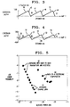
- FIG. 5 is a plot of experimental data comparing bit error rates of received signal for the strategies of FIGs. 3 and 4.
- FIG. 6 is an eye diagram for a signal produced in conventional compensation systems.
- FIG. 7 is an eye diagram for received signal for a system using dispersion averaging.
- this value establishes a maximum dispersion which - is not exceeded but is nominally attained by - intermediate fiber spans, so that, since applied to the dispersionless launched signal, this initial span nominally introduces a degree of dispersion half of that introduced by intermediate spans.
- the inventive teaching will be usefully applied to upgrading of installed systems.
- Plans for upgrading terrestrial systems typically consider 80km compensated spans.
- a common fiber has a positive dispersion of 17ps/nm-km, so that compensation is accomplished by 20km of DCF of negative dispersion of 68ps/nm-km. It is convenient to discuss the invention in terms of such an 80-20 system.
- the threshold between linear and non-linear operation is dependent on launch power density. This in turn depends on fiber characteristics together with customer specifications for span lengths and bit rate. Silica-based fiber characteristically shows a loss in the range of 0.2-1.0dB/km. Less than order-of-magnitude change will have little effect on the conclusions reached in the following discussion, all of which are based on state-of-the-art silica fiber.
- the characteristic curve for non-linear penalty shows a pronounced upturn at a "threshold" value of power.
- This threshold value is inversely proportional to effective core area. Both experimental and simulated information presented are based on 20Gb/sec transmission. Core areas were 20 ⁇ m 2 for the DCF and 80 ⁇ m 2 for the transmission fiber. The threshold value for this DCF is about 0dBm (1mW). The corresponding value for the 4x increased core of the transmission fiber is 4mW.
- a normalized threshold value, required for "non-linear" operation is 0.05mw/ ⁇ m 2 :
- the threshold power requirement is generally met for contemplated systems in which length of positive dispersion transmission fiber in between amplifiers is 30km-40km for per-channel bit rate of 20Gbit, or 60km-80km for 10Gbit operation.
- This power level is inherently attained for compensating fiber, whether DCF or concatenating, for contemplated bit rates. (Bit rates above the presently-used 2.5Gbit/sec., in requiring greater power, increase the severity of the requirement.)
- Systems in planning provide for amplified lengths of up to about 120km. Until fiber loss is substantially reduced so that greater amplified lengths become feasible, DCF-compensated systems will benefit from the inventive teaching only so long as the transmission fiber to be compensated is of positive sign of dispersion.
- the length of negative DCF required for compensation is of sufficiently-reduced core size to result in non-linear operation. (DCF of positive dispersion, of contemplated coil lengths, will likely not operate non-linearly.)
- the operating requirement, for purposes of the invention, is satisfied for any system including two successive amplified fiber spans in non-linear operation.
- likely DCF-compensated systems as well as concatenated systems will include a span of positive dispersion fiber of at least about 30km-40km for 20Gbit operation or equivalent for other bit rates.
- the complete system will now include an initial span of fiber for introducing dispersion of the maximum amplitude specified, and also a terminal span for returning to zero dispersion.
- State-of-the-art transmitters and receivers permit systems including a larger number of intermediate spans.
- a hypothetical system both meeting the operating requirement for maximum dispersion and providing for maximum span length, is made up of intermediate spans of uniform dispersion together with terminal "half-spans" of half that dispersion. These terminal spans account for dispersionless launched and received signals. Terrain and distribution requirements will likely result in some non-uniformity. Imprecision and drifting characteristics may lead to an average total residual dispersion of small finite value. Advantages of averaging over equalization are considered realized so long as this value is no greater than 1/4 of the nominal excursion.
- FIG. 1 shows a generalized single-channel dispersion-averaged compensated system. It includes laser 1, modulator 2, amplifier 3, initial fiber span 4 and amplifier 5.
- DCF is in coil form.
- span 4 together with amplifiers 3 and 5 will be included within transmitter 6 shown in phantom.
- span 4 now a half-span of transmission fiber will be bounded by transmitter-contained amplifier 3 and external amplifier 5.
- Detector 11 is intended to represent an optical-to-electrical converter together with any required ancillary equipment. Five intermediate fiber spans 12, 13, 14, 15 and 16 together with amplifiers 17, 18, 19 and 20 complete the transmission line.
- fiber spans 12, 14 and 16 are of positive dispersion transmission fiber, and spans 13 and 15 are of DCF - likely in compact spools.
- a DCF-compensation system could make use of transmission fiber in terminal half-spans 4 and 8.
- the grouping of amplifier 17-span 13-amplifier 18 will share one housing, and amplifier 19-span 15-amplifier 20 will use another.
- all fiber spans, 4, 12-16, and 8, are transmission fiber spans, and terminal spans 4 and 8 may be of either sign of dispersion.
- FIG. 2 shows the analogous WDM system which now includes WDM 21 and demultiplexer 22.
- Half-spans 30 and 31 together with associated amplifiers, for DCF-compensation, are housed in transmitter 32 and receiver 33.
- FIGs. 3 and 4 are management maps for dispersion compensation.
- FIG. 3 shows the traditional back-to-zero plan:
- FIG. 4 using the same total lengths, shows the averaging plan of the invention.
- the figures may be considered as the DCF-compensation systems of the Examples - using transmission fiber of +17ps/nm-km dispersion and DCF of -80ps/nm-km.
- FIG. 3 on coordinates of dispersion in ps/nm and distance in km, shows six full fiber spans: transmission spans 40, 41 and 42; and DCF spans 43, 44, 45. In this traditional back to zero map, dispersion does not change sign and shows an excursion of +1300ps/nm.
- FIG. 4 maps the modified plan of the invention.
- Half of the full-length terminal span 45 of FIG. 3 has been removed and forms initial half-span 52, and final half-span 55.
- Remaining fiber spans 50-54 are unchanged and of the dispersions of spans 40-45 of FIG. 3. Peak excursions are now ⁇ 650ps/nm.
- FIG. 5 is a plot of bit error rate, for varying levels of received power, comparing the two strategies - curve 60 for back-to-zero and curve 61 for averaging. Data points are experimental for the 232km system descried in the Examples. In addition, data points are presented for back-to-back transmitter and receiver on curve 62. Within measurement error, no dispersion penalty was paid by insertion of the dispersion-averaged transmission line. Curve 60 bottoms at about -23dBm received power, showing that further amplification does not improve error rate.
- FIGs. 6 and 7 are conventional eye diagrams plotted on coordinates of power in milliwatts and time in nanoseconds.
- FIG. 6 representing the prior art approach using the back-to-zero plan of FIG. 3 shows well in excess of the 40% eye closure, considered unacceptable.
- FIG. 7, for dispersion-averaging is taken from Example 1, and is reasonably representative.
- Example 2 using the conventional dispersion management strategy of the FIG. 3 map, produced the unacceptable bit error rates of curve 60 of FIG. 5.
- Example 1 The experimental arrangement was similar to that of FIG. 2, but with additional apparatus for varying launch power and for measurement.
- a single modulator was used to modulate all eight channels, at a rate of 20Gb/s.
- Channel-to-channel spacing was 1.6nm (200Ghz).
- Multiplexed channels were modulated, were amplified to from 0 to 2 dBm/channel, were passed through the initial DCF span, and were amplified to 8dBm/channel at the transmitter output.
- the transmission line included four EDFAs providing for a power level of 2-5dBm/channel at the input to each DCF length and for 5-7dBm/channel at the input to each span of transmission fiber.
- a variable optical attenuator was included in the receiver to develop the varying received powers plotted on FIG. 5.
- Two multilayer interference filters in series provided a tunable bandpass of approximately 0.8nm.
- FIG. 7 shows the corresponding eye diagram derived by computer simulation.
- Example 2 The experimental arrangement differed from that of Example 1 in using six full length fiber spans. The two terminal half-spans of Example 1 are combined to produce the sixth full span at the input to the receiver. The same experimental conditions resulted in the data of curve 60 of FIG. 5 and the eye diagram of FIG. 6.
- FIGs. 1 and 2 do not include a number of elements required in real operation.
- WDM channel separation generally depends on laser stabilization and on optical filtering.
- Dispersion averaging requires three or more spans, so that the two non-linear spans must be combined with at least one additional span. Beyond this number spans need not be non-linear.
- a complete system may include further spans which are not dispersion-averaged - which are dispersion-equalized, or even dispersion-shifted.
- Initial operation of dispersion-averaged systems may not meet requirements for non-linear operation.
- the inventive concept may be applied to systems which operate non-linearly as upgraded, e.g. due to increased bit-rate.
- Dispersion-averaging will be useful for WDM. Both numbered examples pertain to WDM operation.
- the DCF in those instances was of the type described in Optics Letters, vol. 18, no. 11, pp. 924-926 (1993). Its negative slope provided for more nearly constant compensation across the entire WDM set of subchannels. While it was not needed for the system and operations conditions of Example 1, it would be beneficial for longer systems, larger WDM bandwidth, and/or higher bit-rates.
- Initial use is expected to be in upgrading of fiber of substantial dispersion, e.g. the 17ps/nm-km of the Examples.
- Installed spans are of ten or more kilometers, so that residual dispersion is 170ps/nm or more. In accordance with the invention, this excursion is halved so that residual dispersion in the compensated line ranges from +85ps/nm to -85ps/nm. Compensation is contemplated in new systems in which fiber spans have substantially smaller values of residual dispersion.
- One such example uses the fiber of U.S. Pat. 5,327,516, e.g. with dispersion of from 1.5ps/nm-km to 4.0ps/nm-km. Dispersion averaging in such a system may entail residual dispersion maxima as small as ⁇ 50.
Landscapes
- Physics & Mathematics (AREA)
- Electromagnetism (AREA)
- Engineering & Computer Science (AREA)
- Computer Networks & Wireless Communication (AREA)
- Signal Processing (AREA)
- Optical Communication System (AREA)
- Optical Fibers, Optical Fiber Cores, And Optical Fiber Bundles (AREA)
Applications Claiming Priority (2)
| Application Number | Priority Date | Filing Date | Title |
|---|---|---|---|
| US396841 | 1989-08-21 | ||
| US08/396,841 US5559920A (en) | 1995-03-01 | 1995-03-01 | Dispersion compensation in optical fiber communications |
Publications (3)
| Publication Number | Publication Date |
|---|---|
| EP0730354A2 true EP0730354A2 (fr) | 1996-09-04 |
| EP0730354A3 EP0730354A3 (fr) | 1999-04-14 |
| EP0730354B1 EP0730354B1 (fr) | 2001-08-01 |
Family
ID=23568846
Family Applications (1)
| Application Number | Title | Priority Date | Filing Date |
|---|---|---|---|
| EP96301144A Expired - Lifetime EP0730354B1 (fr) | 1995-03-01 | 1996-02-21 | Compensation de dispersion pour systèmes de communication optique |
Country Status (6)
| Country | Link |
|---|---|
| US (1) | US5559920A (fr) |
| EP (1) | EP0730354B1 (fr) |
| JP (1) | JP3522438B2 (fr) |
| KR (1) | KR100437750B1 (fr) |
| CA (1) | CA2170430C (fr) |
| DE (1) | DE69614162T2 (fr) |
Cited By (10)
| Publication number | Priority date | Publication date | Assignee | Title |
|---|---|---|---|---|
| EP0849899A1 (fr) * | 1996-12-19 | 1998-06-24 | Alcatel | Système de transmission à fibre optique en régime de dispersion normal |
| DE19732568C1 (de) * | 1997-07-29 | 1998-09-03 | Lucent Tech Network Sys Gmbh | Verfahren und optisches Übertragungssystem zur Kompensation von Dispersion in optischen Übertragungsstrecken |
| GB2330026A (en) * | 1997-09-25 | 1999-04-07 | Nec Corp | WDM optical signal dispersion compensation |
| WO1999057822A1 (fr) * | 1998-05-01 | 1999-11-11 | Corning Incorporated | Guide d'ondes optiques gere par dispersion et systeme avec amplification distribuee |
| EP0903877A3 (fr) * | 1997-09-12 | 1999-12-15 | Lucent Technologies Inc. | Compensation de dispersion d'une fibre optique |
| WO2001013146A3 (fr) * | 1999-08-13 | 2001-09-13 | Lg Cable Ltd | Cable a fibres optiques presentant une capacite de transmission accrue et systeme de transmission optique a multiplexage en longueur d'onde |
| WO2002003576A3 (fr) * | 2000-06-30 | 2002-08-01 | Nortel Networks Ltd | Procedes, systemes, supports et signaux destines a la determination de precompensation optimale et optimisation d'un systeme optique |
| FR2822311A1 (fr) * | 2001-03-16 | 2002-09-20 | Fujitsu Ltd | Systeme de transmission optique |
| US6943935B2 (en) | 2001-03-16 | 2005-09-13 | Corning Incorporated | Dispersion-managed cable for raman-assisted transmission |
| EP2255232A1 (fr) * | 2008-02-22 | 2010-12-01 | Corning Incorporated | Procédé de sélection d une fibre optique à utiliser dans des systèmes de fibres et de câbles |
Families Citing this family (68)
| Publication number | Priority date | Publication date | Assignee | Title |
|---|---|---|---|---|
| JP3409935B2 (ja) * | 1995-01-13 | 2003-05-26 | 富士通株式会社 | シングルモード光ファイバ及びその製造方法並びに光ファイバ伝送路 |
| JPH08256106A (ja) * | 1995-03-17 | 1996-10-01 | Fujitsu Ltd | 光増幅海底伝送システムの分散補償装置 |
| JP3606628B2 (ja) * | 1995-03-31 | 2005-01-05 | 富士通株式会社 | Smf伝送路を用いた光伝送システム |
| AU693329B2 (en) * | 1995-04-13 | 1998-06-25 | Corning Incorporated | Dispersion managed optical waveguide |
| US5677780A (en) * | 1995-09-06 | 1997-10-14 | Lucent Technologies Inc. | Method of improving the electrical eye margin of an optical fiber transmission system having single mode and dispersion compensating fiber segments |
| CA2201061A1 (fr) * | 1996-03-28 | 1997-09-28 | The Furukawa Electric Co., Ltd. | Fibre optique a dispersion decalee et systeme de transmission a multiplexage en longueur d'onde associe |
| US6014479A (en) * | 1996-10-10 | 2000-01-11 | Tyco Submarine Systems Ltd. | High channel density wavelength division multiplex (WDM) optical transmission system and method with negligible four-wave mixing (FWM) penalty |
| US6201914B1 (en) | 1997-04-15 | 2001-03-13 | UNIVERSITé LAVAL | Tapered waveguide for optical dispersion compensation |
| US6462849B1 (en) * | 1998-09-10 | 2002-10-08 | Northwestern University | Optimizing launch points for dispersion-managed solitons |
| WO1999013588A2 (fr) * | 1997-09-10 | 1999-03-18 | Northwestern University | Optimisation des points de lancement pour solitons a propagation en dispersion conduite |
| JP3337954B2 (ja) * | 1997-09-17 | 2002-10-28 | 株式会社フジクラ | 分散補償光ファイバ |
| JPH1197779A (ja) * | 1997-09-22 | 1999-04-09 | Sony Corp | 多色光の変調増幅器及びこれを用いた投射型表示装置 |
| US6005997A (en) * | 1997-12-31 | 1999-12-21 | Mci Communications Corporation | Long-haul terrestrial optical fiber link having low-power optical line amplifiers with integrated dispersion compensation modules |
| US6356384B1 (en) * | 1998-03-24 | 2002-03-12 | Xtera Communications Inc. | Broadband amplifier and communication system |
| US6600592B2 (en) | 1998-03-24 | 2003-07-29 | Xtera Communications, Inc. | S+ band nonlinear polarization amplifiers |
| US6597493B2 (en) | 2000-05-05 | 2003-07-22 | The Regents Of The University Of Michigan | Nonlinear fiber amplifiers used for a 1430-1530nm low-loss window in optical fibers |
| US6693737B2 (en) | 1998-03-24 | 2004-02-17 | Xtera Communications, Inc. | Dispersion compensating nonlinear polarization amplifiers |
| US6760148B2 (en) | 1998-03-24 | 2004-07-06 | Xtera Communications, Inc. | Nonlinear polarization amplifiers in nonzero dispersion shifted fiber |
| JP3582356B2 (ja) | 1998-05-08 | 2004-10-27 | 富士通株式会社 | 分散補償システム及び分散補償方法 |
| US6335820B1 (en) | 1999-12-23 | 2002-01-01 | Xtera Communications, Inc. | Multi-stage optical amplifier and broadband communication system |
| US6885498B2 (en) | 1998-06-16 | 2005-04-26 | Xtera Communications, Inc. | Multi-stage optical amplifier and broadband communication system |
| DE69942932D1 (de) | 1998-06-16 | 2010-12-23 | Xtera Comm Inc | Dispersionskompensierendes und verstärkendes optisches element |
| US6359725B1 (en) | 1998-06-16 | 2002-03-19 | Xtera Communications, Inc. | Multi-stage optical amplifier and broadband communication system |
| JP3769129B2 (ja) * | 1998-09-03 | 2006-04-19 | 富士通株式会社 | 波長分散補償機能を備えた光増幅器及び光通信システム |
| US6311002B1 (en) * | 1998-12-01 | 2001-10-30 | Tycom (Us) Inc. | Method and apparatus for reducing nonlinear penalties by proper arrangement of the dispersion map in an optical communication system |
| TW455707B (en) * | 1998-12-03 | 2001-09-21 | Sumitomo Electric Industries | Dispersion-equalizing optical fiber and optical transmission line including the same |
| KR100310834B1 (ko) | 1998-12-03 | 2001-12-17 | 오길록 | 고속광전송시스템에서의자동색분산등화장치 |
| AU778609B2 (en) * | 1998-12-03 | 2004-12-16 | Sumitomo Electric Industries, Ltd. | Dispersion equalization optical fiber and optical transmission line including the same |
| US6650842B1 (en) * | 1998-12-18 | 2003-11-18 | Worldcom, Inc. | Optical link with reduced four-wave mixing |
| EP1149479B1 (fr) * | 1998-12-18 | 2006-03-15 | Prysmian Cavi e Sistemi Energia S.r.l. | Systeme et procede optique a faibles pertes et a faibles effets non lineaires |
| JP2000236297A (ja) * | 1999-02-16 | 2000-08-29 | Fujitsu Ltd | 分散補償が適用される光伝送のための方法及びシステム |
| US6360045B1 (en) * | 1999-02-23 | 2002-03-19 | Lasercomm Inc. | High order spatial mode transmission system |
| US6509993B1 (en) | 1999-09-20 | 2003-01-21 | At&T Corp. | Optical transmission using dispersion-enhanced signals |
| US6532330B1 (en) * | 1999-11-04 | 2003-03-11 | Lucent Technologies Inc. | Dispersion managed optical transmission line and method for making same |
| US6792209B1 (en) * | 1999-12-22 | 2004-09-14 | At&T Corp. | Method and system for reducing non-linear cross talk in low dispersion optical fiber |
| US7027698B2 (en) * | 2000-03-03 | 2006-04-11 | Pirelli Cavi E Sistemi S.P.A. | Optical fiber for WDM transmission |
| GB0005615D0 (en) * | 2000-03-09 | 2000-05-03 | Univ Southampton | An optical processing device based on fiber grating |
| US6968132B1 (en) * | 2000-05-16 | 2005-11-22 | Mahi Networks, Inc. | Multiplexing and de-multiplexing optical signals |
| WO2002021173A2 (fr) | 2000-09-06 | 2002-03-14 | Corning Incorporated | Diagramme de dispersion pour fibres optiques a compensation de pente |
| US6571032B1 (en) * | 2000-11-06 | 2003-05-27 | Tyco Telecommunications (Us) Inc. | Apparatus and method for multiplexing and/or demultiplexing optical signals having substantially equal dispersion |
| US6584262B1 (en) * | 2000-11-06 | 2003-06-24 | Tyco Telecommunications (Us) Inc. | Method and apparatus for the optimization of dispersion map using slope-compensating optical fibers |
| US6724964B2 (en) * | 2001-01-30 | 2004-04-20 | Lasercomm Inc. | Optical waveguide exhibiting strongly positive dispersion, and system utilizing same |
| US6810214B2 (en) | 2001-03-16 | 2004-10-26 | Xtera Communications, Inc. | Method and system for reducing degradation of optical signal to noise ratio |
| US6532101B2 (en) | 2001-03-16 | 2003-03-11 | Xtera Communications, Inc. | System and method for wide band Raman amplification |
| US6694081B2 (en) | 2001-04-12 | 2004-02-17 | Corning Incorporated | Dispersion managed cable for WDM systems |
| US20020181879A1 (en) * | 2001-05-31 | 2002-12-05 | Bickham Scott Robertson | Chromatic dispersion compensation and dispersion slope compensation method and apparatus |
| US6587259B2 (en) | 2001-07-27 | 2003-07-01 | Xtera Communications, Inc. | System and method for controlling noise figure |
| US20030026533A1 (en) * | 2001-08-03 | 2003-02-06 | Yochay Danziger | Configurable dispersion management device |
| WO2003052660A1 (fr) | 2001-12-17 | 2003-06-26 | Corning Incorporated | Systeme de selection de bobines de fibres optiques provenant d'un inventaire pour l'execution d'une commande |
| US7251417B2 (en) | 2002-03-08 | 2007-07-31 | Lucent Technologies Inc. | Method and apparatus for optimization of dispersion-managed return-to-zero transmission by employing optical pulses having variable widths |
| US7197245B1 (en) | 2002-03-15 | 2007-03-27 | Xtera Communications, Inc. | System and method for managing system margin |
| US7058311B1 (en) | 2002-03-15 | 2006-06-06 | Xtera Communications, Inc. | System and method for dispersion compensation in an optical communication system |
| US7085039B2 (en) * | 2002-03-15 | 2006-08-01 | Tyco Telecommunications (Us) Inc. | Hybrid Raman/erbium-doped fiber amplifier and transmission system with dispersion map |
| US6819478B1 (en) | 2002-03-15 | 2004-11-16 | Xtera Communications, Inc. | Fiber optic transmission system with low cost transmitter compensation |
| US6778321B1 (en) | 2002-03-15 | 2004-08-17 | Xtera Communications, Inc. | Fiber optic transmission system for a metropolitan area network |
| DE60200139T2 (de) * | 2002-06-11 | 2004-09-30 | Agilent Technologies, Inc. (n.d.Ges.d.Staates Delaware), Palo Alto | Vorrichtung mit reduziertem Verlust durch Rückreflexion |
| US20040028319A1 (en) * | 2002-07-03 | 2004-02-12 | Mahesh Ajgaonkar | Optical communication system and method |
| US6829406B2 (en) | 2002-07-10 | 2004-12-07 | Tropic Networks Inc. | Method and system for determining location and value of dispersion compensating modules in an optical network |
| CA2429475C (fr) * | 2002-08-12 | 2009-01-06 | Tropic Networks Inc. | Methode de determination d'emplacement optimal et de valeur de modules de compensation de dispersion dans un reseau optique |
| US20040037568A1 (en) * | 2002-08-20 | 2004-02-26 | Evangelides Stephen G. | Optical repeater employed in an optical communication system having a modular dispersion map |
| US20040096223A1 (en) * | 2002-08-20 | 2004-05-20 | Red Sky Systems, Inc. | Modular dispersion map for an optical communication system |
| JP4576094B2 (ja) * | 2003-03-03 | 2010-11-04 | 富士通株式会社 | 波長多重光中継伝送方法および中継装置 |
| US7254342B2 (en) * | 2003-10-29 | 2007-08-07 | Fujitsu Limited | Method and system for transmitting information in an optical communication system with low signal distortion |
| US7426323B2 (en) * | 2006-02-08 | 2008-09-16 | Tyco Telecommunications (Us) Inc. | Dispersion management in branched optical networks |
| US7693425B2 (en) * | 2007-01-11 | 2010-04-06 | Fujitsu Limited | Method and system for compensating for optical dispersion in an optical signal in a hybrid optical network |
| US8484462B2 (en) * | 2008-11-07 | 2013-07-09 | Lockheed Martin Corporation | System and method for establishing a self-realizing expandable communications network |
| US9778418B2 (en) | 2012-09-15 | 2017-10-03 | Alcatel Lucent | Multi-mode optical transmission line with differential modal group delay compensation |
| CN106130644B (zh) * | 2016-07-20 | 2018-04-03 | 上海交通大学 | 基于色散过补偿的频域均衡方法 |
Family Cites Families (7)
| Publication number | Priority date | Publication date | Assignee | Title |
|---|---|---|---|---|
| US5035481A (en) * | 1990-08-23 | 1991-07-30 | At&T Bell Laboratories | Long distance soliton lightwave communication system |
| US5218662A (en) * | 1992-05-06 | 1993-06-08 | Alcatel Network Systems, Inc. | Fiber-optic cable system and method for dispersion compensation at nodes between end points |
| US5224183A (en) * | 1992-07-23 | 1993-06-29 | Alcatel Network Systems, Inc. | Multiple wavelength division multiplexing signal compensation system and method using same |
| JP2760233B2 (ja) * | 1992-09-29 | 1998-05-28 | 住友電気工業株式会社 | 光通信装置 |
| US5280383A (en) * | 1992-12-02 | 1994-01-18 | At&T Bell Laboratories | Dual-stage low power optical amplifier |
| US5327516A (en) * | 1993-05-28 | 1994-07-05 | At&T Bell Laboratories | Optical fiber for wavelength division multiplexing |
| US5400165A (en) * | 1993-09-10 | 1995-03-21 | At&T Corp. | Optical communication using dispersion-induced FM to AM conversion with nonlinearity-induced stabilization |
-
1995
- 1995-03-01 US US08/396,841 patent/US5559920A/en not_active Expired - Lifetime
-
1996
- 1996-02-21 EP EP96301144A patent/EP0730354B1/fr not_active Expired - Lifetime
- 1996-02-21 DE DE69614162T patent/DE69614162T2/de not_active Expired - Lifetime
- 1996-02-27 CA CA002170430A patent/CA2170430C/fr not_active Expired - Fee Related
- 1996-02-29 KR KR1019960005380A patent/KR100437750B1/ko not_active Expired - Fee Related
- 1996-03-01 JP JP04448296A patent/JP3522438B2/ja not_active Expired - Fee Related
Cited By (16)
| Publication number | Priority date | Publication date | Assignee | Title |
|---|---|---|---|---|
| US6317241B1 (en) | 1996-12-19 | 2001-11-13 | Alcatel | Normal dispersion fiber optic transmission system |
| FR2757721A1 (fr) * | 1996-12-19 | 1998-06-26 | Alsthom Cge Alcatel | Systeme de transmission a fibre optique en regime de dispersion normal |
| EP0849899A1 (fr) * | 1996-12-19 | 1998-06-24 | Alcatel | Système de transmission à fibre optique en régime de dispersion normal |
| DE19732568C1 (de) * | 1997-07-29 | 1998-09-03 | Lucent Tech Network Sys Gmbh | Verfahren und optisches Übertragungssystem zur Kompensation von Dispersion in optischen Übertragungsstrecken |
| EP0895369A3 (fr) * | 1997-07-29 | 2004-03-31 | Lucent Technologies Network Systems GmbH | Méthode et système de transmission optique pour compensation de la dispersion de lignes de transmission optiques |
| EP0903877A3 (fr) * | 1997-09-12 | 1999-12-15 | Lucent Technologies Inc. | Compensation de dispersion d'une fibre optique |
| GB2330026A (en) * | 1997-09-25 | 1999-04-07 | Nec Corp | WDM optical signal dispersion compensation |
| US6404964B1 (en) | 1998-05-01 | 2002-06-11 | Corning Incorporated | Dispersion managed optical waveguide and system with distributed amplification |
| WO1999057822A1 (fr) * | 1998-05-01 | 1999-11-11 | Corning Incorporated | Guide d'ondes optiques gere par dispersion et systeme avec amplification distribuee |
| WO2001013146A3 (fr) * | 1999-08-13 | 2001-09-13 | Lg Cable Ltd | Cable a fibres optiques presentant une capacite de transmission accrue et systeme de transmission optique a multiplexage en longueur d'onde |
| US6813425B1 (en) | 1999-08-13 | 2004-11-02 | Lg Cable Ltd. And Korea Advanced Institute Of Science And Technology | Fiber optic cable for increased transmission capacity and wavelength division multiplexing optical transmission system using the same |
| WO2002003576A3 (fr) * | 2000-06-30 | 2002-08-01 | Nortel Networks Ltd | Procedes, systemes, supports et signaux destines a la determination de precompensation optimale et optimisation d'un systeme optique |
| FR2822311A1 (fr) * | 2001-03-16 | 2002-09-20 | Fujitsu Ltd | Systeme de transmission optique |
| US6943935B2 (en) | 2001-03-16 | 2005-09-13 | Corning Incorporated | Dispersion-managed cable for raman-assisted transmission |
| US7209654B2 (en) | 2001-03-16 | 2007-04-24 | Fujitsu Limited | Optical transmission system |
| EP2255232A1 (fr) * | 2008-02-22 | 2010-12-01 | Corning Incorporated | Procédé de sélection d une fibre optique à utiliser dans des systèmes de fibres et de câbles |
Also Published As
| Publication number | Publication date |
|---|---|
| JPH08265256A (ja) | 1996-10-11 |
| KR100437750B1 (ko) | 2004-08-06 |
| EP0730354B1 (fr) | 2001-08-01 |
| JP3522438B2 (ja) | 2004-04-26 |
| DE69614162T2 (de) | 2002-03-28 |
| CA2170430C (fr) | 2001-01-16 |
| US5559920A (en) | 1996-09-24 |
| DE69614162D1 (de) | 2001-09-06 |
| EP0730354A3 (fr) | 1999-04-14 |
| CA2170430A1 (fr) | 1996-09-02 |
| KR960036395A (ko) | 1996-10-28 |
Similar Documents
| Publication | Publication Date | Title |
|---|---|---|
| EP0730354B1 (fr) | Compensation de dispersion pour systèmes de communication optique | |
| US5719696A (en) | High capacity optical fiber network | |
| JP2000261377A (ja) | 分散補償光伝送路及びシステム | |
| JPH0946318A (ja) | 波長多重光伝送システム及び該伝送システムに用いる光送信装置 | |
| US6782175B2 (en) | Dispersion map for slope compensating fibers | |
| US6626591B1 (en) | Method of reducing intensity distortion induced by cross phase modulation in a WDM optical fiber transmission system | |
| Tkach et al. | Transmission of eight 20-Gb/s channels over 232 km of conventional single-mode fiber | |
| US6768872B1 (en) | Optical transmission system, optical transmission line and optical transmitter | |
| US6674557B1 (en) | Wavelength division multiplexing systems | |
| EP1241809A1 (fr) | Système de transmission optique comprenant des lignes de transmission optique à compensation de dispersion | |
| EP1142178A2 (fr) | Systemes de multiplexage en longueur d'onde | |
| Eiselt | The impact of non-linear fiber effects on fiber choice for ultimate transmission capacity | |
| US7756423B2 (en) | Wavelength division multiplexing optical transmission apparatus, wavelength division multiplexing optical transmission system and wavelength division multiplexing optical transmission method | |
| Koga et al. | 10 Gb/s, 16 channel unrepeated WDM transmission over 340 km of standard single mode fiber with very high power amplifier | |
| US6577424B1 (en) | Chromatic dispersion compensator providing dispersion compensation to select channels of a wavelength division multiplexed signal | |
| JP2000357992A (ja) | 光伝送路及び光伝送システム | |
| AU728349B2 (en) | High capacity optical fiber network | |
| HK1004728B (en) | High capacity optical fiber network and fiber |
Legal Events
| Date | Code | Title | Description |
|---|---|---|---|
| PUAI | Public reference made under article 153(3) epc to a published international application that has entered the european phase |
Free format text: ORIGINAL CODE: 0009012 |
|
| AK | Designated contracting states |
Kind code of ref document: A2 Designated state(s): DE FR GB IT |
|
| PUAL | Search report despatched |
Free format text: ORIGINAL CODE: 0009013 |
|
| AK | Designated contracting states |
Kind code of ref document: A3 Designated state(s): DE FR GB IT |
|
| 17P | Request for examination filed |
Effective date: 19991001 |
|
| 17Q | First examination report despatched |
Effective date: 19991229 |
|
| GRAG | Despatch of communication of intention to grant |
Free format text: ORIGINAL CODE: EPIDOS AGRA |
|
| GRAG | Despatch of communication of intention to grant |
Free format text: ORIGINAL CODE: EPIDOS AGRA |
|
| GRAH | Despatch of communication of intention to grant a patent |
Free format text: ORIGINAL CODE: EPIDOS IGRA |
|
| GRAH | Despatch of communication of intention to grant a patent |
Free format text: ORIGINAL CODE: EPIDOS IGRA |
|
| GRAA | (expected) grant |
Free format text: ORIGINAL CODE: 0009210 |
|
| AK | Designated contracting states |
Kind code of ref document: B1 Designated state(s): DE FR GB IT |
|
| REF | Corresponds to: |
Ref document number: 69614162 Country of ref document: DE Date of ref document: 20010906 |
|
| ET | Fr: translation filed | ||
| REG | Reference to a national code |
Ref country code: GB Ref legal event code: IF02 |
|
| PLBE | No opposition filed within time limit |
Free format text: ORIGINAL CODE: 0009261 |
|
| STAA | Information on the status of an ep patent application or granted ep patent |
Free format text: STATUS: NO OPPOSITION FILED WITHIN TIME LIMIT |
|
| 26N | No opposition filed | ||
| REG | Reference to a national code |
Ref country code: FR Ref legal event code: TP Owner name: ALCATEL-LUCENT USA INC., US Effective date: 20130823 Ref country code: FR Ref legal event code: CD Owner name: ALCATEL-LUCENT USA INC., US Effective date: 20130823 |
|
| REG | Reference to a national code |
Ref country code: GB Ref legal event code: 732E Free format text: REGISTERED BETWEEN 20140102 AND 20140108 |
|
| REG | Reference to a national code |
Ref country code: GB Ref legal event code: 732E Free format text: REGISTERED BETWEEN 20140109 AND 20140115 |
|
| PGFP | Annual fee paid to national office [announced via postgrant information from national office to epo] |
Ref country code: DE Payment date: 20140219 Year of fee payment: 19 |
|
| REG | Reference to a national code |
Ref country code: FR Ref legal event code: GC Effective date: 20140410 |
|
| PGFP | Annual fee paid to national office [announced via postgrant information from national office to epo] |
Ref country code: IT Payment date: 20140227 Year of fee payment: 19 Ref country code: FR Payment date: 20140219 Year of fee payment: 19 |
|
| PGFP | Annual fee paid to national office [announced via postgrant information from national office to epo] |
Ref country code: GB Payment date: 20140218 Year of fee payment: 19 |
|
| REG | Reference to a national code |
Ref country code: FR Ref legal event code: RG Effective date: 20141015 |
|
| REG | Reference to a national code |
Ref country code: DE Ref legal event code: R119 Ref document number: 69614162 Country of ref document: DE |
|
| GBPC | Gb: european patent ceased through non-payment of renewal fee |
Effective date: 20150221 |
|
| REG | Reference to a national code |
Ref country code: FR Ref legal event code: ST Effective date: 20151030 |
|
| PG25 | Lapsed in a contracting state [announced via postgrant information from national office to epo] |
Ref country code: IT Free format text: LAPSE BECAUSE OF NON-PAYMENT OF DUE FEES Effective date: 20150221 |
|
| PG25 | Lapsed in a contracting state [announced via postgrant information from national office to epo] |
Ref country code: DE Free format text: LAPSE BECAUSE OF NON-PAYMENT OF DUE FEES Effective date: 20150901 Ref country code: GB Free format text: LAPSE BECAUSE OF NON-PAYMENT OF DUE FEES Effective date: 20150221 |
|
| PG25 | Lapsed in a contracting state [announced via postgrant information from national office to epo] |
Ref country code: FR Free format text: LAPSE BECAUSE OF NON-PAYMENT OF DUE FEES Effective date: 20150302 |