EP0731236B1 - Dispositif de fixation sous dalle pour barreau-support de garde-corps - Google Patents
Dispositif de fixation sous dalle pour barreau-support de garde-corps Download PDFInfo
- Publication number
- EP0731236B1 EP0731236B1 EP96420058A EP96420058A EP0731236B1 EP 0731236 B1 EP0731236 B1 EP 0731236B1 EP 96420058 A EP96420058 A EP 96420058A EP 96420058 A EP96420058 A EP 96420058A EP 0731236 B1 EP0731236 B1 EP 0731236B1
- Authority
- EP
- European Patent Office
- Prior art keywords
- slab
- fixing
- under
- shoe
- screw
- Prior art date
- Legal status (The legal status is an assumption and is not a legal conclusion. Google has not performed a legal analysis and makes no representation as to the accuracy of the status listed.)
- Expired - Lifetime
Links
- 230000000295 complement effect Effects 0.000 claims abstract description 5
- 239000007787 solid Substances 0.000 claims 2
- 238000009434 installation Methods 0.000 description 5
- 210000000003 hoof Anatomy 0.000 description 3
- 230000000903 blocking effect Effects 0.000 description 2
- 230000007547 defect Effects 0.000 description 2
- 238000009418 renovation Methods 0.000 description 2
- 229910000838 Al alloy Inorganic materials 0.000 description 1
- 240000008042 Zea mays Species 0.000 description 1
- 210000003423 ankle Anatomy 0.000 description 1
- 230000005540 biological transmission Effects 0.000 description 1
- 230000006835 compression Effects 0.000 description 1
- 238000007906 compression Methods 0.000 description 1
- 238000010276 construction Methods 0.000 description 1
- 238000001514 detection method Methods 0.000 description 1
- 238000000034 method Methods 0.000 description 1
- 230000004048 modification Effects 0.000 description 1
- 238000012986 modification Methods 0.000 description 1
- 238000005457 optimization Methods 0.000 description 1
- 238000005192 partition Methods 0.000 description 1
Images


Classifications
-
- E—FIXED CONSTRUCTIONS
- E04—BUILDING
- E04F—FINISHING WORK ON BUILDINGS, e.g. STAIRS, FLOORS
- E04F11/00—Stairways, ramps, or like structures; Balustrades; Handrails
- E04F11/18—Balustrades; Handrails
- E04F11/181—Balustrades
- E04F11/1812—Details of anchoring to the wall or floor
-
- E—FIXED CONSTRUCTIONS
- E04—BUILDING
- E04B—GENERAL BUILDING CONSTRUCTIONS; WALLS, e.g. PARTITIONS; ROOFS; FLOORS; CEILINGS; INSULATION OR OTHER PROTECTION OF BUILDINGS
- E04B1/00—Constructions in general; Structures which are not restricted either to walls, e.g. partitions, or floors or ceilings or roofs
- E04B1/003—Balconies; Decks
Definitions
- the present invention relates to a device for fixing under slab, for railing support bar, including balcony railings.
- Balcony railings generally include support bars, which support a handrail as well as a filling or bar, the base of each support bar being fixed to the balcony slab.
- the base of each support bar is placed and fixed on the upper surface of the balcony, a short distance from the front edge of the slab, says "slab nose”.
- This traditional method of fixation has certain disadvantages, in particular: means of fixing the support bars are very exposed weather, their presence on the upper surface slab can represent an annoying obstacle, and they weaken the area of the slab nose.
- German patent application DE-A-4324602. This device uses a particular horizontal piece which is applied, and fixed by screws, under the underside of the balcony slab. At the front of this room is provided a vertical element on which fits, without possibility the base of the railing support bar. The angular adjustment is achieved by means of a small shim mobile arranged on the horizontal part. This piece is therefore not applied, by a continuous surface important, against the underside of the slab. So, the adjustment device of document DE-A-4324602 does not not allow to distribute on a continuous surface appreciable compression load on concrete, which results in railing instability when the support bar is stressed. We will also note that, in this document, the positioning of the adjustment shim appears difficult.
- the present invention aims to eliminate all of these disadvantages, by providing a fixing device under improved slab, which while retaining a simple and economical structure allows adjustments in all directions, conveniently with access from the top of the slab, and also allows a optimization of the mechanical link and transmission efforts, between the components of the device fixing under slab and the slab itself.
- the invention provides a device for fixing under slab, which requires a minimum number of components, while allowing adjustment in all directions by the cooperation of two surfaces complementary, spherical or similar, allowing compensate for geometric defects in the slab and always place the support bar according to the orientation desired.
- the fixing under a slab, object of the invention allows place the support bar not only in one position vertical, but also in an inclined position which can be necessary in some cases especially when a gutter must be placed in front of the nose of slab.
- the fixing profile under slab is positioned so that its end before, and therefore the end piece on the surface convex exterior, located in front of the slab nose, which saves the space necessary for the gutter.
- the fixing profile under the slab is positioned so that its front end, and therefore the outer surface end piece convex, located practically to the right of the slab nose.
- this one can be used with existing support bars, in particular the support bars constituted by a simple straight profile, the upper part of the hoof comprising a housing open upwards, receiving the base of the support bar.
- the position provided for the adjustment means allows direct application of the fixing profile under slab against the underside of the slab, without interposition of no wedges, which provides a surface of important contact on which the efforts.
- the fixing profile under the slab has a flat upper face, pressing against the face bottom of the slab. It is for example a profile tubular having a generally semicircular section. This profile may have an internal part relatively massive, scheduled to be drilled vertically at the location of the or each screw fixing to the slab. To allow access to this screw, the fixing profile under the slab may also have, in the lower region of its outer wall, a cut made in correspondence with the location of the fixing screw, this cutout being able to be closed by fitting a cover.
- the means of fixing the shoe against the end piece are constituted by a single fixing screw, passing through said end piece and clamped in a channel longitudinal of the fixing profile under the slab, formed in the relatively massive internal part of this profile.
- the concave base of the hoof has, in its middle, a buttonhole opening for placement shoe on the fixing screw already in place.
- the base of the shoe still advantageously presents, in its part front, an opening allowing access to the screw fixing, the opening in question being able to be closed by fitting a cover. So the screw of shoe attachment is pre-mounted, and the installation of this shoe, followed by its adjustment and its blocking in the set position, easily operated from above the slab. Note also that the setting according to all directions take place at a single point. Once the adjustment and tightening of the shoe made, the installation of the cover ensures the concealment and the protection of the fixing screw, while leaving it accessible after removing this cache.
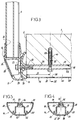
- FIG. 1 shows, in cross section, a balcony slab 1 whose front edge 2 forms the "nose of slab ".
- the balcony slab 1 receives a railing, designated as a whole by the reference 3, which includes rectilinear support bars 4 arranged at intervals, the vertices of which support a handrail 5.
- the railing 3 also includes a filling 6, mounted between an upper beam 7 and a lower beam 8 which are both fixed to the support bars 4 by suitable connecting pieces, respectively 9 and 10.
- the support bars 4, the handrail 5 and the rails 7 and 8 are constituted by aluminum alloy profiles.
- the support bars 4 are fixed vertically, and located just in front of the filling 6, itself placed in the vertical plane passing through the slab nose 2.
- Each support bar 4 is fixed under the slab 1, by means of a fixing under a slab designated as a whole by 11 and described in detail below, the base of this support bar 4 thus being located just in front of the slab nose 2.
- the same device for fixing under slab 11 also applies to a support bar 4 slightly tilted vertically, the base of the support bar 4 being offset forward so as to allow the fixing of a gutter 12 against the nose of slab 2.
- filling 6 of the railing remains in a vertical plane passing through the nose slab 2, the bottom rail 8 of this filling 6 being connected to each support bar 4 by a rod substantially horizontal link 13.
- the device 11 mainly consists of a fixing profile under slab 14, of a terminal piece 15 mounted at the front of the profile 14 and a shoe 16 fixed against the end piece 15 and receiving the base of the support bar 4.
- the fixing profile under slab 14 is a tubular profile, of symmetrical section having a shape general semicircular, its large flat face 17 being applied under the underside 18 of the slab 1.
- This profile 14 has internal longitudinal partitions 19, dividing it internally into two lateral chambers 20 and 21, and an intermediate chamber 22, the latter having a substantially square section - see figures 4 and 5.
- Profile 14 also has an internal part 23 relatively massive, pierced longitudinally with a channel 24 of circular section.
- the profile 14 is fixed under the slab 1 by means a vertical screw 25, located at a distance predetermined D of the slab nose 2.
- a vertical screw 25 located at a distance predetermined D of the slab nose 2.
- the massive part 23 of the profile 14 is pierced perpendicular to channel 24, as indicated in 26 (see Figures 3 and 4), so as to provide a passage vertical for screw 25.
- the lower region of the substantially semi-cylindrical wall 27 of the profile 14 is cut locally, as indicated in 28, forming a "window" through which the intermediate chamber 22 of the profile 14 opens outwards.
- the end piece 15 has a surface outer 29 convex, in particular in a spherical cap. This end piece 15 extends perpendicular to the longitudinal detection of profile 14. It is fixed against the front end of this profile 14.
- Shoe 16 clearly visible in Figures 3 and 6, has a concave base 30, in particular in a crown spherical, complementary to the external surface 29 of the end piece 15.
- the upper part of the shoe 16 forms a housing 31 open upwards, receiving the base of the support bar 4 which is immobilized there by means a blocking device known per se (not represented).
- the concave base 30 of the shoe 16 has, in its middle, a buttonhole opening 32 intended to be crossed by a fixing screw 33, which also crosses the end piece 15 and which is introduced and clamped in channel 24 of profile 14.
- the base 30 of the shoe 16 has an opening rectangular 34, allowing access to the screw head mounting 33.
- the profile 14 is fixed under the slab 1 by means of the screw 25.
- a vertical support bar 4 Figures 1 and 3
- the front end of the fixing profile under slab 14 is positioned practically in line with the nose slab 2.
- an inclined support bar 4 Figure 2
- the front end of the profile 14 is, at opposite, positioned in front of the slab nose 2.
- This front end of profile 14 receives in all cases the end piece 15, which is fixed to it by means of screws (not shown) inserted and tightened in two grooves internal 35 and 36 of profile 14 - see figures 4 and 5.
- Shoe 16 is applied by its concave base 30, against the convex outer surface 29 of the part 15.
- the tightening of the screw 33 fixes the shoe 16 against the end piece 15 in the relative position desired, allowing adjustment according to all directions from space.
- the shoe 16 can thus be positioned and immobilized in a position placing the support bar 4 in a vertical position ( Figures 1 and 3), or in a position placing the support bar 4 in the inclined position ( Figure 2).
- the profile fixing under slab 14 has, between the screw fixing 25 to slab 1 and its rear end closed by the cover 39, a length L which can be relatively large.
- the length L is determined in according to the requirements prescribed by the standards in force in the country concerned, and by the constraints of strength of the fastening device, especially characteristics of the anchor 40, embedded in the slab 1, which receives the fixing screw 25.
- a lengthening of the length L therefore of the distance between the screw 25 and the rear end of profile 14, allows reduce, by leveraging easily understandable, the forces exerted on the screw 25 and / or on the ankle 40, under the action of the weight of the railing 3 and external forces transmitted by this railing.
- This fixing device under slab 11 is applicable to new constructions and works renovation. It not only concerns the slabs of balconies, substantially horizontal, but also the climbs staircase with fixing under an inclined surface, the spherical configuration of the end piece 15 and the shoe 16 allowing, in all cases of application, to fix the support bar 4 in a vertical position or substantially vertical.
- this fixing under slab 11 is applicable, without modification, not only to a filling railing 6 such as described but also to a railing with bars.
- we would not stray from the scope of the invention by providing, in cases where this proves necessary, two profile fixing screws under the slab, instead with a single screw, or by replacing this fixing screw by any equivalent means, such as a threaded rod crossing the slab right through, on all its thickness.
Landscapes
- Engineering & Computer Science (AREA)
- Architecture (AREA)
- Civil Engineering (AREA)
- Structural Engineering (AREA)
- Physics & Mathematics (AREA)
- Electromagnetism (AREA)
- Bridges Or Land Bridges (AREA)
- Steps, Ramps, And Handrails (AREA)
- Refuge Islands, Traffic Blockers, Or Guard Fence (AREA)
- Forms Removed On Construction Sites Or Auxiliary Members Thereof (AREA)
- Reinforcement Elements For Buildings (AREA)
Description
- Comme il ressort de ce qui précède, sa mise en oeuvre nécessite des barreaux-supports de configuration spéciale, notamment à leur base.
- Les dispositifs de fixation à étrier ne permettent pas un réglage multidirectionnel, alors que celui-ci apparaít indispensable pour compenser les défauts géométriques de la dalle.
- La présence d'un double dispositif de fixation à étrier rend l'ensemble assez compliqué et coûteux, et l'un des dispositifs à étrier reste obligatoirement assez proche du nez de dalle.
- Toutes les opérations manuelles de fixation doivent être réalisées par le dessous de la dalle, ce qui est peu commode.
- Les moyens de fixation sous dalle, notamment les étriers et les vis associées, ne sont ni dissimulés, ni protégés.
- un profilé de fixation sous dalle, sensiblement horizontal, dont la partie supérieure est appliquée sous la face inférieure de la dalle et y est fixée au moyen d'au moins une vis ou similaire, l'extrémité avant du profilé étant située sensiblement au niveau du nez de dalle,
- une pièce terminale montée à l'extrémité avant du profilé de fixation sous dalle, la pièce terminale possédant une surface extérieure convexe, notamment sphérique,
- un sabot possédant une embase concave, complémentaire de la surface convexe de la pièce terminale précitée, et une partie supérieure prévue pour l'emboítement et la fixation de la base du barreau-support, et
- des moyens de fixation du sabot, par son embase concave, contre la surface extérieure convexe de ladite pièce terminale, dans une position relative correspondant à la position désirée du barreau-support.
Claims (12)
- Dispositif de fixation sous dalle (1) pour barreausupport (4) de garde-corps, notamment de garde-corps de balcon, ledit dispositif comprenant :un profilé de fixation sous dalle (14), sensiblement horizontal, dont la partie supérieure (17) est destinée à être appliquée sous la face inférieure (18) de la dalle (1) et à y être fixée au moyen d'au moins une vis (25) ou similaire, l'extrémité avant du profilé (14) étant destinée à être située sensiblement au niveau du nez de dalle (2),une pièce terminale (15) montée à l'extrémité avant du profilé de fixation sous dalle (14), la pièce terminale (15) possédant une surface extérieure convexe (29), notamment sphérique,un sabot (16) possédant une embase concave (30), complémentaire de la surface convexe (29) de la pièce terminale (15) précitée, et une partie supérieure (31) prévue pour l'emboítement et la fixation de la base du barreau-support (4), etdes moyens de fixation (32,33) du sabot (16), par son embase concave (30), contre la surface extérieure convexe (29) de ladite pièce terminale (15), dans une position relative correspondant à la position désirée du barreau-support (4).
- Dispositif selon la revendication 1, caractérisé en ce que, dans le cas d'un barreau-support (4) à fixer verticalement, le profilé de fixation sous dalle (14) peut être positionné de telle sorte que son extrémité avant, et par conséquent la pièce terminale (15) à surface convexe (29), se situent pratiquement au droit du nez de dalle (2).
- Dispositif selon la revendication 1, caractérisé en ce que, dans le cas d'un barreau-support (4) à fixer en position inclinée, lorsqu'une gouttière (12) doit être placée devant le nez de dalle (2), le profilé de fixation sous dalle (14) peut être positionné de telle manière que son extrémité avant, et par conséquent la pièce terminale (15) à surface convexe (29), se situent en avant du nez de dalle (2), pour ménager l'espace nécessaire à la gouttière (12).
- Dispositif selon l'une quelconque des revendications 1 à 3, caractérisé en ce que le profilé de fixation sous dalle (14) possède, entre sa vis de fixation (25) à la dalle (1) et son extrémité postérieure (39), une longueur (L) pouvant être relativement importante, adaptée aux exigences de la fixation par vis (25,40).
- Dispositif selon l'une quelconque des revendications 1 à 4, caractérisé en ce que le profilé de fixation sous dalle (14) possède une face supérieure plane (17) destinée à s'appliquer contre la face inférieure (18) de la dalle (1).
- Dispositif selon la revendication 5, caractérisé en ce que le profilé de fixation sous dalle (14) est un profilé tubulaire possédant une section de forme générale semi-circulaire.
- Dispositif selon la revendication 5 ou 6, caractérisé en ce que le profilé de fixation sous dalle (14) comporte une partie interne relativement massive (23), prévue pour être percée verticalement (en 26) à l'emplacement de la ou de chaque vis de fixation (25) à la dalle (1).
- Dispositif selon la revendication 7, caractérisé en ce que le profilé de fixation sous dalle (14) présente, dans la région inférieure de sa paroi extérieure (27), une découpe (28) réalisée en correspondance avec l'emplacement de la vis de fixation (25), cette découpe (28) étant apte à être obturée par mise en place d'un cache (37).
- Dispositif selon la revendication 7 ou 8, caractérisé en ce que les moyens de fixation du sabot (16) contre la pièce terminale (15) sont constitués par une vis de fixation (33) unique, traversant ladite pièce terminale (15) et serrée dans un canal longitudinal (24) du profilé de fixation sous dalle (14), ménagé dans la partie interne relativement massive (23) de ce profilé (14).
- Dispositif selon la revendication 9, caractérisé en ce que l'embase concave (30) du sabot (16) présente, en son milieu, une ouverture en boutonnière (32) pour la mise en place du sabot (16) sur la vis de fixation (33).
- Dispositif selon la revendication 9 ou 10, caractérisé en ce que l'embase (30) du sabot (16) présente, dans sa partie antérieure, une ouverture (34) permettant l'accès à la vis de fixation (33), l'ouverture (34) étant apte à être obturée par la mise en place d'un cache (38).
- Dispositif selon l'une quelconque des revendications 1 à 11, caractérisé en ce que la partie supérieure du sabot (16) comporte un logement (31) ouvert vers le haut, destinée à recevoir la base du barreau-support (4).
Applications Claiming Priority (2)
| Application Number | Priority Date | Filing Date | Title |
|---|---|---|---|
| FR9503160A FR2731454B1 (fr) | 1995-03-10 | 1995-03-10 | Dispositif de fixation sous dalle pour barreau-support de garde-corps |
| FR9503160 | 1995-03-10 |
Publications (2)
| Publication Number | Publication Date |
|---|---|
| EP0731236A1 EP0731236A1 (fr) | 1996-09-11 |
| EP0731236B1 true EP0731236B1 (fr) | 1999-08-04 |
Family
ID=9477161
Family Applications (1)
| Application Number | Title | Priority Date | Filing Date |
|---|---|---|---|
| EP96420058A Expired - Lifetime EP0731236B1 (fr) | 1995-03-10 | 1996-02-22 | Dispositif de fixation sous dalle pour barreau-support de garde-corps |
Country Status (4)
| Country | Link |
|---|---|
| EP (1) | EP0731236B1 (fr) |
| AT (1) | ATE182947T1 (fr) |
| DE (1) | DE69603523T2 (fr) |
| FR (1) | FR2731454B1 (fr) |
Cited By (1)
| Publication number | Priority date | Publication date | Assignee | Title |
|---|---|---|---|---|
| EP3056632A1 (fr) | 2015-02-14 | 2016-08-17 | Klaus Peter Abel | Bordure pour sols de balcon et de terrasse |
Families Citing this family (3)
| Publication number | Priority date | Publication date | Assignee | Title |
|---|---|---|---|---|
| GB9705307D0 (en) * | 1997-03-14 | 1997-04-30 | Ultraframe Plc | Coservatory roofs |
| DE102004014071A1 (de) * | 2004-03-23 | 2005-10-20 | Manfred Richard Dachbau Gmbh | Randausbildung an Balkonen |
| EP3812531B1 (fr) | 2019-10-22 | 2024-05-01 | Hertkorn, Regina | Système de profilé permettant de maintenir un élément de surface |
Family Cites Families (6)
| Publication number | Priority date | Publication date | Assignee | Title |
|---|---|---|---|---|
| DE1936522A1 (de) * | 1968-09-12 | 1970-08-27 | Andersson Sven Lennart | Vorrichtung zum Befestigen eines Gelaenderpfostens |
| FR2316410A1 (fr) * | 1975-06-30 | 1977-01-28 | Lelorieux Michel | Socle reglable |
| DE3702128C2 (de) * | 1987-01-24 | 1996-10-17 | Sks Stakusit Kunststoff Gmbh | Halterung zur ausrichtbaren Befestigung der Pfosten eines Balkongeländers |
| DE4304737A1 (de) * | 1993-02-12 | 1994-08-18 | Mark Tainer Maerkische Stahl U | Befestigungselement für eine Geländerkonstruktion |
| DE4324602A1 (de) * | 1993-07-22 | 1995-01-26 | Werzalit Ag & Co | Pfostenhalter für vorgesetzte Balkongeländer |
| DE9419270U1 (de) * | 1994-01-17 | 1995-01-26 | Gebrüder Kömmerling Kunststoffwerke GmbH, 66954 Pirmasens | Befestigungsvorrichtung für Balkongeländer |
-
1995
- 1995-03-10 FR FR9503160A patent/FR2731454B1/fr not_active Expired - Fee Related
-
1996
- 1996-02-22 EP EP96420058A patent/EP0731236B1/fr not_active Expired - Lifetime
- 1996-02-22 AT AT96420058T patent/ATE182947T1/de not_active IP Right Cessation
- 1996-02-22 DE DE69603523T patent/DE69603523T2/de not_active Expired - Fee Related
Cited By (3)
| Publication number | Priority date | Publication date | Assignee | Title |
|---|---|---|---|---|
| EP3056632A1 (fr) | 2015-02-14 | 2016-08-17 | Klaus Peter Abel | Bordure pour sols de balcon et de terrasse |
| DE102015001891A1 (de) | 2015-02-14 | 2016-08-18 | Klaus Peter Abel | Randeinfassung für Balkon- und Terrassenböden |
| DE102015001891B4 (de) * | 2015-02-14 | 2016-09-15 | Klaus Peter Abel | Randeinfassung für Balkon- und Terrassenböden |
Also Published As
| Publication number | Publication date |
|---|---|
| DE69603523D1 (de) | 1999-09-09 |
| DE69603523T2 (de) | 1999-11-25 |
| FR2731454B1 (fr) | 1997-04-25 |
| FR2731454A1 (fr) | 1996-09-13 |
| ATE182947T1 (de) | 1999-08-15 |
| EP0731236A1 (fr) | 1996-09-11 |
Similar Documents
| Publication | Publication Date | Title |
|---|---|---|
| FR2930270A1 (fr) | Dispositif d'encastrement d'un panneau en un materiau de type verre | |
| EP0586320A1 (fr) | Système pour la fixation d'un raidisseur de mur-rideau sur un élément de construction | |
| EP0170597A1 (fr) | Corniche pour ouvrage d'art | |
| EP0731236B1 (fr) | Dispositif de fixation sous dalle pour barreau-support de garde-corps | |
| EP0651112A1 (fr) | Garde-corps modulaire à lisses horizontales ou inclinées | |
| EP0651110B1 (fr) | Dispositif d'immobilisation d'un raidisseur vertical pour garde-corps vis-a-vis d'un support d'appui au sol | |
| EP1052344B1 (fr) | Kit pour le montage d'un escalier droit et procédé de montage utilisant ce kit | |
| EP0651097B1 (fr) | Assemblage de barreaux avec une lisse de garde-corps | |
| FR2633319A2 (fr) | Glissiere de securite perfectionnee | |
| EP1561864A1 (fr) | Dispositif d'assemblage de deux modules de barrière de sécurité routière préfabriqués en béton | |
| FR2833630A1 (fr) | Glissiere de securite bois | |
| FR2947851A1 (fr) | Dispositif formant garde-corps de securite et potelet de garde-corps de securite | |
| FR2717196A1 (fr) | Dispositif d'assemblage perfectionné de glissières de sécurité routière en bois. | |
| FR2887271A1 (fr) | Dispositif pour la pose de garde-corps | |
| FR2819861A1 (fr) | Dispositif pour fixer en bout une barre sur un support | |
| FR2651811A1 (fr) | Barriere metallique a barreaudage vertical. | |
| FR2960576A1 (fr) | Escalier comprenant au moins un limon | |
| FR2585751A1 (fr) | Coffrage de bord de plafond | |
| EP2492414B1 (fr) | Garde-corps modulaire avec dispositif de réglage | |
| FR2739129A1 (fr) | Montant d'huisserie et huisserie comportant un tel montant, notamment pour bloc-porte | |
| WO2004102501A1 (fr) | Dispositif de protection adapte pour cloturer un ouvrage tel qu’une piscine | |
| EP1640529A1 (fr) | Garde-corps de protection | |
| FR2895003A1 (fr) | Potelet garde-corps de securite | |
| FR2728002A1 (fr) | Structure de garde-corps | |
| FR2637635A1 (fr) | Rambarde perfectionnee et dispositif permettant sa fixation au sol |
Legal Events
| Date | Code | Title | Description |
|---|---|---|---|
| PUAI | Public reference made under article 153(3) epc to a published international application that has entered the european phase |
Free format text: ORIGINAL CODE: 0009012 |
|
| AK | Designated contracting states |
Kind code of ref document: A1 Designated state(s): AT BE CH DE DK ES GB GR IT LI NL SE |
|
| 17P | Request for examination filed |
Effective date: 19961015 |
|
| GRAG | Despatch of communication of intention to grant |
Free format text: ORIGINAL CODE: EPIDOS AGRA |
|
| GRAG | Despatch of communication of intention to grant |
Free format text: ORIGINAL CODE: EPIDOS AGRA |
|
| GRAH | Despatch of communication of intention to grant a patent |
Free format text: ORIGINAL CODE: EPIDOS IGRA |
|
| 17Q | First examination report despatched |
Effective date: 19981222 |
|
| GRAH | Despatch of communication of intention to grant a patent |
Free format text: ORIGINAL CODE: EPIDOS IGRA |
|
| GRAA | (expected) grant |
Free format text: ORIGINAL CODE: 0009210 |
|
| AK | Designated contracting states |
Kind code of ref document: B1 Designated state(s): AT BE CH DE DK ES GB GR IT LI NL SE |
|
| PG25 | Lapsed in a contracting state [announced via postgrant information from national office to epo] |
Ref country code: SE Free format text: THE PATENT HAS BEEN ANNULLED BY A DECISION OF A NATIONAL AUTHORITY Effective date: 19990804 Ref country code: NL Free format text: LAPSE BECAUSE OF FAILURE TO SUBMIT A TRANSLATION OF THE DESCRIPTION OR TO PAY THE FEE WITHIN THE PRESCRIBED TIME-LIMIT Effective date: 19990804 Ref country code: IT Free format text: LAPSE BECAUSE OF FAILURE TO SUBMIT A TRANSLATION OF THE DESCRIPTION OR TO PAY THE FEE WITHIN THE PRESCRIBED TIME-LIMIT;WARNING: LAPSES OF ITALIAN PATENTS WITH EFFECTIVE DATE BEFORE 2007 MAY HAVE OCCURRED AT ANY TIME BEFORE 2007. THE CORRECT EFFECTIVE DATE MAY BE DIFFERENT FROM THE ONE RECORDED. Effective date: 19990804 Ref country code: GR Free format text: LAPSE BECAUSE OF NON-PAYMENT OF DUE FEES Effective date: 19990804 Ref country code: GB Free format text: LAPSE BECAUSE OF FAILURE TO SUBMIT A TRANSLATION OF THE DESCRIPTION OR TO PAY THE FEE WITHIN THE PRESCRIBED TIME-LIMIT Effective date: 19990804 Ref country code: ES Free format text: THE PATENT HAS BEEN ANNULLED BY A DECISION OF A NATIONAL AUTHORITY Effective date: 19990804 Ref country code: AT Free format text: LAPSE BECAUSE OF FAILURE TO SUBMIT A TRANSLATION OF THE DESCRIPTION OR TO PAY THE FEE WITHIN THE PRESCRIBED TIME-LIMIT Effective date: 19990804 |
|
| REF | Corresponds to: |
Ref document number: 182947 Country of ref document: AT Date of ref document: 19990815 Kind code of ref document: T |
|
| REG | Reference to a national code |
Ref country code: CH Ref legal event code: EP |
|
| REF | Corresponds to: |
Ref document number: 69603523 Country of ref document: DE Date of ref document: 19990909 |
|
| PG25 | Lapsed in a contracting state [announced via postgrant information from national office to epo] |
Ref country code: DK Free format text: LAPSE BECAUSE OF FAILURE TO SUBMIT A TRANSLATION OF THE DESCRIPTION OR TO PAY THE FEE WITHIN THE PRESCRIBED TIME-LIMIT Effective date: 19991104 |
|
| NLV1 | Nl: lapsed or annulled due to failure to fulfill the requirements of art. 29p and 29m of the patents act | ||
| GBV | Gb: ep patent (uk) treated as always having been void in accordance with gb section 77(7)/1977 [no translation filed] |
Effective date: 19990804 |
|
| PG25 | Lapsed in a contracting state [announced via postgrant information from national office to epo] |
Ref country code: BE Free format text: LAPSE BECAUSE OF NON-PAYMENT OF DUE FEES Effective date: 20000228 |
|
| PG25 | Lapsed in a contracting state [announced via postgrant information from national office to epo] |
Ref country code: LI Free format text: LAPSE BECAUSE OF NON-PAYMENT OF DUE FEES Effective date: 20000229 Ref country code: CH Free format text: LAPSE BECAUSE OF NON-PAYMENT OF DUE FEES Effective date: 20000229 |
|
| PLBE | No opposition filed within time limit |
Free format text: ORIGINAL CODE: 0009261 |
|
| STAA | Information on the status of an ep patent application or granted ep patent |
Free format text: STATUS: NO OPPOSITION FILED WITHIN TIME LIMIT |
|
| 26N | No opposition filed | ||
| BERE | Be: lapsed |
Owner name: HORIZAL Effective date: 20000228 |
|
| REG | Reference to a national code |
Ref country code: CH Ref legal event code: PL |
|
| PGFP | Annual fee paid to national office [announced via postgrant information from national office to epo] |
Ref country code: DE Payment date: 20050208 Year of fee payment: 10 |
|
| PG25 | Lapsed in a contracting state [announced via postgrant information from national office to epo] |
Ref country code: DE Free format text: LAPSE BECAUSE OF NON-PAYMENT OF DUE FEES Effective date: 20060901 |