EP0732231B1 - Heizungs- und Belüftungs- bzw. Klimaanlage für Kraftfahrzeuge - Google Patents
Heizungs- und Belüftungs- bzw. Klimaanlage für Kraftfahrzeuge Download PDFInfo
- Publication number
- EP0732231B1 EP0732231B1 EP96103319A EP96103319A EP0732231B1 EP 0732231 B1 EP0732231 B1 EP 0732231B1 EP 96103319 A EP96103319 A EP 96103319A EP 96103319 A EP96103319 A EP 96103319A EP 0732231 B1 EP0732231 B1 EP 0732231B1
- Authority
- EP
- European Patent Office
- Prior art keywords
- flap
- connecting link
- heating
- ventilation
- air conditioning
- Prior art date
- Legal status (The legal status is an assumption and is not a legal conclusion. Google has not performed a legal analysis and makes no representation as to the accuracy of the status listed.)
- Expired - Lifetime
Links
Images


Classifications
-
- B—PERFORMING OPERATIONS; TRANSPORTING
- B60—VEHICLES IN GENERAL
- B60H—ARRANGEMENTS OF HEATING, COOLING, VENTILATING OR OTHER AIR-TREATING DEVICES SPECIALLY ADAPTED FOR PASSENGER OR GOODS SPACES OF VEHICLES
- B60H1/00—Heating, cooling or ventilating devices
- B60H1/00642—Control systems or circuits; Control members or indication devices for heating, cooling or ventilating devices
- B60H1/00664—Construction or arrangement of damper doors
-
- B—PERFORMING OPERATIONS; TRANSPORTING
- B60—VEHICLES IN GENERAL
- B60H—ARRANGEMENTS OF HEATING, COOLING, VENTILATING OR OTHER AIR-TREATING DEVICES SPECIALLY ADAPTED FOR PASSENGER OR GOODS SPACES OF VEHICLES
- B60H1/00—Heating, cooling or ventilating devices
- B60H1/00642—Control systems or circuits; Control members or indication devices for heating, cooling or ventilating devices
- B60H1/00814—Control systems or circuits characterised by their output, for controlling particular components of the heating, cooling or ventilating installation
- B60H1/00821—Control systems or circuits characterised by their output, for controlling particular components of the heating, cooling or ventilating installation the components being ventilating, air admitting or air distributing devices
- B60H1/00835—Damper doors, e.g. position control
- B60H1/00849—Damper doors, e.g. position control for selectively commanding the induction of outside or inside air
-
- F—MECHANICAL ENGINEERING; LIGHTING; HEATING; WEAPONS; BLASTING
- F24—HEATING; RANGES; VENTILATING
- F24F—AIR-CONDITIONING; AIR-HUMIDIFICATION; VENTILATION; USE OF AIR CURRENTS FOR SCREENING
- F24F13/00—Details common to, or for air-conditioning, air-humidification, ventilation or use of air currents for screening
- F24F13/08—Air-flow control members, e.g. louvres, grilles, flaps or guide plates
- F24F13/10—Air-flow control members, e.g. louvres, grilles, flaps or guide plates movable, e.g. dampers
- F24F13/14—Air-flow control members, e.g. louvres, grilles, flaps or guide plates movable, e.g. dampers built up of tilting members, e.g. louvre
- F24F13/1426—Air-flow control members, e.g. louvres, grilles, flaps or guide plates movable, e.g. dampers built up of tilting members, e.g. louvre characterised by actuating means
Definitions
- the invention relates to a heating and ventilation or air conditioning of motor vehicles with the The preamble of claim 1 features specified.
- Blowers of such systems suck air through air intake ducts and convey this air to various outlets in the Vehicle interior. It is common for air to come from either is sucked in as fresh air outside the vehicle or comes from the vehicle interior itself, i.e. a Air circuit (recirculation mode) is realized. Also mixed positions a corresponding setting element - the Fresh air recirculation flap - are possible, so that part the air from outside and another part from the vehicle interior is sucked in.
- Air circuit recirculation mode
- Two air intake ducts generally end immediately Area of the blower in a housing, the end Openings of the channels at an angle to each other approximately V-shaped are arranged.
- Fan-free storage is known a fresh air recirculation flap, so that this around an axis is pivotable. Via an adjustment device the flap is either in the air intake duct or the position closing the fresh air intake duct or transferable to intermediate positions.
- the fresh air recirculation flap must have a correspondingly large flap area exhibit.
- the invention is distinguished Heating and ventilation or air conditioning through the All of the features specified in claim 1 out. Further features of the invention result from the Claims 2 to 8.
- a fresh air recirculation flap of the heating and ventilation or air conditioning system is in one piece executed and by means of at least one push-turn joint in the form of a guide in the housing of the system stored.
- the flap moves between the one that closes the air recirculation duct or the fresh air duct Position a combined translational and rotary motion and can be very close at all times are moved along the fan.
- Both air intake ducts can thus end in the immediate blower area, and their outlet openings are in the sense of an optimal flow transition to design blower.
- the fresh air recirculation flap "floating" and remote from the fan a second backdrop or only one as a crank executed adjustment element also performed. So are to generate selectable movements of the flap in great detail.
- adjustment elements of adjustment devices for the Flap come either elements pivotable about an axis (Cranks) or conventional Bowden cables for exercise forces into consideration on the flap.
- the movement of the flap is so controllable that it is just before an air intake duct is closed, in the direction of the flap level emotional. This can act on the valve surface Negative or positive pressure not for automatic opening the flap.
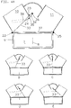
- FIGS 2, 3 and 4 it is shown that a schematic indicated fan wheel of a blower 7 by one Axis 8 is rotatably mounted in a housing 9. Furthermore are an end portion of a fresh air duct 10 and a circulating air duct 11 as well as the housing 9 cut shown. Via the fresh air duct 10 Outside air can be sucked in by the fan 7, whereas by the Recirculation duct 11 Air sucked in from the vehicle interior can be.
- a fresh air recirculation flap 12 is shown which during the movement between the fresh air duct 10 closing position ( Figure 1A) and the the air duct 11 closing position ( Figure 1E) in two blower distant provided scenery guides 13, 14 out becomes.
- the link guide 13 consists of approximately in the plane of the flap 12, linear backdrop 15, which is part of the flap 12 itself.
- One each Pin 16 of the housing 9 protrudes on both sides of the flap 12 in the slide 15 into it, so that the flap 12 to the Pin 16 pivotally and slidably "floating" mounted is.
- On both sides of the part of the flap 12 remote from the blower pins 17 are provided, which are approximately in the shape of a circular ring Guide tracks 18 of the housing 9 out be, the backdrop tracks 18 for backdrop management 14 belong.
- the backdrop tracks 18 are designed such that the free end of the flap 12 is approximately the desired one linear movement along the fan wheel contour.
- An adjustment device (adjustment motor, Bowden cable ...) with a crank-shaped pivotable about an axis 19 Adjustment element 20 moves the pin 17 of the flap 12 Activation by the backdrop 18.
- the free end of the Flap 12 moves along that in Figures 2B to E. shown line 21. It is clear that the flap 12th shortly before the individual air intake ducts are closed 10, 11 approximately linear in the direction of the flap plane emotional. This is achieved in that the backdrop track 18 in their end sections in alignment with the channel walls and the pin 16 extends. A movement of the Flap 12 by different pressure ratios and behind the flap 12 is excluded. Seals 22 to 25, which are arranged on the flap 12 or on the housing 9 are during the closing movement of the flap 12 compresses without significant friction, as is the case when flaps by pure Pivotal movement can be transferred to the closed position.
- the arrangement of a fresh air recirculation flap 26 according to the figure 3 is comparable to that of Figure 2.
- the flap 26 is designed as a crank Adjustment element 27 guided on a circular path 28. It is pivotable about an axis 29 on the adjusting element 27 stored.
- the adjustment element 27 becomes the flap 26, which is a sliding track 30 includes, again guided on a pin 31 fixed to the housing. The free end of the flap 26 moves along line 32 shown in Figures 3B-E.
- FIG. 4 there is again a Fresh air recirculation flap 33 via a fan guide remote from the fan 34 performed, with a backdrop 35 part the flap 33 is.
- the flap is on a housing-fixed Pin 36 pivotable and displaceable "floating" stored.
- a second slide track 37 runs parallel to the outer contour of the blower 7 in the housing 9 across the entire width (diameter) of the blower.
- the flap 33 mounted so that the flap 33 in the Slide 37 is pivotable and slidable.
- Cones the flap 33 can be formed, for example, as a groove Slide 37 can be stored.
- the adjusting element 38 is, for example, a Bowden cable educated.
- Air intake ducts 10, 11 to be arranged particularly aerodynamically. They can end up in the direct blower area without that tear-off edges have a negative effect.
- the flaps 12, 26, 33 are well sealable to the channels 10, 11 and stay safely in their closed position. Depending on what you want Comfort are different adjustment devices applicable, so that with little effort both purely mechanical as well as automated adjustment is feasible.
Landscapes
- Physics & Mathematics (AREA)
- Thermal Sciences (AREA)
- Engineering & Computer Science (AREA)
- Mechanical Engineering (AREA)
- Air-Conditioning For Vehicles (AREA)
- Air-Flow Control Members (AREA)
Description
- Figur 2A bis E:
- eine Heizungs- und Belüftungs- bzw. Klimaanlage nach der Erfindung mit in zwei gebläsefern angeordneten Kulissenbahnen geführter Frischluft-Umluft-Klappe, bei schematischer Darstellung mehrerer Klappenpositionen;
- Figur 3A bis E:
- eine Heizungs- und Belüftungs- bzw. Klimaanlage anderer Ausführung mit einer Frischluft-Umluft-Klappe, die in einer Kulissenbahn und an einer Kurbel geführt ist, bei schematischer Darstellung mehrerer Klappenpositionen;
- Figur 4A bis E:
- eine Heizungs- und Belüftungs- bzw. Klimaanlage anderer Ausführung mit in einer gebläsenahen und einer gebläsefernen Kulissenbahn geführter Frischluft-Umluft-Klappe, bei schematischer Darstellung mehrerer Klappenpositionen.
Claims (8)
- Heizungs- und Belüftungs- bzw. Klimaanlage für Kraftfahrzeuge mit einer Frischluft-Umluft-Klappe (12; 26; 33) zum wahlweisen Öffnen und Verschließen von Luftansaugkanälen (10, 11), durch die entweder Frischluft oder Umluft von einem Gebläse (7) ansaugbar ist, wobei die Luftansaugkanäle (10, 11) nahe einer Ansaugöffnung des Gebläses (7) in einem Gehäuse (9) enden, dadurch gekennzeichnet, daß die Klappe (12; 26; 33) einteilig ausgeführt, in zumindest einer Kulissenführung (13, 14; 34) verschwenk- und verschiebbar im Gehäuse (9) gelagert ist und beim Verstellen eine kombinierte rotatorische und translatorische Bewegung ausführt, wobei ein. Ende der Klappe (12; 26; 33) sich ständig sehr nahe am Gebläse (7) entlang bewegt.
- Heizungs- und Belüftungs- bzw. Klimaanlage nach Anspruch 1, dadurch gekennzeichnet, daß die Kulissenführung (13; 14; 34) derart ausgebildet ist, daß sich das Ende der Klappe (12; 26; 33) auf einer annähernd linearen Bahn (21; 32) bewegt.
- Heizungs- und Belüftungs- bzw. Klimaanlage nach Anspruch 1 und 2, gekennzeichnet durch eine Kulissenführung (13; 34) mit zumindest einer Kulissenbahn (15; 30; 35) als Bestandteil der Klappe (12; 26; 33), wobei die Kulissenbahn (15; 30; 35) annähernd in einer Klappenebene linear verläuft und die Klappe (12; 26; 33) an zumindest einem in der Kulissenbahn (15; 30; 35) geführten Zapfen (16; 31; 36) des Gehäuses (9) gelagert ist.
- Heizungs- und Belüftungs- bzw. Klimaanlage nach den Ansprüchen 1 bis 3, gekennzeichnet durch eine zweite Kulissenführung für die Klappe (33), die aus zumindest einer gebläsenahen, annähernd linear und parallel zur Gebläsekontur verlaufenden Kulissenbahn (37) besteht, in der ein Zapfen der Klappe (33) verschwenk- und verschiebbar gelagert ist.
- Heizungs- und Belüftungs- bzw. Klimaanlage nach den Ansprüchen 1 bis 3, gekennzeichnet durch eine zweite Kulissenführung (14) für die Klappe (12), die aus zumindest einer gebläsefernen Kulissenbahn (18) im Gehäuse (9) besteht, welche annähernd die Form eines Kreisringsektors aufweist und in der ein Zapfen (17) der Klappe (12) verschwenk- und verschiebbar gelagert ist.
- Heizungs- und Belüftungs- bzw. Klimaanlage nach zumindest einem der Ansprüche 1 bis 5, dadurch gekennzeichnet, daß ein rotatorisch um eine Achse (19) bewegliches Verstellelement (20; 27) einer Verstellvorrichtung im Abstand zu der Achse (19) gelenkig mit der Klappe (12; 26) verbunden ist.
- Heizungs- und Belüftungs- bzw. Klimaanlage nach zumindest einem der Ansprüche 1 bis 5, dadurch gekennzeichnet, daß ein Verstellelement (38) einer Verstellvorrichtung im Abstand zu einer Schwenkachse der Klappe (33) an der Klappe (33) gehaltert ist und die Klappe (33) über das Verstellelement (38) mit Kräften beaufschlagbar ist, wodurch die Klappe(33) in ihre Sollposition gezogen/gedrückt wird.
- Heizungs- und Belüftungs- bzw. Klimaanlage nach den Ansprüchen 1 bis 7, dadurch gekennzeichnet, daß die Kulissenführung (13; 14) derart ausgebildet ist, daß die Klappe (12; 26) kurz vor dem Verschließen eines der Luftansaugkanäle (10, 11) eine annähernd lineare Bewegung in Richtung einer Klappenebene ausführt.
Applications Claiming Priority (2)
| Application Number | Priority Date | Filing Date | Title |
|---|---|---|---|
| DE19509318 | 1995-03-15 | ||
| DE19509318A DE19509318A1 (de) | 1995-03-15 | 1995-03-15 | Heizungs- und Belüftungs- bzw. Klimaanlage für Kraftfahrzeuge |
Publications (2)
| Publication Number | Publication Date |
|---|---|
| EP0732231A1 EP0732231A1 (de) | 1996-09-18 |
| EP0732231B1 true EP0732231B1 (de) | 1998-12-16 |
Family
ID=7756704
Family Applications (1)
| Application Number | Title | Priority Date | Filing Date |
|---|---|---|---|
| EP96103319A Expired - Lifetime EP0732231B1 (de) | 1995-03-15 | 1996-03-04 | Heizungs- und Belüftungs- bzw. Klimaanlage für Kraftfahrzeuge |
Country Status (3)
| Country | Link |
|---|---|
| EP (1) | EP0732231B1 (de) |
| DE (2) | DE19509318A1 (de) |
| ES (1) | ES2125070T3 (de) |
Cited By (2)
| Publication number | Priority date | Publication date | Assignee | Title |
|---|---|---|---|---|
| EP1205320A2 (de) | 2000-11-09 | 2002-05-15 | Behr GmbH & Co. | Strömungskanalklappe |
| EP1247667A2 (de) | 2001-04-06 | 2002-10-09 | Behr GmbH & Co. | Strömungsklappe |
Families Citing this family (8)
| Publication number | Priority date | Publication date | Assignee | Title |
|---|---|---|---|---|
| FR2763286B1 (fr) * | 1997-05-14 | 1999-07-30 | Valeo Climatisation | Dispositif de reglage d'air pour vehicule automobile |
| FR2766130B1 (fr) * | 1997-07-15 | 1999-09-10 | Valeo Climatisation | Dispositif de ventilation d'un habitacle, notamment de vehicule automobile, a debit d'air exterieur controle par des moyens d'entrainement mecaniques |
| DE10027284A1 (de) * | 2000-05-31 | 2001-12-06 | Behr Gmbh & Co | Einrichtung zum Verschwenken einer Klappe |
| FR2812244B1 (fr) * | 2000-07-28 | 2003-01-31 | Valeo Climatisation | Dispositif de distribution d'un flux d'air equipe d'un volet articule |
| NL1019222C2 (nl) * | 2001-10-24 | 2003-04-28 | Tno | Tweewegklep, alsmede een ventilatiesysteem van een voertuig. |
| DE10232422A1 (de) * | 2002-07-17 | 2004-01-29 | Valeo Klimasysteme Gmbh | Luftklappenanordnung |
| FR2851502B1 (fr) * | 2003-02-26 | 2006-06-23 | Valeo Climatisation | Dispositif de controle d'un flux d'air, notamment pour un appareil de chauffage et/ou de climatisation d'un vehicule automobile |
| CN106765856A (zh) * | 2015-11-23 | 2017-05-31 | 青岛海尔空调电子有限公司 | 多模式空调送风方法和立式空调器 |
Family Cites Families (6)
| Publication number | Priority date | Publication date | Assignee | Title |
|---|---|---|---|---|
| GB1293793A (en) * | 1969-04-28 | 1972-10-25 | Chrysler United Kingdom Ltd Fo | Improvements in or relating to valves |
| DE3226438C2 (de) * | 1982-07-15 | 1987-03-19 | Bayerische Motoren Werke AG, 8000 München | Steuervorrichtung für die Luftströmung in Heiz- und/oder Klimaanlagen von Kraftfahrzeugen |
| DE3244729A1 (de) * | 1982-12-03 | 1984-06-07 | Dr.Ing.H.C. F. Porsche Ag, 7000 Stuttgart | Luftausstroemeinrichtung fuer die luftzufuhr in den innenraum eines fahrzeuges |
| KR850004048A (ko) * | 1983-11-04 | 1985-07-01 | 미다 가쓰시게 | 자동차용 공기조화장치의 공기 도입 장치 |
| JPH03281423A (ja) * | 1990-03-30 | 1991-12-12 | Nippondenso Co Ltd | 空気調和装置 |
| DE4401012A1 (de) * | 1993-01-28 | 1994-08-04 | Volkswagen Ag | Klappenanordnung, insbesondere für ein Wärmetauschergehäuse einer Kraftfahrzeugheizung |
-
1995
- 1995-03-15 DE DE19509318A patent/DE19509318A1/de not_active Withdrawn
-
1996
- 1996-03-04 DE DE59600983T patent/DE59600983D1/de not_active Expired - Lifetime
- 1996-03-04 EP EP96103319A patent/EP0732231B1/de not_active Expired - Lifetime
- 1996-03-04 ES ES96103319T patent/ES2125070T3/es not_active Expired - Lifetime
Cited By (4)
| Publication number | Priority date | Publication date | Assignee | Title |
|---|---|---|---|---|
| EP1205320A2 (de) | 2000-11-09 | 2002-05-15 | Behr GmbH & Co. | Strömungskanalklappe |
| DE10056670A1 (de) * | 2000-11-09 | 2002-05-16 | Behr Gmbh & Co | Strömungskanalklappe |
| EP1247667A2 (de) | 2001-04-06 | 2002-10-09 | Behr GmbH & Co. | Strömungsklappe |
| DE10118497A1 (de) * | 2001-04-06 | 2002-10-17 | Behr Gmbh & Co | Strömungsklappe |
Also Published As
| Publication number | Publication date |
|---|---|
| DE59600983D1 (de) | 1999-01-28 |
| EP0732231A1 (de) | 1996-09-18 |
| ES2125070T3 (es) | 1999-02-16 |
| DE19509318A1 (de) | 1996-09-19 |
Similar Documents
| Publication | Publication Date | Title |
|---|---|---|
| DE102017113906B4 (de) | Luftausströmer | |
| DE3323176C2 (de) | Heiz- und Belüftungseinrichtung für den Fahrgastraum von Kraftfahrzeugen | |
| DE4414036A1 (de) | Lufteintritt für eine Heizungs- oder Klimaanlage eines Kraftfahrzeugs | |
| WO2017182318A1 (de) | Luftausströmer mit einer einrichtung zum steuern eines luftstroms | |
| EP0888916A2 (de) | Lamellensystem für Belüftungseinrichtungen zur Regelung des Luftstroms, insbesondere für Belüftungen in Kraftfahrzeugen | |
| DE102017120417A1 (de) | Luftausströmer mit einstellbarer Luftaustrittsrichtung, insbesondere Flach- oder Fugenausströmer | |
| DE102008050180A1 (de) | Luftauslassdüse | |
| EP0732231B1 (de) | Heizungs- und Belüftungs- bzw. Klimaanlage für Kraftfahrzeuge | |
| DE102016122142B4 (de) | Luftausströmer | |
| DE102018110080A1 (de) | Luftausströmer | |
| EP0102611A2 (de) | Heiz- und/oder Klimaanlage für Kraftfahrzeuge | |
| DE102019106871A1 (de) | Luftausströmer | |
| EP1270286B1 (de) | Luftleitvorrichtung, insbesondere eines Fahrzeugs | |
| DE102019105409A1 (de) | Luftausströmer für ein fahrzeug sowie belüftungssystem mit solch einem luftausströmer | |
| EP1331116A2 (de) | Luftdüse | |
| DE69821452T2 (de) | Konstruktion eines öffnungsfähigen Fahrzeugdaches | |
| DE102018110093A1 (de) | Luftausströmer | |
| DE69208663T2 (de) | Radiallüfter | |
| DE102022111454A1 (de) | Luftausströmer mit einstellbarer Luftaustrittsrichtung, insbesondere Flach- oder Fugenausströmer | |
| DE19919975C1 (de) | Klimaanlage für eine Fahrgastzelle eines Fahrzeugs | |
| EP0655587B1 (de) | Zuluftgerät | |
| DE3226438C2 (de) | Steuervorrichtung für die Luftströmung in Heiz- und/oder Klimaanlagen von Kraftfahrzeugen | |
| DE102016122138A1 (de) | Luftausströmer | |
| DE102019132921A1 (de) | Luftausströmer mit Bedieneinrichtung | |
| DE10053814B4 (de) | Luftklappe für eine Lüftungs-, Heizungs- oder Klimaanlage eines Kraftfahrzeuges |
Legal Events
| Date | Code | Title | Description |
|---|---|---|---|
| PUAI | Public reference made under article 153(3) epc to a published international application that has entered the european phase |
Free format text: ORIGINAL CODE: 0009012 |
|
| AK | Designated contracting states |
Kind code of ref document: A1 Designated state(s): DE ES FR GB |
|
| 17P | Request for examination filed |
Effective date: 19961118 |
|
| GRAG | Despatch of communication of intention to grant |
Free format text: ORIGINAL CODE: EPIDOS AGRA |
|
| GRAG | Despatch of communication of intention to grant |
Free format text: ORIGINAL CODE: EPIDOS AGRA |
|
| GRAH | Despatch of communication of intention to grant a patent |
Free format text: ORIGINAL CODE: EPIDOS IGRA |
|
| 17Q | First examination report despatched |
Effective date: 19980522 |
|
| GRAH | Despatch of communication of intention to grant a patent |
Free format text: ORIGINAL CODE: EPIDOS IGRA |
|
| GRAA | (expected) grant |
Free format text: ORIGINAL CODE: 0009210 |
|
| AK | Designated contracting states |
Kind code of ref document: B1 Designated state(s): DE ES FR GB |
|
| ET | Fr: translation filed | ||
| REF | Corresponds to: |
Ref document number: 59600983 Country of ref document: DE Date of ref document: 19990128 |
|
| GBT | Gb: translation of ep patent filed (gb section 77(6)(a)/1977) |
Effective date: 19990107 |
|
| REG | Reference to a national code |
Ref country code: ES Ref legal event code: FG2A Ref document number: 2125070 Country of ref document: ES Kind code of ref document: T3 |
|
| PLBE | No opposition filed within time limit |
Free format text: ORIGINAL CODE: 0009261 |
|
| STAA | Information on the status of an ep patent application or granted ep patent |
Free format text: STATUS: NO OPPOSITION FILED WITHIN TIME LIMIT |
|
| 26N | No opposition filed | ||
| REG | Reference to a national code |
Ref country code: GB Ref legal event code: IF02 |
|
| REG | Reference to a national code |
Ref country code: GB Ref legal event code: 732E Free format text: REGISTERED BETWEEN 20090219 AND 20090225 |
|
| REG | Reference to a national code |
Ref country code: GB Ref legal event code: 732E Free format text: REGISTERED BETWEEN 20090305 AND 20090311 |
|
| REG | Reference to a national code |
Ref country code: GB Ref legal event code: 732E Free format text: REGISTERED BETWEEN 20091029 AND 20091104 |
|
| REG | Reference to a national code |
Ref country code: GB Ref legal event code: 732E Free format text: REGISTERED BETWEEN 20091105 AND 20091111 |
|
| REG | Reference to a national code |
Ref country code: DE Ref legal event code: R081 Ref document number: 59600983 Country of ref document: DE Owner name: GM GLOBAL TECHNOLOGY OPERATIONS LLC (N. D. GES, US Free format text: FORMER OWNER: GM GLOBAL TECHNOLOGY OPERATIONS, INC., DETROIT, MICH., US Effective date: 20110323 Ref country code: DE Ref legal event code: R081 Ref document number: 59600983 Country of ref document: DE Owner name: GM GLOBAL TECHNOLOGY OPERATIONS LLC (N. D. GES, US Free format text: FORMER OWNER: GM GLOBAL TECHNOLOGY OPERATIONS, INC., DETROIT, US Effective date: 20110323 |
|
| PGFP | Annual fee paid to national office [announced via postgrant information from national office to epo] |
Ref country code: FR Payment date: 20110317 Year of fee payment: 16 |
|
| PGFP | Annual fee paid to national office [announced via postgrant information from national office to epo] |
Ref country code: DE Payment date: 20110302 Year of fee payment: 16 Ref country code: GB Payment date: 20110302 Year of fee payment: 16 Ref country code: ES Payment date: 20110414 Year of fee payment: 16 |
|
| GBPC | Gb: european patent ceased through non-payment of renewal fee |
Effective date: 20120304 |
|
| REG | Reference to a national code |
Ref country code: FR Ref legal event code: ST Effective date: 20121130 |
|
| PG25 | Lapsed in a contracting state [announced via postgrant information from national office to epo] |
Ref country code: GB Free format text: LAPSE BECAUSE OF NON-PAYMENT OF DUE FEES Effective date: 20120304 Ref country code: FR Free format text: LAPSE BECAUSE OF NON-PAYMENT OF DUE FEES Effective date: 20120402 |
|
| REG | Reference to a national code |
Ref country code: DE Ref legal event code: R119 Ref document number: 59600983 Country of ref document: DE Effective date: 20121002 |
|
| REG | Reference to a national code |
Ref country code: ES Ref legal event code: FD2A Effective date: 20130710 |
|
| PG25 | Lapsed in a contracting state [announced via postgrant information from national office to epo] |
Ref country code: ES Free format text: LAPSE BECAUSE OF NON-PAYMENT OF DUE FEES Effective date: 20120305 |
|
| PG25 | Lapsed in a contracting state [announced via postgrant information from national office to epo] |
Ref country code: DE Free format text: LAPSE BECAUSE OF NON-PAYMENT OF DUE FEES Effective date: 20121002 |