EP0734648B1 - Luftröhren für Melkzeug - Google Patents
Luftröhren für Melkzeug Download PDFInfo
- Publication number
- EP0734648B1 EP0734648B1 EP96302130A EP96302130A EP0734648B1 EP 0734648 B1 EP0734648 B1 EP 0734648B1 EP 96302130 A EP96302130 A EP 96302130A EP 96302130 A EP96302130 A EP 96302130A EP 0734648 B1 EP0734648 B1 EP 0734648B1
- Authority
- EP
- European Patent Office
- Prior art keywords
- air
- air fork
- fork
- legs
- bight
- Prior art date
- Legal status (The legal status is an assumption and is not a legal conclusion. Google has not performed a legal analysis and makes no representation as to the accuracy of the status listed.)
- Expired - Lifetime
Links
- 210000002445 nipple Anatomy 0.000 claims description 57
- 239000008267 milk Substances 0.000 claims description 35
- 235000013336 milk Nutrition 0.000 claims description 35
- 210000004080 milk Anatomy 0.000 claims description 35
- 210000000078 claw Anatomy 0.000 claims description 24
- 230000010349 pulsation Effects 0.000 claims description 13
- 235000013365 dairy product Nutrition 0.000 claims description 8
- 210000000481 breast Anatomy 0.000 claims description 5
- 230000003797 telogen phase Effects 0.000 description 8
- 239000008280 blood Substances 0.000 description 2
- 210000004369 blood Anatomy 0.000 description 2
- 230000001351 cycling effect Effects 0.000 description 2
- 210000001364 upper extremity Anatomy 0.000 description 2
- 208000027418 Wounds and injury Diseases 0.000 description 1
- 230000000712 assembly Effects 0.000 description 1
- 238000000429 assembly Methods 0.000 description 1
- 230000000903 blocking effect Effects 0.000 description 1
- 230000017531 blood circulation Effects 0.000 description 1
- 230000006378 damage Effects 0.000 description 1
- 210000000003 hoof Anatomy 0.000 description 1
- 208000014674 injury Diseases 0.000 description 1
- 238000012986 modification Methods 0.000 description 1
- 230000004048 modification Effects 0.000 description 1
- 229910001220 stainless steel Inorganic materials 0.000 description 1
- 239000010935 stainless steel Substances 0.000 description 1
Images


Classifications
-
- A—HUMAN NECESSITIES
- A01—AGRICULTURE; FORESTRY; ANIMAL HUSBANDRY; HUNTING; TRAPPING; FISHING
- A01J—MANUFACTURE OF DAIRY PRODUCTS
- A01J5/00—Milking machines or devices
- A01J5/04—Milking machines or devices with pneumatic manipulation of teats
- A01J5/041—Milk claw
Definitions
- the invention relates to dairy equipment, and more particularly to milking clusters according to claim 1 and air forks for such milking clusters according to claim 11.
- a milking cluster is an assembly attached to the dairy animal's udder during milking.
- the cluster includes a claw, four shell assemblies, four short milk tubes, four air tubes, and an air fork.
- Each shell assembly includes an outer shell and an inner liner called an inflation.
- the short milk tube connects the inflation to the claw which in turn is connected to a milk transport hose subject to vacuum or negative pressure.
- the air tube connects the space between the inflation and the shell to the air fork.
- the air fork is connected through one or more air lines to a pulsation device cycling vacuum off and on.
- the inside bore of the inflation is at the system vacuum level, and the space between the inflation and the shell is either at vacuum or at atmospheric pressure depending on the cycle of the pulsation device.
- the vacuum on the inside of the inflation causes the inflation to collapse. This is known as the rest phase, during which there is no milk flow, i.e. liner closed.
- the rest phase during which there is no milk flow, i.e. liner closed.
- This is the milk phase during which milk flows, i.e. liner open.
- Most milking clusters operate efficiently with pulsation rates between 45 and 60 cycles per minute.
- the pulsing movement massages the teat.
- the collapse of the inflation squeezes the teat, forcing blood in the teat to circulate. Without this rest phase, blood would not circulate throughout the teat, and injury to the teat might result.
- the milk phase and the rest phase may have some overlap.
- the purpose of the air fork is to distribute the vacuum and atmospheric air pulses to the shells, to apply the cycling vacuum and atmospheric air pulses to the space between the inflation and the shell.
- Pulsation systems are either simultaneous (sometimes call single shot) or alternating. Simultaneous means that all four teat cups will be in either the milk phase or the rest phase at the same time. Alternating pulsation systems will have the two front teat cups in the milk phase and the two rear teat cups in the rest phase at one time, and then alternate to just the opposite. Alternating pulsators are usually more desirable because they provide more even milk flow, excellent vacuum stability, and the option of adjusting the two rear teat cups to a greater milk/rest ratio than the two front teat cups.
- Fig. 1 is a side view of a milking cluster attached to a dairy animal, as known in the prior art.
- Fig. 2 is an enlarged view of the milking cluster of Fig. 1.
- Fig. 3 is a view taken along line 3-3 of Fig. 2.
- Fig. 4 is a view taken along line 4-4 of Fig. 2.
- Fig. 5 is an isometric view of an air fork known in the prior art.
- Fig. 6 is a side view like Fig. 2 but illustrating the present invention.
- Fig. 7 is a view taken along line 7-7 of Fig. 6.
- Fig. 8 is a view taken along line 8-8 of Fig. 6.
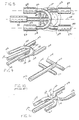
- Fig. 9 is an isometric view of an air fork in accordance with the present invention.
- Fig. 10 is an isometric view showing another air fork known in the prior art.
- Fig. 11 is an isometric view showing an alternate embodiment of an air fork in accordance with the present invention.
- US-A-3,072,096 describes a milking claw in the form of a one-piece elongated body provided with a lengthwise main milk channel.
- the inner ends of milk tubes nipples communicate with this channel, the nipples being disposed at 45-60° angles with respect to the channel.
- Also provided in the body is a lengthwise passage for air, along with nipples adapted to be connected with air tubes and communicating with the air passage.
- the air tube nipples are also inclined at an angle with respect to the lengthwise direction of the body, and are all directed in the same direction.
- Figs. 1-3 show a milking cluster 20 known in the prior art, and for which further reference may be had to U.S. Patents 4,530,307, 4,537,152, 5,178,095, and 5,218,924,.
- Dairy animal 22, such as a cow has an udder 24 and a plurality of teats 26, 28, 30, 32.
- the animal has a backbone 34 defining an axially extending longitudinal direction.
- a milking claw 36 has a plurality of inlets 38, 40, 42, 44, and an outlet 46.
- the claw lies along a central longitudinal axis 48 extending between the animal's front legs 31 and 33 and between the animal's rear legs 35 and 37 and generally parallel to backbone 34.
- Teat cups 50, 52, 54, 56 are each connected to a respective teat 26, 28, 30, 32 of udder 24.
- Short milk tubes 58, 60, 62, 64 each connect a respective claw inlet to a respective teat cup.
- An air fork 66, Figs. 2-5, has outlets 68, 70, 72, 74, and one or more inlets 76, 78.
- Air tubes 80, 82, 84, 86 each connect a respective air fork outlet to a respective teat cup.
- a milk hose 88 is connected to claw outlet 46.
- One or more vacuum pulsation air lines 90, 92 are connected to respective air fork inlets 76, 78.
- the claw has an upper eye hook 94 with a first upper circular hole 96 for hanging the claw when not in use, and a lower oblong hole 98 loosely receiving air fork inlets 76, 78 extending therethrough.
- milk hose 88 and air lines 90, 92 extend forwardly and then laterally to the side, though the milk hose and the air lines may extend longitudinally rearwardly along axis 48 between the cow's rear legs 35 and 37, or longitudinally forwardly along axis 48 between the cow's front legs 31 and 33.
- the milking arrangement shown in Figs. 1-5 is of the above noted alternating pulsation type. While vacuum is applied through air line 92, atmospheric air pressure is applied through air line 90, and vice versa. During the portion of the cycle when vacuum is applied through air line 92, such vacuum is applied to air fork inlet 78 and through air fork outlets 68 and 70 to air tubes 80 and 82 to rear teat cups 50 and 52, such that rear teats 26 and 28 are in the milk phase, and milk flows from the rear teats through milk tubes 58 and 60 to claw inlets 38 and 40 for collection in claw 36 and discharge through outlet 46 and out through milk hose 88.
- the atmospheric air pressure in the space between the teat cup shells and their respective inflations causes a differential pressure across the inflation or liner due to the vacuum on the inside thereof, which in turn collapses the liner, blocking milk flow, and also squeezing and massaging the teat to force blood circulation, as above noted, and all as is known in the prior art. It is typical that air lines 90 and 92 will be alternated between their opposite vacuum and atmospheric air pressure states at a pulsation rate between 45 and 60 cycles per minute.
- the other type of pulsation system is the simultaneous or single shot type.
- the air fork such as 100, Fig. 10 has a singular inlet 102 communicating with each of four outlets 104, 106, 108, 110 connected respectively to air lines 80, 82, 84, 86, such that all four teat cups 50, 52, 54, 56 will be in either the milk phase or in the rest phase at the same time, as noted above, and all as is known in the prior art.
- inlet 102 is in communication with all four outlets 104, 106, 108, 110.
- inlet 76 is in communication with outlets 72 and 74, but not outlets 68 and 70; and inlet 78 is in communication with outlets 68 and 70, but not outlets 72 and 74.
- the teat cups remain attached to the cow's teats until the milking operation is completed. If the teat cup becomes detached from the teat during milking, there will be a rapid admission of air into the interior of the inflation through the now open mouth thereof which formerly received the teat. This rapid admission of air is undesirable.
- One cause of such detachment can occur when the cow lifts either of her rear legs and steps forward, because either of the dew claws 112 or 114, Fig. 3, on the inside of her legs can hook an air tube and pull the teat cup off the teat.
- Right rear dew claw 112 can hook right air tube 80 and/or 84, and pull teat cup 50 and/or 54 off the respective teat.
- Left rear dew claw 114 can hook left air tube 82 and/or 86, and pull teat cup 52 and/or 56 off the respective teat.
- Each air tube 80, 82, 84, 86 extends from its respective air fork outlet laterally outwardly of its respective milk tube 58, 60, 62, 64 into the path of movement of dew claw 112 or 114.
- Figs. 6-9 and 11 illustrate the present invention solving the noted problem, and use like reference numerals from the above figures where appropriate to facilitate understanding.
- Bends are provided in the air fork outlets to route the air tubes initially longitudinally, rather than laterally.
- each air tube 80, 82, 84, 86 remains laterally inward of its respective milk tube 58, 60, 62, 64, to provide a narrower profile, as seen by contrasting Fig. 7 against Fig. 3.
- the air fork outlets direct the air tubes laterally inwardly of the milk tubes, rather than outwardly of the milk tubes.
- the dew claw 112 or 114 on the inside of her leg will not hook an air tube 80, 82, 84, 86 and pull the respective teat cup off the teat.
- Air fork 120 has air fork outlets 122, 124, 126, 128 extending generally axially longitudinally, i.e. generally parallel to the cow's backbone 34, such that air tubes 80, 82, 84, 86 initially extend generally axially longitudinally therefrom.
- Air tubes 80, 82, 84, 86 are laterally between respective milk tubes 58, 60, 62, 64 and central longitudinal axis 48.
- Air fork outlets 122 and 124 extend axially longitudinally rearwardly from the air fork and are laterally spaced on opposite sides of central longitudinal axis 48.
- Air fork outlets 126 and 128 extend axially longitudinally forwardly from the air fork and are laterally spaced on opposite sides of central longitudinal axis 48.
- Air fork outlets 122 and 126 are colinear and point in opposite longitudinal directions along a right longitudinal axis 130 laterally spaced from central longitudinal axis 48.
- Air fork outlets 124 and 128 are colinear and point in opposite longitudinal directions along a left longitudinal axis 132 laterally spaced from central longitudinal axis 48 on the opposite side thereof from right longitudinal axis 130.
- Axes 48, 130 and 132 are substantially parallel.
- Air fork 120 includes a first U-shaped portion 134 having first and second legs providing outlets 122 and 124, which legs are joined by a central bight 136.
- the air fork includes a second U-shaped portion 138 having legs providing outlets 126 and 128, which legs are joined by a central bight 140.
- U-shaped portions 134 and 138 extend in opposite longitudinal directions, with legs 122 and 124 pointing rearwardly, and legs 126 and 128 pointing forwardly. Bights 136 and 140 extend laterally and are proximate each other.
- U-shaped portions 134 and 138 are overlapped, with bight 136 being forward of bight 140.
- the U-shaped portions are preferably stainless steel, and may be welded to each other.
- Bight 140 has a port 142 facing longitudinally forwardly.
- Air fork inlet 144 extends axially longitudinally forwardly from port 142 for connection to air line 90.
- Inlet 144 is laterally spaced between legs 126 and 128.
- Bight 136 has a port 146 facing longitudinally forwardly.
- Air fork inlet 148 extends axially longitudinally forwardly from port 146 for connection to air line 92.
- Inlet 148 is laterally spaced between legs 126 and 128.
- Air fork 120 is for use with the above noted alternating type pulsation system.
- Inlet 144 is in communication with outlets 126 and 128, but not outlets 122 and 124.
- Inlet 148 is in communication with outlets 122 and 124, but not outlets 126 and 128.
- FIG. 11 illustrates an alternate embodiment showing an air fork 150 for use in a simultaneous, or single shot, type pulsation system.
- Air fork inlet 152 is in communication with each of the four air fork outlets 154, 156, 158, 160.
- the air fork has a U-shaped portion 162 with a central bight 164 and legs 154 and 156 extending axially longitudinally rearwardly therefrom.
- the air fork has a second U-shaped portion 166 with a central bight 168 and legs 158 and 160 extending axially longitudinally forwardly therefrom. Bights 164 and 168 have a common passage 170 therebetween.
- the air fork has a singular air inlet 152 extending longitudinally forwardly and communicating with bights 164 and 166 and common passage 170, and laterally spaced between legs 158 and 160.
Landscapes
- Life Sciences & Earth Sciences (AREA)
- Animal Husbandry (AREA)
- Environmental Sciences (AREA)
- External Artificial Organs (AREA)
- Branch Pipes, Bends, And The Like (AREA)
Claims (15)
- Melkzeug für ein Milch gebendes Tier mit einem Euter und einer Anzahl von Zitzen sowie einem Rückgrat, das eine sich axial erstreckende Längsrichtung festlegt, mitdadurch gekennzeichnet, daß die ersten und dritten Luftverteilerauslässe (122, 126; 154, 158) im wesentlichen parallel zu der zentralen Längsachse (48) in gegenüberliegende Längsrichtungen zeigen, und daß die zweiten und vierten Luftverteilerauslässe (124, 128; 156, 160) im wesentlichen parallel zu der zentralen Längsachse (48) in gegenüberliegende Längsrichtungen zeigen,einem Milchsammelstück (36) mit einer Anzahl von Einlässen (38, 40, 42, 44) und einem Auslaß (46), wobei das Milchsammelstück im Gebrauch in der zentralen Längsachse (48) liegt, die zwischen den Beinen des Tieres und im wesentlichen parallel zu dem Rückgrat verläuft;einer Anzahl von Zitzenbechern (50, 52, 54, 56), die im Gebrauch jeweils mit einer Zitze verbunden werden können;einer Anzahl von Milchschläuchen (58, 60, 62, 64), die jeweils einen Milchsammelstückeinlaß mit dem entsprechenden Zitzenbecher verbinden;einem Luftverteiler (120; 150) mit einer Anzahl von Auslässen (122, 124, 126, 128; 154, 156, 158, 160) und einem oder mehreren Einlässen (144, 148; 152);einer Anzahl von Luftschläuchen (80, 82, 84, 86), die jeweils einen Luftverteilerauslaß mit dem jeweiligen Zitzenbecher verbinden;einem Milchschlauch (88), der mit dem Milchsammelstückauslaß verbunden ist; und miteiner oder mehreren Vakuumpulsationsluftleitungen (90, 92), die mit dem einen oder den mehreren Luftverteilereinlässen verbunden ist oder sind;wobei die Luftverteilerauslässe erste und zweite Luftverteilerauslässe (122, 124; 154, 156), die im Luftverteiler hinten und mit seitlichem Abstand auf den gegenüberliegenden Seiten der zentralen Längsachse (48) angeordnet sind, und dritte und vierte Luftverteilerauslässe (126, 128; 158, 160) umfassen, die im Luftverteiler vorne angeordnet und mit seitlichem Abstand auf den gegenüberliegenden Seiten der zentralen Längsachse (48) angeordnet sind,
wodurch die ersten (122; 154), zweiten (124; 156), dritten (126; 158) und vierten (128; 160) Luftverteilerauslässe die Luftschläuche so ausrichten, daß sie seitlich innerhalb der Milchschläuche verlaufen. - Melkzeug nach Anspruch 1, wobei sich die Luftschläuche jeweils von ihrem betreffenden Luftverteilerauslaß weg erstrecken und seitlich zwischen ihren jeweiligen Milchschläuchen und der zentralen Längsachse (48) verlaufen.
- Melkzeug nach Anspruch 1 oder Anspruch 2, wobei die ersten und dritten Luftverteilerauslässe (122, 126; 154, 158) kolinear und entlang einer rechten Längsachse (130) angeordnet sind, die im seitlichen Abstand von der zentralen Längsachse (48) verläuft, und wobei die zweiten und vierten Luftverteilerauslässe (124, 128; 156, 160) kolinear und entlang einer linken Längsachse (132) angeordnet sind, die im seitlichen Abstand von der zentralen Längsachse (48) auf der der rechten Längsachse (130) gegenüberliegenden Seite verläuft.
- Melkzeug nach einem der vorhergehenden Ansprüche, wobei der Luftverteiler (120; 150) umfaßteinen ersten U-förmigen Abschnitt (134; 162) mit ersten (122; 154) und zweiten (124; 156) Schenkeln, die über eine erste zentrale Basis (136; 164) verbunden sind, wobei der erste Schenkel für den ersten Luftverteilerauslaß vorgesehen ist und der zweite Schenkel für den zweiten Luftverteilerauslaß; undeinen zweiten U-förmigen Abschnitt (138; 166) mit dritten (126; 158) und vierten (128; 160) Schenkeln, die über eine zweite zentrale Basis (140; 168) verbunden sind, wobei der dritte Schenkel für den dritten Luftverteilerauslaß vorgesehen ist und der vierte Schenkel für den vierten Luftverteilerauslaß.
- Melkzeug nach Anspruch 4, wobei sich die ersten und die zweiten U-förmigen Abschnitte (136, 138; 162, 166) in gegenüberliegende Längsrichtungen erstrecken, wobei die ersten und zweiten Schenkel (122, 124; 154, 156) nach hinten zeigen und die dritten und vierten Schenkel (126, 128; 158, 160) nach vorn.
- Melkzeug nach Anspruch 5, wobei sich die erste und die zweite Basis (136, 140; 164, 168) seitlich erstrecken und nahe beieinander liegen.
- Melkzeug nach Anspruch 6, wobei sich die ersten und die zweiten U-förmigen Abschnitte (134, 138) überlappen, und wobei die erste Basis vor der zweiten Basis liegt.
- Melkzeug nach Anspruch 7, wobeisich der erste und zweite Schenkel (122, 124) von der ersten Basis (136) in Längsrichtung nach hinten erstrecken;die erste Basis (136) einen ersten Anschluß (146) aufweist, der in eine erste Längsrichtung zeigt;der eine oder die mehreren Luftverteilereinlässe (144, 148) einen ersten Luftverteilereinlaß (148) umfassen, der sich in der ersten Längsrichtung vom ersten Anschluß (146) weg erstreckt;sich der dritte und vierte Schenkel (126, 128) von der zweiten Basis (140) in Längsrichtung nach vorn erstrecken;die zweite Basis (140) einen zweiten Anschluß (142) aufweist, der in die erste Längsrichtung zeigt; und wobeider eine oder die mehreren Luftverteilereinlässe (144, 148) einen zweiten Luftverteilereinlaß (144) umfassen, der sich in der ersten Längsrichtung vom zweiten Anschluß weg erstreckt.
- Melkzeug nach Anspruch 6, wobeisich die ersten und zweiten Schenkel von der ersten Basis in Längsrichtung nach hinten erstrecken;sich die dritten und vierten Schenkel von der zweiten Basis in Längsrichtung nach vorn erstrecken;die erste und die zweite Basis durch einen gemeinsamen Durchgang dazwischen verbunden sind; und wobeider eine oder die mehreren Luftverteilereinlässe einen einzigen Luftverteilereinlaß umfassen, der sich in Längsrichtung erstreckt und der mit dem gemeinsamen Durchgang verbunden ist.
- Melkzeug nach Anspruch 9, wobei eine der Basen einen Anschluß aufweist, der in eine erste Längsrichtung zeigt, und wobei sich der Luftverteilereinlaß in Längsrichtung von dem Anschluß weg erstreckt.
- Luftverteiler für ein Melkzeug für ein Milch gebendes Tier mit einem Euter und einer Anzahl von Zitzen sowie einem eine sich axial erstreckende Längsrichtung festlegenden Rückgrat, wobei das Melkzeug ein Milchsammelstück (36) mit einer Anzahl von Einlässen (38, 40, 42, 44) und einem Auslaß (46), eine Anzahl von Zitzenbechern (50, 52, 54, 56), die im Gebrauch jeweils mit einer Zitze verbunden sind, eine Anzahl von Milchschläuchen, die jeweils einen Milchsammelstückeinlaß mit dem entsprechenden Zitzenbecher verbinden, eine Anzahl von Luftschläuchen (80, 82, 84, 86), die mit dem jeweiligen Zitzenbecher verbunden sind, einen Milchschlauch (88), der mit dem Milchsammelstückauslaß verbunden ist, und eine oder mehrere Vakuumpulsationsleitungen (90, 92) umfaßt,dadurch gekennzeichnet, daß die ersten (122; 154) und dritten (126; 158) Luftverteilerauslässe im wesentlichen parallel zu der zentralen Längsachse (48) in gegenüberliegende Längsrichtungen zeigen, und daß die zweiten (124; 156) und vierten (128; 160) Luftverteilerauslässe im wesentlichen parallel zu der zentralen Längsachse (48) in gegenüberliegende Längsrichtungen zeigen.wobei der Luftverteiler im Gebrauch in einer zentralen Längsachse liegt, die zwischen den Beinen des Tieres und im wesentlichen parallel zu dem Rückgrat verläuft, und wobei der Luftverteiler eine Anzahl von Auslässen (122, 124, 126, 128; 154, 156, 158, 160) zur Verbindung mit den Luftschläuchen und einen oder mehrere Einlässe (144, 148; 152) aufweist,wobei die Luftverteilerauslässe erste und zweite Luftverteilerauslässe (122, 124; 154, 156), die im Luftverteiler hinten und mit seitlichem Abstand auf den gegenüberliegenden Seiten der zentralen Längsachse (48) angeordnet sind, und dritte und vierte Luftverteilerauslässe (126, 128; 158, 160) umfassen, die im Luftverteiler vorne angeordnet und mit seitlichem Abstand auf den gegenüberliegenden Seiten der zentralen Längsachse (48) angeordnet sind,
- Luftverteiler nach Anspruch 11, wobei die ersten (122; 154) und dritten (126; 158) Luftverteilerauslässe kolinear und entlang einer rechten Längsachse (130) angeordnet sind, die im seitlichen Abstand von der zentralen Längsachse (48) verläuft, und wobei die zweiten (124; 156) und vierten (128; 160) Luftverteilerauslässe kolinear und entlang einer linken Längsachse (132) angeordnet sind, die im seitlichen Abstand von der zentralen Längsachse auf der der rechten Längsachse (130) gegenüberliegenden Seite verläuft.
- Luftverteiler nach Anspruch 11 oder 12, wobei der Luftverteiler (120; 150) umfaßteinen ersten U-förmigen Abschnitt (134; 162) mit ersten (122; 154) und zweiten (124; 156) Schenkeln, die über eine erste zentrale Basis (136; 164) verbunden sind, wobei der erste Schenkel für den ersten Luftverteilerauslaß vorgesehen ist und der zweite Schenkel für den zweiten Luftverteilerauslaß; undeinen zweiten U-förmigen Abschnitt (138; 166) mit dritten (126; 158) und vierten (128; 160) Schenkeln, die über eine zweite zentrale Basis (140; 168) verbunden sind, wobei der dritte Schenkel für den dritten Luftverteilerauslaß vorgesehen ist und der vierte Schenkel für den vierten Luftverteilerauslaß.
- Luftverteiler nach Anspruch 13, wobeisich die ersten und die zweiten U-förmigen Abschnitte (136, 138) in gegenüberliegende Längsrichtungen erstrecken, wobei die ersten und zweiten Schenkel (122, 124) nach hinten zeigen und die dritten und vierten Schenkel (126, 128) nach vorn;sich die ersten und die zweiten Basen (136, 140) seitlich erstrecken und nahe beieinander liegen;sich die ersten und die zweiten U-förmigen Abschnitte (136, 138) überlappen, wobei die erste Basis (136) vor der zweiten Basis (140) liegt;sich der erste und zweite Schenkel (122, 124) von der ersten Basis (136) in Längsrichtung nach hinten erstreckt;die erste Basis (136) einen ersten Anschluß (146) aufweist, der in eine erste Längsrichtung zeigt;der eine oder die mehreren Luftverteilereinlässe (144, 148) einen ersten Luftverteilereinlaß (148) umfassen, der sich in der ersten Längsrichtung vom ersten Anschluß (146) weg erstreckt;sich der dritte und vierte Schenkel (126, 128) von der zweiten Basis (140) in Längsrichtung nach vorn erstrecken;die zweite Basis (140) einen zweiten Anschluß (142) aufweist, der in die erste Längsrichtung zeigt; undder eine oder die mehreren Luftverteilereinlässe (144, 148) einen zweiten Luftverteilereinlaß (144) umfassen, der sich in der ersten Längsrichtung vom zweiten Anschluß (142) weg erstreckt.
- Luftverteiler nach Anspruch 13, wobeisich die ersten und die zweiten U-förmigen Abschnitte (162, 166) in gegenüberliegende Längsrichtungen erstrecken, wobei die ersten und zweiten Schenkel (154. 156) nach hinten zeigen und die dritten und vierten Schenkel (158, 160) nach vorn;sich die ersten und zweiten Basen (164, 168) seitlich erstrecken und nahe beieinanderliegen;sich der erste und zweite Schenkel (154, 156) von der ersten Basis (164) in Längsrichtung nach hinten erstrecken;sich der dritte und vierte Schenkel (158, 160) von der zweiten Basis (168) in Längsrichtung nach hinten erstrecken;die erste und die zweite Basis (164, 168) durch einen gemeinsamen Durchgang (170) dazwischen verbunden sind; undder eine oder die mehreren Luftverteilereinlässe einen einzigen Luftverteilereinlaß (152) umfassen, der sich in Längsrichtung erstreckt und der mit dem gemeinsamen Durchgang verbunden ist.
Applications Claiming Priority (2)
| Application Number | Priority Date | Filing Date | Title |
|---|---|---|---|
| US411417 | 1995-03-27 | ||
| US08/411,417 US5586518A (en) | 1995-03-27 | 1995-03-27 | Milking cluster air fork |
Publications (2)
| Publication Number | Publication Date |
|---|---|
| EP0734648A1 EP0734648A1 (de) | 1996-10-02 |
| EP0734648B1 true EP0734648B1 (de) | 2001-05-30 |
Family
ID=23628834
Family Applications (1)
| Application Number | Title | Priority Date | Filing Date |
|---|---|---|---|
| EP96302130A Expired - Lifetime EP0734648B1 (de) | 1995-03-27 | 1996-03-27 | Luftröhren für Melkzeug |
Country Status (4)
| Country | Link |
|---|---|
| US (1) | US5586518A (de) |
| EP (1) | EP0734648B1 (de) |
| DE (1) | DE69613037T2 (de) |
| ES (1) | ES2158245T3 (de) |
Families Citing this family (22)
| Publication number | Priority date | Publication date | Assignee | Title |
|---|---|---|---|---|
| US6481986B1 (en) | 1995-08-03 | 2002-11-19 | Medela Holding Ag | Vacuum adjustment mechanism particularly adapted for a breastpump |
| US6257847B1 (en) | 1995-08-03 | 2001-07-10 | Medela, Inc. | Diaphragm pump and pump for double-breast pumping |
| SE511150C2 (sv) * | 1996-02-05 | 1999-08-09 | Alfa Laval Agri Ab | Spenkoppscentral |
| EP0800836B1 (de) * | 1996-04-14 | 2003-02-26 | Medela AG | Einrichtung zum Absaugen von Muttermilch |
| US6139521A (en) * | 1996-06-03 | 2000-10-31 | Medela Holding Ag | Breastpump having particular application as a small motorized pump capable of double-breast pumping |
| US5960738A (en) * | 1998-12-07 | 1999-10-05 | Dec International, Inc. | Milking cluster hose positioner |
| US6673036B1 (en) | 1999-10-13 | 2004-01-06 | The First Years Inc. | Pumping breast milk |
| IT250138Y1 (it) * | 2000-11-28 | 2003-07-24 | Interpuls Spa | Gruppo di mungitura con tubazioni corte del latte dotate di settilongitudinali interni |
| US6749582B2 (en) * | 2002-04-30 | 2004-06-15 | The First Years Inc. | Pumping breast milk |
| SE0201596D0 (sv) * | 2002-05-29 | 2002-05-29 | Delaval Holding Ab | A device for cleaning the teats of an animal |
| US7021239B2 (en) * | 2004-04-20 | 2006-04-04 | Bou-Matic Technologies Corp. | Milking claw top |
| US6981468B1 (en) | 2004-04-20 | 2006-01-03 | Bou-Matic Technologies Corp. | Milking claw bottom |
| US7396339B2 (en) * | 2004-04-30 | 2008-07-08 | The First Years Inc. | Pumping breast milk |
| RU2294630C2 (ru) * | 2005-04-06 | 2007-03-10 | Анатолий Александрович Ганеев | Низковакуумный доильный аппарат |
| RU2340167C1 (ru) * | 2007-03-29 | 2008-12-10 | Анатолий Александрович Ганеев | Способ машинного доения млекопитающих животных и низковакуумный доильный аппарат для осуществления способа |
| US8945046B2 (en) * | 2008-04-03 | 2015-02-03 | Lyndon Brittner | Hands-free breast pump system |
| WO2010083485A2 (en) | 2009-01-16 | 2010-07-22 | Learning Curve Brands, Inc. | Breast pump and method of use |
| US9968069B2 (en) * | 2011-03-18 | 2018-05-15 | Gea Farm Technologies Gmbh | Milking cluster and milking parlor having such a milking cluster |
| DE102011001404A1 (de) | 2011-03-18 | 2012-09-20 | Gea Farm Technologies Gmbh | Melkzeug und Melkstand mit einem solchen Melkzeug |
| DE102012110501A1 (de) | 2012-03-14 | 2013-09-19 | Gea Farm Technologies Gmbh | Platzteiler einer Melkstandanordnung und Melkstandanordnung |
| DE102012102133A1 (de) | 2012-03-14 | 2013-09-19 | Gea Farm Technologies Gmbh | Melkstandanordnung mit einer innenrobotervorrichtung |
| DE102014107124A1 (de) | 2014-05-20 | 2015-11-26 | Gea Farm Technologies Gmbh | Armeinrichtung für eine Melkstandanordnung zum automatischen Melken von milchgebenden Tieren, Platzteiler einer Melkstandanordnung und Melkstandanordnung |
Family Cites Families (10)
| Publication number | Priority date | Publication date | Assignee | Title |
|---|---|---|---|---|
| US3079891A (en) * | 1960-07-25 | 1963-03-05 | Bernard F Miller | Milking cup assembly |
| US3072096A (en) * | 1960-08-11 | 1963-01-08 | Norbert M Kluge | Claw for milking machines |
| US3776196A (en) * | 1972-04-19 | 1973-12-04 | J Luiz | Claw assembly for milking machines |
| US4530307A (en) * | 1982-10-06 | 1985-07-23 | Dec International, Inc. | Teat cup inflation |
| US4537152A (en) * | 1984-06-01 | 1985-08-27 | Dec International, Inc. | Milking claw |
| DE3679245D1 (de) * | 1985-07-19 | 1991-06-20 | Lely Nv C Van Der | Geraet zum melken von tieren, wie zum beispiel kuehen in einem stall. |
| US4941433A (en) * | 1988-05-23 | 1990-07-17 | Agri-Automation Company, Ltd. | Milking method and related apparatus |
| SU1667753A1 (ru) * | 1989-04-14 | 1991-08-07 | Украинский научно-исследовательский институт механизации и электрификации сельского хозяйства | Коллектор доильного аппарата |
| US5178095A (en) * | 1991-06-13 | 1993-01-12 | Dec International, Inc. | Milking system with positive pressure on thin liner |
| US5218924A (en) * | 1992-03-19 | 1993-06-15 | Dec International, Inc. | Milking system with variable pressure source |
-
1995
- 1995-03-27 US US08/411,417 patent/US5586518A/en not_active Expired - Lifetime
-
1996
- 1996-03-27 DE DE69613037T patent/DE69613037T2/de not_active Expired - Fee Related
- 1996-03-27 ES ES96302130T patent/ES2158245T3/es not_active Expired - Lifetime
- 1996-03-27 EP EP96302130A patent/EP0734648B1/de not_active Expired - Lifetime
Also Published As
| Publication number | Publication date |
|---|---|
| US5586518A (en) | 1996-12-24 |
| DE69613037T2 (de) | 2001-09-13 |
| DE69613037D1 (de) | 2001-07-05 |
| EP0734648A1 (de) | 1996-10-02 |
| ES2158245T3 (es) | 2001-09-01 |
Similar Documents
| Publication | Publication Date | Title |
|---|---|---|
| EP0734648B1 (de) | Luftröhren für Melkzeug | |
| EP1109438B1 (de) | Verfahren und vorrichtung zum reinigen des euters eines milchtiers | |
| AU2006257779B2 (en) | Liner contact automatic teat dip applicator | |
| US9439391B2 (en) | Dairy milking devices and methods | |
| US20040060520A1 (en) | Short milk tube | |
| EP1104986B1 (de) | Vorrichtung zum melken eines tiers | |
| US4807566A (en) | Milk claw | |
| US5752462A (en) | Teat cup inflation | |
| US7021239B2 (en) | Milking claw top | |
| EP0031246B1 (de) | Verfahren zum Melken von Tieren, Vorrichtung zur Verwendung bei Melkmaschinen und Melkmaschinen | |
| JP2002523202A (ja) | 二つの別個の流体のための容易に曲げることのできるチューブ | |
| US6981468B1 (en) | Milking claw bottom | |
| US3776196A (en) | Claw assembly for milking machines | |
| US4434744A (en) | Methods of and/or apparatus for milking animals | |
| EP1608217B1 (de) | Melkbechersatz und melkglied | |
| HU192216B (en) | Milking apparatus provided with collecting unit | |
| US3072096A (en) | Claw for milking machines | |
| RU2040161C1 (ru) | Аппарат для дойки коров | |
| EP1227716A1 (de) | Vorrichtung und verfahren für melkmaschinen | |
| US2045454A (en) | Combination pneumatic pulsator and milk claw |
Legal Events
| Date | Code | Title | Description |
|---|---|---|---|
| PUAI | Public reference made under article 153(3) epc to a published international application that has entered the european phase |
Free format text: ORIGINAL CODE: 0009012 |
|
| AK | Designated contracting states |
Kind code of ref document: A1 Designated state(s): DE ES FR GB IT |
|
| 17P | Request for examination filed |
Effective date: 19970311 |
|
| 17Q | First examination report despatched |
Effective date: 19990621 |
|
| GRAG | Despatch of communication of intention to grant |
Free format text: ORIGINAL CODE: EPIDOS AGRA |
|
| GRAG | Despatch of communication of intention to grant |
Free format text: ORIGINAL CODE: EPIDOS AGRA |
|
| GRAG | Despatch of communication of intention to grant |
Free format text: ORIGINAL CODE: EPIDOS AGRA |
|
| GRAH | Despatch of communication of intention to grant a patent |
Free format text: ORIGINAL CODE: EPIDOS IGRA |
|
| GRAH | Despatch of communication of intention to grant a patent |
Free format text: ORIGINAL CODE: EPIDOS IGRA |
|
| GRAA | (expected) grant |
Free format text: ORIGINAL CODE: 0009210 |
|
| AK | Designated contracting states |
Kind code of ref document: B1 Designated state(s): DE ES FR GB IT |
|
| REF | Corresponds to: |
Ref document number: 69613037 Country of ref document: DE Date of ref document: 20010705 |
|
| ET | Fr: translation filed | ||
| ITF | It: translation for a ep patent filed | ||
| REG | Reference to a national code |
Ref country code: ES Ref legal event code: FG2A Ref document number: 2158245 Country of ref document: ES Kind code of ref document: T3 |
|
| REG | Reference to a national code |
Ref country code: GB Ref legal event code: IF02 |
|
| PLBE | No opposition filed within time limit |
Free format text: ORIGINAL CODE: 0009261 |
|
| STAA | Information on the status of an ep patent application or granted ep patent |
Free format text: STATUS: NO OPPOSITION FILED WITHIN TIME LIMIT |
|
| 26N | No opposition filed | ||
| PGFP | Annual fee paid to national office [announced via postgrant information from national office to epo] |
Ref country code: GB Payment date: 20070216 Year of fee payment: 12 |
|
| PGFP | Annual fee paid to national office [announced via postgrant information from national office to epo] |
Ref country code: ES Payment date: 20070326 Year of fee payment: 12 |
|
| PGFP | Annual fee paid to national office [announced via postgrant information from national office to epo] |
Ref country code: DE Payment date: 20070330 Year of fee payment: 12 |
|
| PGFP | Annual fee paid to national office [announced via postgrant information from national office to epo] |
Ref country code: IT Payment date: 20070529 Year of fee payment: 12 |
|
| PGFP | Annual fee paid to national office [announced via postgrant information from national office to epo] |
Ref country code: FR Payment date: 20070301 Year of fee payment: 12 |
|
| GBPC | Gb: european patent ceased through non-payment of renewal fee |
Effective date: 20080327 |
|
| REG | Reference to a national code |
Ref country code: FR Ref legal event code: ST Effective date: 20081125 |
|
| PG25 | Lapsed in a contracting state [announced via postgrant information from national office to epo] |
Ref country code: DE Free format text: LAPSE BECAUSE OF NON-PAYMENT OF DUE FEES Effective date: 20081001 |
|
| PG25 | Lapsed in a contracting state [announced via postgrant information from national office to epo] |
Ref country code: FR Free format text: LAPSE BECAUSE OF NON-PAYMENT OF DUE FEES Effective date: 20080331 |
|
| REG | Reference to a national code |
Ref country code: ES Ref legal event code: FD2A Effective date: 20080328 |
|
| PG25 | Lapsed in a contracting state [announced via postgrant information from national office to epo] |
Ref country code: GB Free format text: LAPSE BECAUSE OF NON-PAYMENT OF DUE FEES Effective date: 20080327 |
|
| PG25 | Lapsed in a contracting state [announced via postgrant information from national office to epo] |
Ref country code: ES Free format text: LAPSE BECAUSE OF NON-PAYMENT OF DUE FEES Effective date: 20080328 |
|
| PG25 | Lapsed in a contracting state [announced via postgrant information from national office to epo] |
Ref country code: IT Free format text: LAPSE BECAUSE OF NON-PAYMENT OF DUE FEES Effective date: 20080327 |