EP0735308A1 - Safety guard system for machine having a ram - Google Patents
Safety guard system for machine having a ram Download PDFInfo
- Publication number
- EP0735308A1 EP0735308A1 EP96302143A EP96302143A EP0735308A1 EP 0735308 A1 EP0735308 A1 EP 0735308A1 EP 96302143 A EP96302143 A EP 96302143A EP 96302143 A EP96302143 A EP 96302143A EP 0735308 A1 EP0735308 A1 EP 0735308A1
- Authority
- EP
- European Patent Office
- Prior art keywords
- ram
- safety guard
- guard
- signal
- closed position
- Prior art date
- Legal status (The legal status is an assumption and is not a legal conclusion. Google has not performed a legal analysis and makes no representation as to the accuracy of the status listed.)
- Ceased
Links
- 230000000694 effects Effects 0.000 claims abstract description 10
- 230000005540 biological transmission Effects 0.000 claims 1
- 101100328887 Caenorhabditis elegans col-34 gene Proteins 0.000 description 11
- 238000002788 crimping Methods 0.000 description 10
- 239000000463 material Substances 0.000 description 9
- 230000008878 coupling Effects 0.000 description 4
- 238000010168 coupling process Methods 0.000 description 4
- 238000005859 coupling reaction Methods 0.000 description 4
- 208000014674 injury Diseases 0.000 description 4
- 208000027418 Wounds and injury Diseases 0.000 description 3
- 230000006378 damage Effects 0.000 description 3
- 238000004519 manufacturing process Methods 0.000 description 3
- 239000002184 metal Substances 0.000 description 2
- 239000004033 plastic Substances 0.000 description 2
- 208000012260 Accidental injury Diseases 0.000 description 1
- 230000005355 Hall effect Effects 0.000 description 1
- 230000004888 barrier function Effects 0.000 description 1
- 239000004020 conductor Substances 0.000 description 1
- 230000001351 cycling effect Effects 0.000 description 1
- 230000000977 initiatory effect Effects 0.000 description 1
- 239000004417 polycarbonate Substances 0.000 description 1
- 229920000515 polycarbonate Polymers 0.000 description 1
- 238000010408 sweeping Methods 0.000 description 1
Images


Classifications
-
- F—MECHANICAL ENGINEERING; LIGHTING; HEATING; WEAPONS; BLASTING
- F16—ENGINEERING ELEMENTS AND UNITS; GENERAL MEASURES FOR PRODUCING AND MAINTAINING EFFECTIVE FUNCTIONING OF MACHINES OR INSTALLATIONS; THERMAL INSULATION IN GENERAL
- F16P—SAFETY DEVICES IN GENERAL; SAFETY DEVICES FOR PRESSES
- F16P3/00—Safety devices acting in conjunction with the control or operation of a machine; Control arrangements requiring the simultaneous use of two or more parts of the body
- F16P3/001—Safety devices for guarding the human operator of punch presses or like machine tools performing an opening and closing travel
- F16P3/005—Safety devices for guarding the human operator of punch presses or like machine tools performing an opening and closing travel having a movable screen or a sensor influencing the switching system
-
- F—MECHANICAL ENGINEERING; LIGHTING; HEATING; WEAPONS; BLASTING
- F16—ENGINEERING ELEMENTS AND UNITS; GENERAL MEASURES FOR PRODUCING AND MAINTAINING EFFECTIVE FUNCTIONING OF MACHINES OR INSTALLATIONS; THERMAL INSULATION IN GENERAL
- F16P—SAFETY DEVICES IN GENERAL; SAFETY DEVICES FOR PRESSES
- F16P3/00—Safety devices acting in conjunction with the control or operation of a machine; Control arrangements requiring the simultaneous use of two or more parts of the body
- F16P3/12—Safety devices acting in conjunction with the control or operation of a machine; Control arrangements requiring the simultaneous use of two or more parts of the body with means, e.g. feelers, which in case of the presence of a body part of a person in or near the danger zone influence the control or operation of the machine
- F16P3/16—Safety devices acting in conjunction with the control or operation of a machine; Control arrangements requiring the simultaneous use of two or more parts of the body with means, e.g. feelers, which in case of the presence of a body part of a person in or near the danger zone influence the control or operation of the machine with feeling members moved by the machine
-
- Y—GENERAL TAGGING OF NEW TECHNOLOGICAL DEVELOPMENTS; GENERAL TAGGING OF CROSS-SECTIONAL TECHNOLOGIES SPANNING OVER SEVERAL SECTIONS OF THE IPC; TECHNICAL SUBJECTS COVERED BY FORMER USPC CROSS-REFERENCE ART COLLECTIONS [XRACs] AND DIGESTS
- Y10—TECHNICAL SUBJECTS COVERED BY FORMER USPC
- Y10T—TECHNICAL SUBJECTS COVERED BY FORMER US CLASSIFICATION
- Y10T74/00—Machine element or mechanism
- Y10T74/21—Elements
- Y10T74/2193—Guard mechanisms
- Y10T74/2194—Automatic
- Y10T74/2196—Reciprocating member actuator
Definitions
- the invention relates to the field of safety guards for power driven machines, and in particular, to a movable safety guard which improves access to the workstation of the machine between work cycles.
- Safety guards or barriers which shield the moving parts of a machine in order to prevent accidental injury are well known.
- a problem with safety guards is that they restrict essential access to the workstation of the machine such as is necessary for an operator to properly and efficiently position a workpiece in the workstation, thereby frustrating the operator and reducing production rates.
- U.S. Patent No. 4,060,160 to Lieber discloses a safety guard which is mounted to move with the ram of a machine.
- a safety interlock ensures that if a foreign object is encountered by the guard, machine operation will be terminated.
- the interlock utilizes the safety guard as a workpiece sensor and relies on a material property of the workpiece not normally exhibited by a body part, such as electrical conductivity. If the safety guard encounters an object without concurrently sensing the expected material property, power to the ram is cut off.
- a specific material property of the workpiece must be selected to be sensed, thereby requiring a sensor which is dedicated to the selected material property.
- the interlock may need to be customized with different sensors for different material properties of different workpieces.
- some workpieces may not readily lend themselves to being sensed through the safety guard.
- an insulated electrical conductor which is to have a terminal applied to a crimped end thereof is not readily differentiated from a foreign object based on a material property.
- a movable safety guard with a simple interlock system to ensure that the guard has closed prior to an operation being performed on a workpiece.
- This invention provides a safety guard system for a machine having a ram which is movable toward and away from a work zone and an actuator operable for driving the ram through a ram stroke toward the work zone.
- the safety guard system includes a safety guard mounted for movement along a guard path between open and closed positions with respect to the work zone.
- the safety guard is releasably coupled to the ram for movement during the ram stroke from the open to the closed position before completion of the ram stroke, and the safety guard is arranged to decouple from the ram upon either one of reaching the closed position or earlier encountering an obstruction in the guard path.
- a guard sensor effects a first signal upon the safety guard reaching the closed position, and an object sensor effects a second signal upon decoupling of the safety guard from the ram.
- a controller is responsive to the first and second signals such that the controller enables completion of the ram stroke upon receiving the first signal, and the controller terminates the ram stroke upon receiving the second signal prior to receiving the first signal.
- a safety guard system is shown in association with relevant portions of a terminal crimping machine which is operable for deforming a terminal 2 onto the end of a wire 3, although the safety guard system can be utilized on numerous other machines which have a ram movable through a ram stroke.
- the terminal crimping machine has a press ram 4 which is mounted for reciprocation with respect to a base 5.
- the press ram 4 is driven downwardly through a ram stroke by an actuator such as an electric motor (not shown) upon generation of an appropriate start signal which is typically initiated through a foot switch controlled by the machine operator.
- the press ram 4 has a slot 6 which receives a knob 7 of a terminal applicator shown generally as 8.
- the terminal applicator 8 includes an applicator ram 9 which carries an upper crimping die 10 which cooperates with a lower crimping die, or anvil, 11 to deform the terminal 2 tightly around the wire 3.
- the terminal applicator 8 receives terminals in strip form from a supply and automatically severs an individual terminal from the strip and feeds the severed terminal 2 to a work zone 12 above the anvil 11 with each cycle of the press ram 4.
- a complete description of such a terminal applicator 8 is contained in U.S. Patent No. 3,184,950 which is incorporated by reference as if set forth fully herein.
- the terminal crimping machine be substantially surrounded by an enclosure.
- the enclosure is preferably made from a clear polycarbonate plastic material.
- a section 14 of the enclosure is mounted on a hinge (not shown) to permit pivoting of the enclosure section 14 and thereby provide access to the machine for service during intervals between crimping cycles.
- An appropriate interlock may be provided to prevent cycling the machine when the enclosure section 14 is open.
- a window 15 defined by a cutout in the enclosure section 14 provides an opening through which the wire 3 may be introduced to the work zone 12 by the machine operator, who then generates the start signal to actuate the ram.
- FIG. 3 A prior art crimping machine without the safety guard of the present invention is shown in Fig. 3 with an enclosure section 94 having a window 95.
- Safety considerations dictate that the window 95 be dimensioned quite narrow to preclude any body part, including a finger, from being inserted into the work zone through the window.
- the window 95 includes a vertical section 96 and a horizontal slot 97 which extends to an exit 98 at a side edge of the enclosure section.
- the vertical section 96 has a width of approximately .25 inch (6.35 mm), and the portion of the slot 97 immediately adjacent to the vertical section has a height of similar dimension.
- the cutout can be significantly larger than would otherwise be acceptable because the safety guard system ensures that a foreign object in the work zone will be sensed and the crimping cycle will be halted before an injury can occur.
- the window 15 may now be approximately one inch high from upper edge 18 to lower edge 19, and approximately four inches wide from side edge 55 to side edge 57, thus permitting the machine operator to sweep and maneuver the wires through the work zone at a rapid rate, and to withdraw the wires through passageway 59 between sides 61 and 63.
- the invention comprises a safety guard shown generally as 20 which includes a shutter section 22 and a slide section 24.
- the shutter section 22 is preferably made from a clear plastic material while the slide section 24 is preferably formed from a metal strip material.
- the shutter section 22 and the slide section 24 are coupled together such as by threaded fasteners 25 for movement as an integral safety guard unit.
- the slide section 24 is guided for vertical movement along a roller bearing slide 16 which is attached to the enclosure section 14.
- a rod 26 attached at an upper end of the slide section 24 is slidable within a hole in a bracket 17 which is fixed to the enclosure section 14.
- the safety guard 20 is biased downwardly by a spring 28 disposed over the rod 26 between the bracket 17 and the slide section 24.
- a releasable coupling 30 provides a connection between the safety guard 20 and the press ram 4.
- the releasable coupling 30 includes a link 34 having one end that is pivotably mounted on a pin 35 which extends between and is held in a pair of opposed flanges 32 fixed to the slide section 24.
- the other end of the link 34 carries a pin 36 which is receivable in a cutout 38 formed in a block 13 attached to the press ram 4.
- a torsion spring (not shown) is arranged to bias the link 34 in a counterclockwise direction.
- the releasable coupling 30 enables the ram 4 to carry the safety guard 20 between an open position with respect to the work zone as shown in Figs.
- the closed position is set by a stop connected to the roller bearing slide 16 which limits the downward movement of the safety guard.
- the safety guard decouples from the press ram which continues downward through a crimping stroke, as will be more fully described below.
- a bottom edge 23 of the shutter section 22 is disposed level with or relatively higher than the upper edge 18 of the window 15, thereby providing access through the full area of the window 15 to the work zone 12.
- a gap remains between the bottom edge 23 and the lower edge 19 of the window so that a wire that is being crimped is not engaged by the bottom edge 23.
- a guard sensor 40 effects a first signal when the safety guard 20 reaches the closed position.
- the guard sensor 40 may be, for example, a Hall effect switch 42 fixed to the enclosure section 14 which senses the presence or absence in the switch of a metal plate member 44 which is attached to the slide section 14 for movement with the safety guard 20.
- the switch 42 and the plate member 44 are illustrated in an orientation which is rotated ninety degrees on a vertical axis from their preferred orientation.
- the switch 42 is coupled in an electrical circuit, shown schematically in Figs. 8-10, between an electrical power source 72 and a controller 74 which is operable to terminate the ram stroke.
- the controller 74 preferably includes a brake and an application and release mechanism such as a solenoid.
- the brake is normally on, i.e., movement of the press ram 4 is prevented by the brake unless the solenoid is energized to release the brake, thereby providing a fail safe brake system.
- the normally closed switch 42 is tripped open when the plate member 44 is in the switch, which situation exists throughout the range of movement of the safety guard 20 from the open position shown in Fig. 4 to nearly the closed position shown in Fig. 5.
- the switch 42 closes as the plate member 44 exits the switch, thereby effecting the first signal which energizes the controller to release the brake.
- An object sensor 50 effects a second signal when the safety guard 20 decouples from the press ram 4.
- the object sensor 50 may be a contact switch 52 having a trigger 54 which is engaged by a pad 37 attached to the link 34 when the link is in a horizontal position.
- the switch 52 is normally open and is wired parallel to the switch 42 in the circuit for the controller.
- the switch 52 is closed whenever the safety guard is coupled to the press ram due to the pad 37 engaging the trigger 54, thereby energizing the controller so as to maintain the brake released when the safety guard is in the open position prior to initiation of a ram stroke. This state is shown schematically in Fig. 8. During a ram stroke, the safety guard is driven to the closed position shown in Fig. 5, and the switch 42 closes.
- Fig. 7 illustrates what happens when a finger or other obstruction is inserted into the work zone during a ram stroke.
- the safety guard 20 As the safety guard 20 is driven down by the ram 4, the bottom edge 23 of the shutter section 22 engages the obstruction before the safety guard reaches the fully closed position. Due to the releasable coupling 30, the safety guard decouples from the ram without inflicting any injury to the body part.
- the link 34 is pivoted clockwise, thereby disengaging the trigger 54 so as to effect the second signal. Since the safety guard has not reached the closed position, the plate member 44 is in the switch 42, and the first signal has not been effected. This state is shown schematically in Fig. 10.
- the controller 74 Upon receiving the second signal prior to receiving the first signal, the controller 74 is deenergized and the brake is applied, thereby terminating the ram stroke and stopping the ram before serious injury is inflicted on the body part.
- the invention provides a safety guard system that permits increased access to the work zone of a machine during time periods when the machine ram is remote from the work zone.
- the system includes a movable safety guard that closes during a stroke of the ram toward the work zone, and a control system which is operable to terminate the ram stroke if the safety guard is held open by an obstruction.
Landscapes
- Engineering & Computer Science (AREA)
- General Engineering & Computer Science (AREA)
- Mechanical Engineering (AREA)
- Presses And Accessory Devices Thereof (AREA)
Abstract
A safety guard system (20) is provided for a machine having a ram (4) which is movable toward and away from a work zone and an actuator which is operable for driving the ram through a ram stroke toward the work zone. The safety guard system includes a safety guard (20) mounted for movement along a guard path between open and closed positions with respect to the work zone. The safety guard (20) is releasably coupled (30) to the ram (4) for movement during the ram stroke from the open to the closed position before completion of the ram stroke, and the safety guard (20) is arranged to decouple frcm the ram upon either one of reaching the closed position or earlier encountering an obstruction in the guard path. A guard sensor (40) effects a first signal upon the safety guard (20) reaching the closed position, and an object sensor (50) effects a second signal upon decoupling of the safety guard from the ram. A controller (74) is responsive to the first and second signals such that the controller (74) enables completion of the ram stroke upon receiving the first signal, and the controller (74) terminates the ram stroke upon receiving the second signal prior to receiving the first signal.
Description
- The invention relates to the field of safety guards for power driven machines, and in particular, to a movable safety guard which improves access to the workstation of the machine between work cycles.
- Safety guards or barriers which shield the moving parts of a machine in order to prevent accidental injury are well known. A problem with safety guards is that they restrict essential access to the workstation of the machine such as is necessary for an operator to properly and efficiently position a workpiece in the workstation, thereby frustrating the operator and reducing production rates. For a non-continuous duty cycle machine of the type which is cycled only upon receiving a signal initiated by the operator, it is advantageous to have a movable safety guard which is open during periods between machine cycles to allow better access to the workstation, but which closes when the operator cycles the machine. Still, since the movable safety guard must close before a critical machine operation can occur, machine cycle time is increased and production rates are reduced. Further, since some operators want to hold on to a part of the workpiece in the vicinity of the safety guard, there is a tendency for operators to defeat the safety guard such as by binding it in the open position. Even so, continuing efforts to improve worker safety are resulting in ever more restrictive safety guards.
- U.S. Patent No. 4,060,160 to Lieber discloses a safety guard which is mounted to move with the ram of a machine. A safety interlock ensures that if a foreign object is encountered by the guard, machine operation will be terminated. The interlock utilizes the safety guard as a workpiece sensor and relies on a material property of the workpiece not normally exhibited by a body part, such as electrical conductivity. If the safety guard encounters an object without concurrently sensing the expected material property, power to the ram is cut off. There are a number of problems with this arrangement. A specific material property of the workpiece must be selected to be sensed, thereby requiring a sensor which is dedicated to the selected material property. Also, the interlock may need to be customized with different sensors for different material properties of different workpieces. Further, some workpieces may not readily lend themselves to being sensed through the safety guard. For example, an insulated electrical conductor which is to have a terminal applied to a crimped end thereof is not readily differentiated from a foreign object based on a material property. There is a need for a movable safety guard with a simple interlock system to ensure that the guard has closed prior to an operation being performed on a workpiece.
- This invention provides a safety guard system for a machine having a ram which is movable toward and away from a work zone and an actuator operable for driving the ram through a ram stroke toward the work zone. The safety guard system includes a safety guard mounted for movement along a guard path between open and closed positions with respect to the work zone. The safety guard is releasably coupled to the ram for movement during the ram stroke from the open to the closed position before completion of the ram stroke, and the safety guard is arranged to decouple from the ram upon either one of reaching the closed position or earlier encountering an obstruction in the guard path. A guard sensor effects a first signal upon the safety guard reaching the closed position, and an object sensor effects a second signal upon decoupling of the safety guard from the ram. A controller is responsive to the first and second signals such that the controller enables completion of the ram stroke upon receiving the first signal, and the controller terminates the ram stroke upon receiving the second signal prior to receiving the first signal.
- An embodiment of the present invention will now be described by way of example with reference to the accompanying drawings in which like elements in different figures thereof are identified by the same reference numeral and wherein:
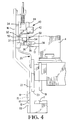
- Fig. 1 is a perspective view of a safety guard system according to the invention in association with a machine ram;
- Fig. 2 is a side elevation view of the safety guard system;
- Fig. 3 is a perspective view of a prior art machine without the safety guard system;
- Fig. 4 is a side elevation view of the ram at the beginning of a ram stroke and the safety guard in an open position;
- Fig. 5 is a side elevation view of the ram partially descended and the safety guard in a closed position;
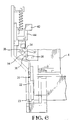
- Fig. 6 is a side elevation view of the ram fully descended after having decoupled from the safety guard;
- Fig. 7 illustrates the ram decoupling from the safety guard when the safety guard meets an obstruction; and
- Figs. 8-10 are schematic representations of a switching and control system during different stages of operation of the safety guard system.
- With reference to Figs. 1 and 2, a safety guard system according to the invention is shown in association with relevant portions of a terminal crimping machine which is operable for deforming a
terminal 2 onto the end of a wire 3, although the safety guard system can be utilized on numerous other machines which have a ram movable through a ram stroke. The terminal crimping machine has apress ram 4 which is mounted for reciprocation with respect to abase 5. Thepress ram 4 is driven downwardly through a ram stroke by an actuator such as an electric motor (not shown) upon generation of an appropriate start signal which is typically initiated through a foot switch controlled by the machine operator. Thepress ram 4 has a slot 6 which receives a knob 7 of a terminal applicator shown generally as 8. Theterminal applicator 8 includes anapplicator ram 9 which carries anupper crimping die 10 which cooperates with a lower crimping die, or anvil, 11 to deform theterminal 2 tightly around the wire 3. Theterminal applicator 8 receives terminals in strip form from a supply and automatically severs an individual terminal from the strip and feeds thesevered terminal 2 to awork zone 12 above theanvil 11 with each cycle of thepress ram 4. A complete description of such aterminal applicator 8 is contained in U.S. Patent No. 3,184,950 which is incorporated by reference as if set forth fully herein. - Safety and noise considerations dictate that the terminal crimping machine be substantially surrounded by an enclosure. The enclosure is preferably made from a clear polycarbonate plastic material. A
section 14 of the enclosure is mounted on a hinge (not shown) to permit pivoting of theenclosure section 14 and thereby provide access to the machine for service during intervals between crimping cycles. An appropriate interlock may be provided to prevent cycling the machine when theenclosure section 14 is open. Awindow 15 defined by a cutout in theenclosure section 14 provides an opening through which the wire 3 may be introduced to thework zone 12 by the machine operator, who then generates the start signal to actuate the ram. - A prior art crimping machine without the safety guard of the present invention is shown in Fig. 3 with an
enclosure section 94 having awindow 95. Safety considerations dictate that thewindow 95 be dimensioned quite narrow to preclude any body part, including a finger, from being inserted into the work zone through the window. Thewindow 95 includes avertical section 96 and ahorizontal slot 97 which extends to anexit 98 at a side edge of the enclosure section. Typically thevertical section 96 has a width of approximately .25 inch (6.35 mm), and the portion of theslot 97 immediately adjacent to the vertical section has a height of similar dimension. Experienced machine operators prefer to hold a group of wires in one hand and to sweep individual wires into the work zone for crimping in quick succession while withdrawing the crimped wires through theexit 98 with the other hand. The configuration and dimensions of thewindow 95 hinder the operator from sweeping the wires through the machine at a rapid pace, thereby slowing production rates. This leads to operator frustration and causes operators to remove or alter the enclosure. - For a machine with the safety guard system of the present invention, the cutout can be significantly larger than would otherwise be acceptable because the safety guard system ensures that a foreign object in the work zone will be sensed and the crimping cycle will be halted before an injury can occur. Referring back to Fig. 1, the
window 15 may now be approximately one inch high fromupper edge 18 tolower edge 19, and approximately four inches wide fromside edge 55 toside edge 57, thus permitting the machine operator to sweep and maneuver the wires through the work zone at a rapid rate, and to withdraw the wires throughpassageway 59 betweensides - With reference to Figs. 1 and 2, the invention comprises a safety guard shown generally as 20 which includes a
shutter section 22 and aslide section 24. Theshutter section 22 is preferably made from a clear plastic material while theslide section 24 is preferably formed from a metal strip material. Theshutter section 22 and theslide section 24 are coupled together such as by threadedfasteners 25 for movement as an integral safety guard unit. Theslide section 24 is guided for vertical movement along a roller bearingslide 16 which is attached to theenclosure section 14. Arod 26 attached at an upper end of theslide section 24 is slidable within a hole in abracket 17 which is fixed to theenclosure section 14. Thesafety guard 20 is biased downwardly by aspring 28 disposed over therod 26 between thebracket 17 and theslide section 24. - A
releasable coupling 30 provides a connection between thesafety guard 20 and thepress ram 4. Thereleasable coupling 30 includes alink 34 having one end that is pivotably mounted on apin 35 which extends between and is held in a pair ofopposed flanges 32 fixed to theslide section 24. The other end of thelink 34 carries apin 36 which is receivable in acutout 38 formed in ablock 13 attached to thepress ram 4. A torsion spring (not shown) is arranged to bias thelink 34 in a counterclockwise direction. Thereleasable coupling 30 enables theram 4 to carry thesafety guard 20 between an open position with respect to the work zone as shown in Figs. 2 and 4, and a closed position with respect to the work zone as shown in Fig. 5. The closed position is set by a stop connected to the roller bearingslide 16 which limits the downward movement of the safety guard. When the safety guard reaches the closed position, the safety guard decouples from the press ram which continues downward through a crimping stroke, as will be more fully described below. - When the
safety guard 20 is in the open position shown in Figs. 2 and 4, abottom edge 23 of theshutter section 22 is disposed level with or relatively higher than theupper edge 18 of thewindow 15, thereby providing access through the full area of thewindow 15 to thework zone 12. When the safety guard is in the closed position shown in Fig. 5, a gap remains between thebottom edge 23 and thelower edge 19 of the window so that a wire that is being crimped is not engaged by thebottom edge 23. - A
guard sensor 40 effects a first signal when thesafety guard 20 reaches the closed position. Theguard sensor 40 may be, for example, a Hall effect switch 42 fixed to theenclosure section 14 which senses the presence or absence in the switch of ametal plate member 44 which is attached to theslide section 14 for movement with thesafety guard 20. For clarity in Figs. 5-7, theswitch 42 and theplate member 44 are illustrated in an orientation which is rotated ninety degrees on a vertical axis from their preferred orientation. Theswitch 42 is coupled in an electrical circuit, shown schematically in Figs. 8-10, between anelectrical power source 72 and acontroller 74 which is operable to terminate the ram stroke. Thecontroller 74 preferably includes a brake and an application and release mechanism such as a solenoid. The brake is normally on, i.e., movement of thepress ram 4 is prevented by the brake unless the solenoid is energized to release the brake, thereby providing a fail safe brake system. The normally closedswitch 42 is tripped open when theplate member 44 is in the switch, which situation exists throughout the range of movement of thesafety guard 20 from the open position shown in Fig. 4 to nearly the closed position shown in Fig. 5. When thesafety guard 20 reaches the closed position shown in Fig. 5, theswitch 42 closes as theplate member 44 exits the switch, thereby effecting the first signal which energizes the controller to release the brake. - An
object sensor 50 effects a second signal when thesafety guard 20 decouples from thepress ram 4. Theobject sensor 50 may be acontact switch 52 having atrigger 54 which is engaged by apad 37 attached to thelink 34 when the link is in a horizontal position. Theswitch 52 is normally open and is wired parallel to theswitch 42 in the circuit for the controller. Theswitch 52 is closed whenever the safety guard is coupled to the press ram due to thepad 37 engaging thetrigger 54, thereby energizing the controller so as to maintain the brake released when the safety guard is in the open position prior to initiation of a ram stroke. This state is shown schematically in Fig. 8. During a ram stroke, the safety guard is driven to the closed position shown in Fig. 5, and theswitch 42 closes. Continued downward movement of thepress ram 4 causes pivoting of thelink 34 which disengages thepad 37 fromtrigger 54, as shown in Fig. 6, thereby opening theswitch 52 and effecting the second signal. The state of theswitches source 72, and this would normally deenergize thecontroller 74 and permit the brake to apply. However, since the safety guard has already reached the closed position, theswitch 42 has effected the first signal which energizes the controller and maintains the brake released. Once the safety guard reaches the closed position, completion of the ram stroke is enabled by the first signal regardless of the second signal. - Fig. 7 illustrates what happens when a finger or other obstruction is inserted into the work zone during a ram stroke. As the
safety guard 20 is driven down by theram 4, thebottom edge 23 of theshutter section 22 engages the obstruction before the safety guard reaches the fully closed position. Due to thereleasable coupling 30, the safety guard decouples from the ram without inflicting any injury to the body part. During the decoupling, thelink 34 is pivoted clockwise, thereby disengaging thetrigger 54 so as to effect the second signal. Since the safety guard has not reached the closed position, theplate member 44 is in theswitch 42, and the first signal has not been effected. This state is shown schematically in Fig. 10. Upon receiving the second signal prior to receiving the first signal, thecontroller 74 is deenergized and the brake is applied, thereby terminating the ram stroke and stopping the ram before serious injury is inflicted on the body part. - The invention provides a safety guard system that permits increased access to the work zone of a machine during time periods when the machine ram is remote from the work zone. The system includes a movable safety guard that closes during a stroke of the ram toward the work zone, and a control system which is operable to terminate the ram stroke if the safety guard is held open by an obstruction.
Claims (7)
- A safety guard system (20) for a machine having a ram (4) movable toward and away from a work zone, and an actuator operable for driving the ram through a ram stroke toward the work zone, the safety guard system (20) characterized bya safety guard (20) mounted for movement along a guard path between open and closed positions with respect to the work zone, the safety guard (20) being releasably coupled (30) to the ram for movement during the ram stroke from the open to the closed position before completion of the ram stroke, the safety guard (20) being arranged to decouple from the ram upon either one of reaching the closed position or earlier encountering an obstruction in the guard path;a guard sensor (40) which effects a first signal upon the safety guard (20) reaching the closed position;an object sensor (50) which effects a second signal upon decoupling of the safety guard from the ram; and,a controller (74) responsive to the first and second signals such that the controller (74) enables completion of the ram stroke upon receiving the first signal, and the controller (74) terminates the ram stroke upon receiving the second signal prior to receiving the first signal.
- The safety guard system according to claim 1, characterized in that the safety guard (20) is coupled to the ram by a pivotable link (34).
- The safety guard system according to claim 2, characterized in that the pivotable link (34) has one end pivotally attached (35) to the safety guard (20) and an other end (36) which is arranged to nest in a cutout (38) formed in the ram (4) such that the link (34) will pivot and the other end will ride out of the cutout to effect the decoupling.
- The safety guard system according to claim 3, characterized in that the object sensor (50) is a switch (52) which is actuated by pivoting of the link (34).
- The safety guard system according to claim 1, characterized in that the controller (74) includes a brake which is operable to stop the ram (4).
- The safety guard system according to claim 5, characterized in that the brake is normally applied so as to prevent movement of the ram (4), and further characterized by a source of power and means for transmitting the power to the brake, the power being effective to release the brake and enable movement of the ram.
- The safety guard system according to claim 6, characterized in that the means for transmitting includes the guard sensor (40) and the object sensor (50) coupled in respective parallel branches of a power transmission network, the guard sensor (50) being effective to interrupt the power to the brake through one of the branches unless the safety guard is in the closed position, and the object sensor (50) being effective to interrupt the power to the brake through the other of the branches upon decoupling of the safety guard from the ram.
Applications Claiming Priority (2)
| Application Number | Priority Date | Filing Date | Title |
|---|---|---|---|
| US414476 | 1995-03-31 | ||
| US08/414,476 US5560466A (en) | 1995-03-31 | 1995-03-31 | Safety guard system for machine having a ram |
Publications (1)
| Publication Number | Publication Date |
|---|---|
| EP0735308A1 true EP0735308A1 (en) | 1996-10-02 |
Family
ID=23641619
Family Applications (1)
| Application Number | Title | Priority Date | Filing Date |
|---|---|---|---|
| EP96302143A Ceased EP0735308A1 (en) | 1995-03-31 | 1996-03-28 | Safety guard system for machine having a ram |
Country Status (2)
| Country | Link |
|---|---|
| US (1) | US5560466A (en) |
| EP (1) | EP0735308A1 (en) |
Cited By (1)
| Publication number | Priority date | Publication date | Assignee | Title |
|---|---|---|---|---|
| EP2698885A1 (en) | 2012-08-15 | 2014-02-19 | Wezag GmbH Werkzeugfabrik | Change adapter for a crimping machine |
Families Citing this family (5)
| Publication number | Priority date | Publication date | Assignee | Title |
|---|---|---|---|---|
| DE19642204C2 (en) * | 1996-10-12 | 1999-07-22 | Telegaertner Geraetebau Gmbh | Safety device on metal forming machines |
| US6389875B1 (en) * | 1998-10-02 | 2002-05-21 | Ralph L. Barnett | Zero speed indicating devices and process of testing same |
| US6276052B1 (en) * | 1999-08-26 | 2001-08-21 | The Whitaker Corporation | Applicator seating sensor |
| US7299855B2 (en) * | 2004-07-08 | 2007-11-27 | L&P Property Management Company | Die casting reciprocator safety bar |
| DE102023102890B4 (en) * | 2023-02-07 | 2026-03-05 | Multivac Sepp Haggenmüller Se & Co. Kg | Protective slide for a work machine |
Citations (9)
| Publication number | Priority date | Publication date | Assignee | Title |
|---|---|---|---|---|
| DE852204C (en) * | 1951-04-24 | 1952-10-13 | Baroper Federnfabrik Schulte & | Securing to prevent accidents on processing machines, z. B. Foot kick presses or the like. |
| DE949919C (en) * | 1952-04-19 | 1956-09-27 | Jagenberg Werke Ag | Finger protection device for pressing, punching or the like. |
| US3184950A (en) * | 1961-10-02 | 1965-05-25 | Amp Inc | Connector feeding device |
| US4060160A (en) * | 1975-11-17 | 1977-11-29 | Raymond Stanley Lieber | Safety guard for power operated machine |
| GB1601452A (en) * | 1978-05-19 | 1981-10-28 | Wickman Mach Tool Mfg | Guards |
| US4586248A (en) * | 1984-09-20 | 1986-05-06 | Ho Kwang Liang | Safety device for arbor of fastening machine |
| EP0252998A1 (en) * | 1986-07-05 | 1988-01-20 | Schaeffer GmbH | Machine for the attachment of rivets, snap fasteners or the like |
| DE3819090A1 (en) * | 1988-06-04 | 1989-12-07 | Schaeffer Gmbh | Machine for placing rivets, pressure heads or the like |
| WO1993012680A1 (en) * | 1992-01-03 | 1993-07-08 | Schaeffer Gmbh | Machine for fitting rivets, press-studs or the like |
Family Cites Families (8)
| Publication number | Priority date | Publication date | Assignee | Title |
|---|---|---|---|---|
| US3186256A (en) * | 1963-07-22 | 1965-06-01 | Reznick Louis | Safety guards for brakes, punch presses and similar machines |
| US3487182A (en) * | 1969-02-06 | 1969-12-30 | Positive Safety Mfg Co The | Safety mechanism for power-operated presses and the like |
| US3939314A (en) * | 1974-06-24 | 1976-02-17 | The Positive Safety Manufacturing Company | Safety device for power-operated presses and the like |
| JPS5158157A (en) * | 1974-11-15 | 1976-05-21 | Yoshida Kogyo Kk | Suraidofuasunaano tomegutoritsukeki niokeru tomegutoritsukepanchinosadoseigyohohotosono sochi |
| DE2556516C2 (en) * | 1975-12-16 | 1985-03-28 | William Prym-Werke Kg, 5190 Stolberg | Working machine with an upper tool that can be moved towards a lower tool |
| US4527684A (en) * | 1982-12-20 | 1985-07-09 | Fort Wayne Truck Parts & Equipment, Inc. | Ram supported sensing shield for power presses |
| SE464760B (en) * | 1983-06-10 | 1991-06-10 | Hymo Ab | SAFETY DEVICE MUST STOP MOVING WITH A LIFT TABLE, AN ELEVATOR, INDUSTRIAL PORT OR LIKE |
| JPH0232650Y2 (en) * | 1985-07-10 | 1990-09-04 |
-
1995
- 1995-03-31 US US08/414,476 patent/US5560466A/en not_active Expired - Lifetime
-
1996
- 1996-03-28 EP EP96302143A patent/EP0735308A1/en not_active Ceased
Patent Citations (9)
| Publication number | Priority date | Publication date | Assignee | Title |
|---|---|---|---|---|
| DE852204C (en) * | 1951-04-24 | 1952-10-13 | Baroper Federnfabrik Schulte & | Securing to prevent accidents on processing machines, z. B. Foot kick presses or the like. |
| DE949919C (en) * | 1952-04-19 | 1956-09-27 | Jagenberg Werke Ag | Finger protection device for pressing, punching or the like. |
| US3184950A (en) * | 1961-10-02 | 1965-05-25 | Amp Inc | Connector feeding device |
| US4060160A (en) * | 1975-11-17 | 1977-11-29 | Raymond Stanley Lieber | Safety guard for power operated machine |
| GB1601452A (en) * | 1978-05-19 | 1981-10-28 | Wickman Mach Tool Mfg | Guards |
| US4586248A (en) * | 1984-09-20 | 1986-05-06 | Ho Kwang Liang | Safety device for arbor of fastening machine |
| EP0252998A1 (en) * | 1986-07-05 | 1988-01-20 | Schaeffer GmbH | Machine for the attachment of rivets, snap fasteners or the like |
| DE3819090A1 (en) * | 1988-06-04 | 1989-12-07 | Schaeffer Gmbh | Machine for placing rivets, pressure heads or the like |
| WO1993012680A1 (en) * | 1992-01-03 | 1993-07-08 | Schaeffer Gmbh | Machine for fitting rivets, press-studs or the like |
Cited By (2)
| Publication number | Priority date | Publication date | Assignee | Title |
|---|---|---|---|---|
| EP2698885A1 (en) | 2012-08-15 | 2014-02-19 | Wezag GmbH Werkzeugfabrik | Change adapter for a crimping machine |
| US10862258B2 (en) | 2012-08-15 | 2020-12-08 | Wezag Gmbh Werkzeugfabrik | Set of interchangeable crimp units |
Also Published As
| Publication number | Publication date |
|---|---|
| US5560466A (en) | 1996-10-01 |
Similar Documents
| Publication | Publication Date | Title |
|---|---|---|
| AU667057B2 (en) | Brake press safety apparatus | |
| JP3817272B2 (en) | Banding machine having primary and secondary tension units and control system therefor | |
| US6752253B2 (en) | Guard means for machines, more particularly pressbrakes, guillotines, stamping machines and the like | |
| US5560466A (en) | Safety guard system for machine having a ram | |
| US6119749A (en) | Taping device | |
| US4457195A (en) | Automatic strip cutting machine | |
| CA2219989A1 (en) | Device for fitting rivets or control therefor | |
| CN112628998A (en) | Air conditioner with hand clamping prevention function and control method thereof | |
| EP0952278B1 (en) | Reinforcing bars binding machine with safety device | |
| US4956938A (en) | Safety device for power operated overhead door | |
| KR20230153938A (en) | Electrical terminal crimp applicator system | |
| EP0001891B1 (en) | Apparatus for inserting wires into electrical terminals | |
| EP0787453B1 (en) | Device for the closing and automatic opening of the cover of a cooking instrument, especially grills, griddles and the like | |
| US6470941B1 (en) | Method and device for welding strips of a thermoplastic material | |
| CA3077992A1 (en) | Deforming machine | |
| EP0598235B1 (en) | Automatic vending machine and door switch apparatus | |
| US5007160A (en) | Apparatus for press-installing wires | |
| EP1522784A1 (en) | Device with safety system | |
| EP0995941B1 (en) | Component mounting machine and safety device thereof | |
| EP2106490A1 (en) | Improved apparatus for electronic-control automatic powering of sliding gates | |
| JP3671083B2 (en) | Check method of punch following machine | |
| EP0977228A2 (en) | Key-controlled electromechanical safety switch with electromagnetic controlled blocking device | |
| JPH08277999A (en) | Safety guard system for machines with ram | |
| CA2268449A1 (en) | Safety device on metal-forming machine tools | |
| US5579685A (en) | Breakaway engagement mechanism |
Legal Events
| Date | Code | Title | Description |
|---|---|---|---|
| PUAI | Public reference made under article 153(3) epc to a published international application that has entered the european phase |
Free format text: ORIGINAL CODE: 0009012 |
|
| AK | Designated contracting states |
Kind code of ref document: A1 Designated state(s): DE FR GB IT NL |
|
| 17P | Request for examination filed |
Effective date: 19961122 |
|
| GRAG | Despatch of communication of intention to grant |
Free format text: ORIGINAL CODE: EPIDOS AGRA |
|
| 17Q | First examination report despatched |
Effective date: 19990930 |
|
| STAA | Information on the status of an ep patent application or granted ep patent |
Free format text: STATUS: THE APPLICATION HAS BEEN REFUSED |
|
| 18R | Application refused |
Effective date: 20000402 |