EP0740909A1 - Schischuh - Google Patents
Schischuh Download PDFInfo
- Publication number
- EP0740909A1 EP0740909A1 EP96810082A EP96810082A EP0740909A1 EP 0740909 A1 EP0740909 A1 EP 0740909A1 EP 96810082 A EP96810082 A EP 96810082A EP 96810082 A EP96810082 A EP 96810082A EP 0740909 A1 EP0740909 A1 EP 0740909A1
- Authority
- EP
- European Patent Office
- Prior art keywords
- stop
- ski boot
- arm
- finger
- rod
- Prior art date
- Legal status (The legal status is an assumption and is not a legal conclusion. Google has not performed a legal analysis and makes no representation as to the accuracy of the status listed.)
- Granted
Links
- 239000002184 metal Substances 0.000 claims description 7
- 230000000694 effects Effects 0.000 claims description 6
- 230000006835 compression Effects 0.000 claims description 3
- 238000007906 compression Methods 0.000 claims description 3
- 238000005452 bending Methods 0.000 description 2
- 230000015572 biosynthetic process Effects 0.000 description 1
- 239000000463 material Substances 0.000 description 1
- 239000011435 rock Substances 0.000 description 1
Images


Classifications
-
- A—HUMAN NECESSITIES
- A43—FOOTWEAR
- A43B—CHARACTERISTIC FEATURES OF FOOTWEAR; PARTS OF FOOTWEAR
- A43B5/00—Footwear for sporting purposes
- A43B5/04—Ski or like boots
- A43B5/0427—Ski or like boots characterised by type or construction details
- A43B5/047—Ski or like boots characterised by type or construction details provided with means to improve walking with the skiboot
- A43B5/0474—Ski or like boots characterised by type or construction details provided with means to improve walking with the skiboot having a walk/ski position
Definitions
- the present invention relates to a ski boot consisting of a lower part surrounding the foot and the heel and of a rod-shaped rod articulated on the lower part and provided with at least one closure and tightening loop, and comprising, at the rear, a device for locking the rod in the descent position inclined towards the front, and unlocking means.
- such a shoe is known from document EP-A-0 086 908.
- This shoe comprises, at the rear, a rocker articulated on the upper and cooperating with a fixed stop on the shell of the shoe. Unlocking is carried out by pressing the upper arm of the rocker accessible through a cutout in the rod.
- Such a rocker can itself be equipped with an auxiliary locking device making it possible to keep the rocker in position away from the stop. Such a device is described in document CH-A-678 685.
- a shoe is also known which is equipped with a rocker according to document EP-0 086 908 and with a rotary button actuating a cam acting on the rocker to keep it in the unlocked position.
- rocker with direct actuation requires a cut in the back of the rod, not very aesthetic cut and letting penetrate the snow with the risk of ice formation.
- the rocker actuated by means of a cam constitutes a relatively bulky assembly.
- control of such a rocker by a cable connected to a loop of the collar is not more convenient, as shown in US Patent 5,136,794.
- the aim of the present invention is to produce a less bulky locking device, requiring no cutting at the rear of the rod, and much easier to actuate by a pulling cable connected to a loop of the collar or to any other member. control.
- the shoe according to the invention is characterized in that the locking device consists, on the one hand, of a pawl mounted on the lower part of the shoe around a horizontal axis, having an arm directed approximately vertically towards the high and stressed by an elastic means tending to separate said arm from the shell and, on the other hand, from a stop located on the internal face of the rod and against which the end of the ratchet arm abuts while bending , in the locked position, and in that the unlocking means consist of a finger oriented so as to move the pawl away from the stop when it is actuated.
- the finger advantageously constitutes the first arm of a bent lever articulated on the internal face of the rod and actuated by an actuating member mounted on the external face of the rod.
- a bent lever has the advantage of being able to be actuated easily by a traction cable connected, for example, to a loop of the collar.
- the arms of this bent lever can be relatively short.
- the bent lever advantageously constitutes a single piece with the stop then produced in the form of a tilting stop.
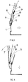
- Figure 1 is a side view of a shoe whose rear part is shown in vertical axial section, according to a first embodiment.
- FIG. 2 is a detailed view of the device for locking the upper of the shoe shown in FIG. 1.
- Figure 3 shows, in section, the rear part in the unlocking phase.
- Figure 4 is a view similar to Figure 2 showing the shoe after unlocking the upper.
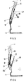
- Figure 5 is a similar view in the on position.
- Figure 6 is a similar view in a position preceding the automatic locking of the collar.
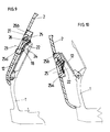
- Figure 7 is a partial view of a second embodiment.
- Figure 8 is a partial view of a third embodiment.
- Figures 9 and 10 show a fourth embodiment.
- the shoe shown in Figure 1 consists essentially of a lower part formed by a shell 1 with variable volume surrounding the foot and the heel and a rod formed by a collar 2 articulated on the shell 1 at two opposite points 3 approximately level of the malleolus.
- the shell 1 is provided with two tightening loops 4 and 5.
- the collar 2 is also provided with two closing and tightening loops 6 and 7.
- the collar 2 carries, on its internal face, a stop 8 pivotally mounted around a horizontal axis 9.
- This stop 8 is in the form of a bent lever of which a first arm 8a is held in abutment against the wall of the collar 2 by a spring in hunting horn surrounding the axis 9 and a second arm 8b, directed towards the front of the shoe and to which is attached the end of a tube 10 in which is housed a slide 30 fixed to the end of a cable 11, the other end of which is connected to the loop 6 of the collar in such a way that the opening of the loop 6 exerts traction on the cable 11.
- a spring 31 working in compression between the slide 30 and the bottom of the tube 10.
- This spring has the function of absorbing the difference in travel between the cable 11 and the arm 8b of the stop 8.
- FIG. 1 we have schematically represented the axis of articulation 14 of the tensioning lever 15 of the loop 6 on the collie r 2 and the articulation axis 16 of the tie rod 17 of this loop on the tensioning lever 15.
- the cable 11 is here attached to the axis 16, as shown diagrammatically.
- the same type of loop is fitted to the ROSSIGNOL MID MATIC models.
- the cable has been shown connected to the upper loop 6, it is advantageous to connect it to the lower loop 7, because the opening of the loop 7 has the effect of releasing the instep and thus facilitating walking.
- the stop 8 has a substantially horizontal lower face 8c in the locked position and constituting the stop face itself.
- This face 8c which connects the two arms 8a and 8b is limited, on the arm 8a, by a lug 8d.
- On the hull is mounted a pawl 12 articulated around a horizontal axis 13 and held in a substantially vertical position by a spring in hunting horn mounted around the axis 13.
- Figure 1 shows the shoe in the closed closed position ready for the descent.
- the collar 2 is locked in the lowering position by the pawl 12, the arm of which abuts approximately perpendicularly against the lower face 8c of the stop 8.
- the pawl 12 is here also in lateral abutment against the lug 8d of the stop.
- the spring 31 is slightly compressed, the force which it exerts is in all cases less than the sum of the force of the return spring in the hunting horn of the stop 8 and the force of the return spring of the pawl 12.
- the opening of the loop 6 has the effect of exerting a traction on the cable 11 which compresses the spring 31 by the slide 30.
- the tube 10 is driven to its turn and exerts traction on the arm 8b of the stop 8, which has the effect of tilting this stop.
- the lug 8d spreads and rotates the pawl 12, as shown in FIG. 2. In this position, the pawl is in lateral support on the end of the lug 8d.
- the loop 6 and therefore the cable 11 can continue its race until the spring 31 is fully compressed.
- FIG. 6 shows the locking device just before the automatic re-locking of the collar 2 on the shell 1.
- the loop 6 is closed and the tension of the cable 11 on the spring 31 is released.
- the collar 2 is still in the upright position.
- the collar 2 rocks in the direction of the arrow and when the axis 9 of the stop 8 exceeds the end of the pawl 12, the stop 8 returns to the position shown in Figure 1 under l effect of its return spring and the pawl 12 again arches on the face 8c of the stop 8 by locking the collar 2.
- the cable 11 could be actuated by a particular member such as an auxiliary loop, a rotary button or a pull button mounted on the collar 2.
- the bent lever constituted by the arms 8a and 8b could be a separate part from the stop which would then be a fixed part.
- the tilting stop 8 could be actuated directly, i.e. without going through a cable.
- the arm 8b could be eliminated and the stop, integral with its axis 9, could be actuated by its axis by means of an external member such as a lever or a button placed on the collar at the height of the stop.
- the stop could be dissociated from the unlocking member which would simply consist of an unlocking finger corresponding to the arm 8a. This is why, in general, we can speak of an unlocking finger.
- the springs in hunting horn could be replaced by any other elastic element tending to maintain the tilting stop, respectively the unlocking finger, and the pawl in the position represented in FIG. 1.
- FIG. 7 represents an embodiment in which the pawl 12 cooperates with a stop 18 formed on the collar 2. Unlocking is ensured by a lever 19 mounted around a horizontal axis on the collar 2 and whose lower arm is curved 19a constitutes the unlocking finger making it possible to separate the pawl 12 from the stop 18. A hunting horn spring recalls the lever clockwise. In the on position, the pawl 12 slides on the end 18a of the stop 18.
- the unlocking finger is constituted by the end 20a of a pusher 20 mounted on a spring 21.
- a locking of the pusher 20 by rotation in position pressed could be easily achieved.
- a pawl 12 cooperating with a stop 18 formed on the collar 2.
- the stop 18 is reinforced by a metal part 22 fixed to the collar 2 by two rivets represented by their axes 23, on each side of a cut 24 open at the bottom.
- Unlocking is ensured by a rocker 25 made of plastic material housed without play in a cutout 27 of the collar 2 and articulated around a horizontal axis 26 on the metal part 22 whose fixing rivets are therefore located on each side of the cutout 27
- the lever 25 has two ends in the form of pushers 25a and 25b which can be actuated from the outside of the collar 2.
- the lower pushbutton 25a projects towards the inside of the collar and constitutes the unlocking finger.
- the absence of play between the lever 25 and the cutout 27 ensures, on the one hand, the tightness and, on the other hand, the friction keeping of the lever in the chosen position.
- Pressing the pusher 25a has the effect of spreading the pawl 12 from the metal part 22 and from the stopper 18 and therefore to unlock the collar 2 which can tilt as shown in FIG. 10.
- the rocker 25 is narrower than the cut out 24 in the metal part 22, so that this metal part 22 does not prevent the rocker from turning sufficiently to push back and hold the pawl 12 for sure out of the path of the stop 18.
Landscapes
- Health & Medical Sciences (AREA)
- General Health & Medical Sciences (AREA)
- Physical Education & Sports Medicine (AREA)
- Footwear And Its Accessory, Manufacturing Method And Apparatuses (AREA)
Applications Claiming Priority (2)
| Application Number | Priority Date | Filing Date | Title |
|---|---|---|---|
| CH1272/95 | 1995-05-03 | ||
| CH01272/95A CH690289A5 (fr) | 1995-05-03 | 1995-05-03 | Chaussure de ski. |
Publications (2)
| Publication Number | Publication Date |
|---|---|
| EP0740909A1 true EP0740909A1 (de) | 1996-11-06 |
| EP0740909B1 EP0740909B1 (de) | 1999-06-02 |
Family
ID=4206535
Family Applications (1)
| Application Number | Title | Priority Date | Filing Date |
|---|---|---|---|
| EP19960810082 Expired - Lifetime EP0740909B1 (de) | 1995-05-03 | 1996-02-09 | Schischuh |
Country Status (3)
| Country | Link |
|---|---|
| EP (1) | EP0740909B1 (de) |
| CH (1) | CH690289A5 (de) |
| DE (1) | DE69602677T2 (de) |
Cited By (6)
| Publication number | Priority date | Publication date | Assignee | Title |
|---|---|---|---|---|
| EP1915917A1 (de) * | 2006-10-11 | 2008-04-30 | LISA Lange International Sàrl | Sport shoe with articulated cuff for a walking position |
| EP2486817A1 (de) * | 2011-02-03 | 2012-08-15 | Rossignol Lange S.R.L. | Sportschuh mit angelenktem Schaft für eine Laufstellung |
| ITMO20110069A1 (it) * | 2011-04-01 | 2012-10-02 | Andrea Bazzani | Sistema gancio/leva per scarponi da sci alpinismo a chiusura/apertura perfezionato |
| ITPD20110331A1 (it) * | 2011-10-20 | 2013-04-21 | Garmont S R L | Scarpone da sci con meccanismo migliorato della selezione sciata-camminata |
| ITTV20130198A1 (it) * | 2013-11-29 | 2015-05-30 | Scarpa Calzaturificio Spa | Scarpone da sci |
| US9241532B2 (en) | 2012-01-04 | 2016-01-26 | K-2 Corporation | Ski/walk mechanism |
Citations (4)
| Publication number | Priority date | Publication date | Assignee | Title |
|---|---|---|---|---|
| US5136794A (en) * | 1990-04-24 | 1992-08-11 | Lange International S.A. | Ski boot |
| EP0521282A1 (de) * | 1991-07-01 | 1993-01-07 | Salomon S.A. | Skischuh mit Schwenksperre für den Schaft |
| WO1993012683A1 (de) * | 1991-12-20 | 1993-07-08 | Koflach Sport Gesellschaft Mbh & Co. Kg. | Skischuh |
| EP0577926A1 (de) * | 1992-06-22 | 1994-01-12 | Salomon S.A. | Vorrichtung zum Schliessen eines Schischuhs |
-
1995
- 1995-05-03 CH CH01272/95A patent/CH690289A5/fr not_active IP Right Cessation
-
1996
- 1996-02-09 EP EP19960810082 patent/EP0740909B1/de not_active Expired - Lifetime
- 1996-02-09 DE DE1996602677 patent/DE69602677T2/de not_active Expired - Fee Related
Patent Citations (4)
| Publication number | Priority date | Publication date | Assignee | Title |
|---|---|---|---|---|
| US5136794A (en) * | 1990-04-24 | 1992-08-11 | Lange International S.A. | Ski boot |
| EP0521282A1 (de) * | 1991-07-01 | 1993-01-07 | Salomon S.A. | Skischuh mit Schwenksperre für den Schaft |
| WO1993012683A1 (de) * | 1991-12-20 | 1993-07-08 | Koflach Sport Gesellschaft Mbh & Co. Kg. | Skischuh |
| EP0577926A1 (de) * | 1992-06-22 | 1994-01-12 | Salomon S.A. | Vorrichtung zum Schliessen eines Schischuhs |
Cited By (9)
| Publication number | Priority date | Publication date | Assignee | Title |
|---|---|---|---|---|
| EP1915917A1 (de) * | 2006-10-11 | 2008-04-30 | LISA Lange International Sàrl | Sport shoe with articulated cuff for a walking position |
| US7963050B2 (en) | 2006-10-11 | 2011-06-21 | Lisa Lange International Sarl | Sports boot with articulated upper cuff to provide a position for walking |
| EP2486817A1 (de) * | 2011-02-03 | 2012-08-15 | Rossignol Lange S.R.L. | Sportschuh mit angelenktem Schaft für eine Laufstellung |
| US9770063B2 (en) | 2011-02-03 | 2017-09-26 | Rossignol Lange S.R.L. | Sports boot with a collar articulated for a walking position |
| ITMO20110069A1 (it) * | 2011-04-01 | 2012-10-02 | Andrea Bazzani | Sistema gancio/leva per scarponi da sci alpinismo a chiusura/apertura perfezionato |
| ITPD20110331A1 (it) * | 2011-10-20 | 2013-04-21 | Garmont S R L | Scarpone da sci con meccanismo migliorato della selezione sciata-camminata |
| US9380826B2 (en) | 2011-10-20 | 2016-07-05 | Scott Sports S.A. | Ski boot with improved mechanism to pass from a skiing configuration to a walking configuration |
| US9241532B2 (en) | 2012-01-04 | 2016-01-26 | K-2 Corporation | Ski/walk mechanism |
| ITTV20130198A1 (it) * | 2013-11-29 | 2015-05-30 | Scarpa Calzaturificio Spa | Scarpone da sci |
Also Published As
| Publication number | Publication date |
|---|---|
| EP0740909B1 (de) | 1999-06-02 |
| DE69602677D1 (de) | 1999-07-08 |
| DE69602677T2 (de) | 1999-12-09 |
| CH690289A5 (fr) | 2000-07-14 |
Similar Documents
| Publication | Publication Date | Title |
|---|---|---|
| FR2661076A1 (fr) | Chaussure de ski a tige articulee avec position verrouillee de descente et position liberee de repos ou de marche. | |
| FR2656989A1 (fr) | Chaussure de ski alpin du type a "entree arriere". | |
| EP0097382A1 (de) | Schliessvorrichtung für Sportschuhe | |
| CH657025A5 (fr) | Chaussure de ski munie d'un dispositif de fermeture. | |
| EP0375604B1 (de) | Schischuh | |
| WO2017140767A1 (fr) | Element de maintien d'une chaussure de ski avec une pedale de chaussage pouvant basculer par rapport a l'agrippe talon | |
| EP3437703B1 (de) | Bremsvorrichtung für tourenski | |
| EP0740909B1 (de) | Schischuh | |
| EP0689777B1 (de) | Schischuh | |
| EP1106218A1 (de) | Langlaufski | |
| EP0470383B1 (de) | Skischuh | |
| EP3827887B1 (de) | Hinterbacken für tourenskier | |
| CH686162A5 (fr) | Chaussure de ski. | |
| EP0617902B1 (de) | Skischuh | |
| FR2619999A1 (fr) | Chaussure de ski alpin a tige articulee sur un bas de coque | |
| EP0391813B1 (de) | Schischuh mit hinterem Einstieg | |
| EP0598680B1 (de) | Schischuh | |
| CH680557A5 (de) | ||
| CH689630A5 (fr) | Chaussure de ski en matière synthétique. | |
| EP0761114B1 (de) | Skischuh | |
| FR2708429A1 (fr) | Dispositif de fermeture d'une tige de chaussure de ski. | |
| FR3072884A1 (fr) | Butee de dispositif de fixation d'une chaussure | |
| EP0429373A1 (de) | Skischuh aus Kunststoff | |
| FR2688982A1 (fr) | Dispositif de fermeture de la tige d'une chaussure de ski. | |
| FR2657506A1 (fr) | Chaussure de ski alpin a entree arriere. |
Legal Events
| Date | Code | Title | Description |
|---|---|---|---|
| PUAI | Public reference made under article 153(3) epc to a published international application that has entered the european phase |
Free format text: ORIGINAL CODE: 0009012 |
|
| AK | Designated contracting states |
Kind code of ref document: A1 Designated state(s): DE FR IT |
|
| 17P | Request for examination filed |
Effective date: 19961126 |
|
| GRAG | Despatch of communication of intention to grant |
Free format text: ORIGINAL CODE: EPIDOS AGRA |
|
| 17Q | First examination report despatched |
Effective date: 19980810 |
|
| GRAG | Despatch of communication of intention to grant |
Free format text: ORIGINAL CODE: EPIDOS AGRA |
|
| GRAH | Despatch of communication of intention to grant a patent |
Free format text: ORIGINAL CODE: EPIDOS IGRA |
|
| GRAH | Despatch of communication of intention to grant a patent |
Free format text: ORIGINAL CODE: EPIDOS IGRA |
|
| GRAA | (expected) grant |
Free format text: ORIGINAL CODE: 0009210 |
|
| RAP1 | Party data changed (applicant data changed or rights of an application transferred) |
Owner name: LANGE INTERNATIONAL S.A. |
|
| AK | Designated contracting states |
Kind code of ref document: B1 Designated state(s): DE FR IT |
|
| REF | Corresponds to: |
Ref document number: 69602677 Country of ref document: DE Date of ref document: 19990708 |
|
| ITF | It: translation for a ep patent filed | ||
| PLBE | No opposition filed within time limit |
Free format text: ORIGINAL CODE: 0009261 |
|
| STAA | Information on the status of an ep patent application or granted ep patent |
Free format text: STATUS: NO OPPOSITION FILED WITHIN TIME LIMIT |
|
| 26N | No opposition filed | ||
| PGFP | Annual fee paid to national office [announced via postgrant information from national office to epo] |
Ref country code: IT Payment date: 20080227 Year of fee payment: 13 |
|
| PGFP | Annual fee paid to national office [announced via postgrant information from national office to epo] |
Ref country code: DE Payment date: 20090226 Year of fee payment: 14 |
|
| PGFP | Annual fee paid to national office [announced via postgrant information from national office to epo] |
Ref country code: FR Payment date: 20090225 Year of fee payment: 14 |
|
| REG | Reference to a national code |
Ref country code: FR Ref legal event code: ST Effective date: 20101029 |
|
| PG25 | Lapsed in a contracting state [announced via postgrant information from national office to epo] |
Ref country code: FR Free format text: LAPSE BECAUSE OF NON-PAYMENT OF DUE FEES Effective date: 20100301 |
|
| PG25 | Lapsed in a contracting state [announced via postgrant information from national office to epo] |
Ref country code: DE Free format text: LAPSE BECAUSE OF NON-PAYMENT OF DUE FEES Effective date: 20100901 |
|
| PG25 | Lapsed in a contracting state [announced via postgrant information from national office to epo] |
Ref country code: IT Free format text: LAPSE BECAUSE OF NON-PAYMENT OF DUE FEES Effective date: 20090209 |