EP0740974A2 - Apparatus particularly for preparing the outer surface of the end region of tubes made of plastics - Google Patents
Apparatus particularly for preparing the outer surface of the end region of tubes made of plastics Download PDFInfo
- Publication number
- EP0740974A2 EP0740974A2 EP96106930A EP96106930A EP0740974A2 EP 0740974 A2 EP0740974 A2 EP 0740974A2 EP 96106930 A EP96106930 A EP 96106930A EP 96106930 A EP96106930 A EP 96106930A EP 0740974 A2 EP0740974 A2 EP 0740974A2
- Authority
- EP
- European Patent Office
- Prior art keywords
- shaped
- pivot
- tube
- fixed
- tool
- Prior art date
- Legal status (The legal status is an assumption and is not a legal conclusion. Google has not performed a legal analysis and makes no representation as to the accuracy of the status listed.)
- Granted
Links
Images

Classifications
-
- B—PERFORMING OPERATIONS; TRANSPORTING
- B23—MACHINE TOOLS; METAL-WORKING NOT OTHERWISE PROVIDED FOR
- B23B—TURNING; BORING
- B23B5/00—Turning-machines or devices specially adapted for particular work; Accessories specially adapted therefor
- B23B5/16—Turning-machines or devices specially adapted for particular work; Accessories specially adapted therefor for bevelling, chamfering, or deburring the ends of bars or tubes
- B23B5/161—Devices attached to the workpiece
- B23B5/162—Devices attached to the workpiece with an internal clamping device
-
- B—PERFORMING OPERATIONS; TRANSPORTING
- B29—WORKING OF PLASTICS; WORKING OF SUBSTANCES IN A PLASTIC STATE IN GENERAL
- B29C—SHAPING OR JOINING OF PLASTICS; SHAPING OF MATERIAL IN A PLASTIC STATE, NOT OTHERWISE PROVIDED FOR; AFTER-TREATMENT OF THE SHAPED PRODUCTS, e.g. REPAIRING
- B29C66/00—General aspects of processes or apparatus for joining preformed parts
- B29C66/01—General aspects dealing with the joint area or with the area to be joined
- B29C66/02—Preparation of the material, in the area to be joined, prior to joining or welding
- B29C66/022—Mechanical pre-treatments, e.g. reshaping
- B29C66/0224—Mechanical pre-treatments, e.g. reshaping with removal of material
-
- B—PERFORMING OPERATIONS; TRANSPORTING
- B29—WORKING OF PLASTICS; WORKING OF SUBSTANCES IN A PLASTIC STATE IN GENERAL
- B29C—SHAPING OR JOINING OF PLASTICS; SHAPING OF MATERIAL IN A PLASTIC STATE, NOT OTHERWISE PROVIDED FOR; AFTER-TREATMENT OF THE SHAPED PRODUCTS, e.g. REPAIRING
- B29C65/00—Joining or sealing of preformed parts, e.g. welding of plastics materials; Apparatus therefor
- B29C65/02—Joining or sealing of preformed parts, e.g. welding of plastics materials; Apparatus therefor by heating, with or without pressure
- B29C65/34—Joining or sealing of preformed parts, e.g. welding of plastics materials; Apparatus therefor by heating, with or without pressure using heated elements which remain in the joint, e.g. "verlorenes Schweisselement"
-
- B—PERFORMING OPERATIONS; TRANSPORTING
- B29—WORKING OF PLASTICS; WORKING OF SUBSTANCES IN A PLASTIC STATE IN GENERAL
- B29C—SHAPING OR JOINING OF PLASTICS; SHAPING OF MATERIAL IN A PLASTIC STATE, NOT OTHERWISE PROVIDED FOR; AFTER-TREATMENT OF THE SHAPED PRODUCTS, e.g. REPAIRING
- B29C66/00—General aspects of processes or apparatus for joining preformed parts
- B29C66/50—General aspects of joining tubular articles; General aspects of joining long products, i.e. bars or profiled elements; General aspects of joining single elements to tubular articles, hollow articles or bars; General aspects of joining several hollow-preforms to form hollow or tubular articles
- B29C66/51—Joining tubular articles, profiled elements or bars; Joining single elements to tubular articles, hollow articles or bars; Joining several hollow-preforms to form hollow or tubular articles
- B29C66/52—Joining tubular articles, bars or profiled elements
- B29C66/522—Joining tubular articles
- B29C66/5221—Joining tubular articles for forming coaxial connections, i.e. the tubular articles to be joined forming a zero angle relative to each other
-
- B—PERFORMING OPERATIONS; TRANSPORTING
- B29—WORKING OF PLASTICS; WORKING OF SUBSTANCES IN A PLASTIC STATE IN GENERAL
- B29C—SHAPING OR JOINING OF PLASTICS; SHAPING OF MATERIAL IN A PLASTIC STATE, NOT OTHERWISE PROVIDED FOR; AFTER-TREATMENT OF THE SHAPED PRODUCTS, e.g. REPAIRING
- B29C66/00—General aspects of processes or apparatus for joining preformed parts
- B29C66/50—General aspects of joining tubular articles; General aspects of joining long products, i.e. bars or profiled elements; General aspects of joining single elements to tubular articles, hollow articles or bars; General aspects of joining several hollow-preforms to form hollow or tubular articles
- B29C66/51—Joining tubular articles, profiled elements or bars; Joining single elements to tubular articles, hollow articles or bars; Joining several hollow-preforms to form hollow or tubular articles
- B29C66/52—Joining tubular articles, bars or profiled elements
- B29C66/522—Joining tubular articles
- B29C66/5229—Joining tubular articles involving the use of a socket
-
- B—PERFORMING OPERATIONS; TRANSPORTING
- B29—WORKING OF PLASTICS; WORKING OF SUBSTANCES IN A PLASTIC STATE IN GENERAL
- B29C—SHAPING OR JOINING OF PLASTICS; SHAPING OF MATERIAL IN A PLASTIC STATE, NOT OTHERWISE PROVIDED FOR; AFTER-TREATMENT OF THE SHAPED PRODUCTS, e.g. REPAIRING
- B29C66/00—General aspects of processes or apparatus for joining preformed parts
- B29C66/70—General aspects of processes or apparatus for joining preformed parts characterised by the composition, physical properties or the structure of the material of the parts to be joined; Joining with non-plastics material
- B29C66/73—General aspects of processes or apparatus for joining preformed parts characterised by the composition, physical properties or the structure of the material of the parts to be joined; Joining with non-plastics material characterised by the intensive physical properties of the material of the parts to be joined, by the optical properties of the material of the parts to be joined, by the extensive physical properties of the parts to be joined, by the state of the material of the parts to be joined or by the material of the parts to be joined being a thermoplastic or a thermoset
- B29C66/737—General aspects of processes or apparatus for joining preformed parts characterised by the composition, physical properties or the structure of the material of the parts to be joined; Joining with non-plastics material characterised by the intensive physical properties of the material of the parts to be joined, by the optical properties of the material of the parts to be joined, by the extensive physical properties of the parts to be joined, by the state of the material of the parts to be joined or by the material of the parts to be joined being a thermoplastic or a thermoset characterised by the state of the material of the parts to be joined
- B29C66/7373—Joining soiled or oxidised materials
Definitions
- the present invention relates to an apparatus particularly but not exclusively for preparing the outer surface of the end region of tubes made of plastics.
- These connecting devices are substantially constituted by a collar that surrounds the end regions of two mutually aligned thermoplastic tubes.
- An electric resistor is inserted in the inner part of the connecting device.
- the cleaning of the ends relates both to the elimination of mud, moisture, and sand and to the removal of the thin layer of oxide that unavoidably forms on the outer surface of tubes made of plastics.
- the aim of the present invention is to provide an apparatus that solves the above mentioned drawbacks shown by conventional devices.
- an object of the present invention is to provide an apparatus that combines considerable constructive simplicity with an equally considerable ability to slide and speed in preparing the outer surface of the tubes.
- Another object of the present invention is to provide an apparatus that can be assembled quickly at the end of a tube, minimizing the preparation and adjustment times.
- Another object of the present invention is to provide an apparatus whose operation does not require specialized personnel.
- Another object of the present invention is to provide an apparatus whose treatment quality is competitive with that of the conventional ones and which can be produced with conventional technologies and with costs that are competitive with respect to those of conventional devices.
- an apparatus particularly for preparing the outer surface of the end region of tubes made of plastics, which comprises anchoring means that are fixed, in the operating configuration, to the end region of a tube, a threaded pivot being movably coupled to said anchoring means so that it can rotate and perform a longitudinal translatory motion, said threaded pivot being arranged axially with respect to the tube in the operating configuration, supporting means for at least one tool being coupled to said pivot so that they can rotate rigidly, said tool being arrangeable so that it interferes with, and removes material from, the outer surface of the end region of the tube, said apparatus being characterized in that said anchoring means comprise a substantially cylindrical element, which is shaped at one end so as to form a circumferential groove and is shaped at the other end so as to form guides for elements for anchoring to the tube, said supporting means comprising a first telescopic rod-like arm, which is fixed radially at one of its ends to the free end of said threade
- an apparatus particularly for preparing the outer surface of the end region of tubes made of plastics, according to the invention, is generally designated by the reference numeral 10.
- the apparatus 10 comprises anchoring means, generally designated by the reference numeral 11.
- the anchoring means 11 are fixed, in the operating configuration, to the end region of a tube, designated here by the reference numeral 12, and comprise a substantially cylindrical element 13 that is shaped at one end so as to form a circumferential groove 14 that is adjacent to the lateral surface; the other end is shaped so as to form, in this case, four radial guides 15 that are arranged in a cross-like pattern with respect to each other.
- Each one of the radial guides 15 has, at the lateral surfaces that form them, two facing raised portions 16 that also run in a substantially radial direction.
- a corresponding prism-shaped element 17 is furthermore slideably retained within each one of the radial guides 15; in the operating configuration, said prism-shaped element is pushed by actuation means, described hereinafter, against the inside surface of the tube 12.
- each one of the radial guides 15 has an open bottom that is connected to the groove 14, which accommodates a ring 18 that has an annular surface 19, arranged opposite to the radial guides 15, shaped so as to form a set of teeth, whereas the other annular surface 20 is shaped so as to form a spiral-shaped guide, not shown in the figures, that constitutes said actuation means.
- each one of the prism-shaped elements 17 has, at the side that is adjacent to the annular surface 20, raised portions that are inserted in the spiral-shaped guide and force a sliding coupling of the corresponding prism-shaped elements 17 with respect to the ring 18.
- the toothed annular surface 19 meshes with a bevel gear 21 that is rotatably coupled, along a radial direction, to the cylindrical element 13 and is actuated by actuation means, not shown in the figures, that lie outside the apparatus 10.
- the gear 21 continues axially toward the axis of the element 13 with a cylindrical protrusion 22, whose free end is shaped so as to form a circumferential groove 23.
- the cylindrical protrusion 22 fits in a hole 24 formed in the substantially cylindrical central body 25 of the element 13.
- the element 13, at its central body 25, has an axial through hole 29 inside which a threaded pivot 30 is slidingly retained.
- the threaded pivot 30 indeed has a surface that is shaped so as to form a helical groove 31 that has a constant pitch.
- Coupling means are accommodated in a complementarily shaped seat 32 formed in the central body 25 tangentially to the threaded pivot 30 and can be activated and deactivated manually by the operator; their actuation forces the threaded pivot 30 to perform a longitudinal combined rotary and translatory motion along the axial direction.
- Said coupling means are constituted in this case by a pivot 33 that is slidingly accommodated within the seat 32 and is shaped, in an approximately median region, so as to form a cavity 34 with a region 35 that is shaped complementarily to the threaded pivot 30 (thus forming a female thread portion) and couples with it in a preset position of the pivot 33, which has an end 36 that is available for the action of the operator.
- Elastic return means are included in association with the pivot 33 and are constituted, in this case, by a helical spring 37 that has a fixed base within a perforated prism-shaped block 33a that is detachably fixed to the central body 25 at the seat 32.
- the apparatus 10 also comprises support means, generally designated by the reference numeral 38, which are adapted to support, as will be described hereinafter, a tool that can be positioned so as to interfere with, and remove material from, the outside surface of the end region of the tube 12.
- the support means 38 comprise a first telescopic rod-like arm 39 that has a substantially rectangular cross-section and is fixed, along a direction that is radial with respect to the element 13, to the free end of the threaded pivot 30 and can be elongated by means of a ring nut 40 that is arranged at its rigidly coupled end and actuates a per se known extension and retraction device that is arranged inside it.
- the support means 38 also comprise a second rod-like arm 41 that has a substantially rectangular cross-section and has an end 42 that is rigidly coupled to the free end of the first rod-like arm 39.
- end 42 is shaped so as to form two first tabs 43 that are substantially parallel to each other; a block 44 is fixed to their free ends by means of threaded elements 45.
- a knob 46 is fixed to the block 44 and is substantially parallel to the threaded pivot 30; by means of said knob, the user can impart a rotary motion to the first rod-like arm 39.
- the other end of the second rod-like arm 41 is shaped so as to form two second tabs 47, to which tool supporting means, generally designated by the reference numeral 48, are fixed.
- the tool supporting means 48 are arranged substantially along a radial direction with respect to the tube 12.
- the tool supporting means 48 also comprise a body 49 that is fixed to the second tabs 47.
- the body 49 in this case, is prism-shaped with a square cross-section.
- a cylindrical element 50 is slidingly accommodated within a longitudinal through hole 49a formed in the body 49, and a tool 51 is fixed to the end of said cylindrical element that is directed toward the threaded pivot 30 upon assembly.
- the cylindrical element 50 can slide along the body 49 to a limited extent in a direction that is substantially radial with respect to the tube 12, and is kept pushed against said tube by elastic means that are not shown in the figures.
- operation is as follows: the apparatus 10 is placed at one end of the tube 12 whose outside surface must be treated.
- the prism-shaped elements 17 are inserted in the hole of the tube 12, and by means of the action of the gear 21 and accordingly of the ring 18 said prism-shaped elements 17 move outward in a radial direction until they make contact with the inside surface of the tube 12, against which they abut and push, locking the apparatus 10.
- the operator then adjusts, by means of the ring nut 40, the length of the first rod-like arm 39 and therefore ultimately of the tool 51 according to the diameter of the tube 12.
- the rotation of the second rod-like arm 41 is rigidly associated with the rotation of the threaded pivot 30, which by means of the helical groove 31 formed thereon and after engaging the pivot 33 performs a combined rotary and translatory motion, producing the advancement of the first rod-like element 39 and therefore of the treatment.
- the telescopic arm now designated by the reference numeral 139, comprises a sleeve 152 in which a rod-like element 153 can slide; a rack 156 is rigidly coupled thereto, is accommodated in an adapted longitudinal seat 154, and is fixed by means of screws 155.
- a pinion 157 meshes with the rack 156 and is rotatably coupled to a support 158 that is fixed by means of screws, not shown in the figure, to the outside of the sleeve 152, and enters an adapted slot 160 of said sleeve 152.
- the pinion 157 is rigidly coupled to a knob 161 that is coaxial thereto and is associated with a button-operated pawl 162 that includes a contrast spring 163.
- a bridge-like handle 165 is fixed on the sleeve 152 by means of screws 164 on the region of the pinion 157 and of the pawl 162.
- the pawl 162 allows rotations of the pinion 157, performed by means of the knob 161, in a single direction, and consequent longitudinal movements of the rod-like element 153.
- the materials and the dimensions may be any according to the requirements.
Landscapes
- Engineering & Computer Science (AREA)
- Mechanical Engineering (AREA)
- Shaping Of Tube Ends By Bending Or Straightening (AREA)
- Protection Of Pipes Against Damage, Friction, And Corrosion (AREA)
- Lining Or Joining Of Plastics Or The Like (AREA)
- Moulds For Moulding Plastics Or The Like (AREA)
Abstract
Description
- The present invention relates to an apparatus particularly but not exclusively for preparing the outer surface of the end region of tubes made of plastics.
- Connecting devices that join adjacent portions of tubes made of plastics by hot welding are currently widespread.
- These connecting devices are substantially constituted by a collar that surrounds the end regions of two mutually aligned thermoplastic tubes.
- An electric resistor is inserted in the inner part of the connecting device.
- By passing electric current through said resistor, the mutual melting of the end portions of the tubes is achieved.
- Field practice, however, has pointed out that it is necessary to clean the ends of the tube to be welded before applying the connecting device in order to achieve optimum joining.
- The cleaning of the ends relates both to the elimination of mud, moisture, and sand and to the removal of the thin layer of oxide that unavoidably forms on the outer surface of tubes made of plastics.
- The end parts of tubes to be joined are currently mostly cleaned by hand.
- Manual execution, however, entails various drawbacks, among which the fact that the operator must assess arbitrarily the amount of material that he is removing, although this assessment is very difficult to perform on site.
- Furthermore, manual removal of the material is never uniform and can lead to differences in the diameter of the end regions of the tubes to be welded.
- Furthermore, manual removal is time-consuming and ultimately expensive in terms of production times.
- In order to eliminate these drawbacks, a wide variety of devices, adapted to eliminate in a substantially semiautomatic or automatic manner a layer of material and therefore to prepare the end part of the tubes to be welded, has been conceived.
- The devices that are currently in use, despite achieving their task and substantially improving treatment quality and time requirements with respect to manually-performed preparation, have some drawbacks.
- The main drawbacks are first of all a considerable constructive complexity, which often entails external power sources such as electric motors or the like.
- Furthermore, these devices are complicated to install at the end of the tubes, with an expenditure of time for preparation and of specialized labor.
- Furthermore, the ability of the above-described devices to slide along the tube to be prepared is still not fully satisfactory.
- The aim of the present invention is to provide an apparatus that solves the above mentioned drawbacks shown by conventional devices.
- In relation to this aim, an object of the present invention is to provide an apparatus that combines considerable constructive simplicity with an equally considerable ability to slide and speed in preparing the outer surface of the tubes.
- Another object of the present invention is to provide an apparatus that can be assembled quickly at the end of a tube, minimizing the preparation and adjustment times.
- Another object of the present invention is to provide an apparatus whose operation does not require specialized personnel.
- Another object of the present invention is to provide an apparatus whose treatment quality is competitive with that of the conventional ones and which can be produced with conventional technologies and with costs that are competitive with respect to those of conventional devices.
- This aim, these objects, and others which will become apparent hereinafter are achieved by an apparatus, particularly for preparing the outer surface of the end region of tubes made of plastics, which comprises anchoring means that are fixed, in the operating configuration, to the end region of a tube, a threaded pivot being movably coupled to said anchoring means so that it can rotate and perform a longitudinal translatory motion, said threaded pivot being arranged axially with respect to the tube in the operating configuration, supporting means for at least one tool being coupled to said pivot so that they can rotate rigidly, said tool being arrangeable so that it interferes with, and removes material from, the outer surface of the end region of the tube, said apparatus being characterized in that said anchoring means comprise a substantially cylindrical element, which is shaped at one end so as to form a circumferential groove and is shaped at the other end so as to form guides for elements for anchoring to the tube, said supporting means comprising a first telescopic rod-like arm, which is fixed radially at one of its ends to the free end of said threaded pivot, and a second rod-like arm, which is fixed at one of its ends to the free end of said first arm and supports said tool.
- Further characteristics and advantages of the present invention will become apparent from the description of an embodiment thereof, illustrated only by way of non-limitative example in the accompanying drawings, wherein:
- figure 1 is an axonometric view of an apparatus according to the invention;
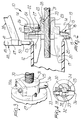
- figure 2 is a partially sectional view, taken along a diametrical plane, of the apparatus according to the invention;
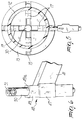
- figure 3 is an axonometric view of a detail of the apparatus according to the invention;
- figure 4 is a partially sectional front view of another detail of the apparatus according to the invention;
- figure 5 is a front orthographic projection view of the apparatus according to the invention;
- figure 6 is an axonometric view of another detail of the apparatus according to the invention;
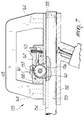
- figure 7 is an enlarged-scale sectional view of a detail of a different embodiment of the telescopic arm included in the apparatus.
- With particular reference to figures 1 to 6, an apparatus, particularly for preparing the outer surface of the end region of tubes made of plastics, according to the invention, is generally designated by the
reference numeral 10. - The
apparatus 10 comprises anchoring means, generally designated by the reference numeral 11. - The anchoring means 11 are fixed, in the operating configuration, to the end region of a tube, designated here by the
reference numeral 12, and comprise a substantiallycylindrical element 13 that is shaped at one end so as to form acircumferential groove 14 that is adjacent to the lateral surface; the other end is shaped so as to form, in this case, fourradial guides 15 that are arranged in a cross-like pattern with respect to each other. - Each one of the
radial guides 15 has, at the lateral surfaces that form them, two facing raisedportions 16 that also run in a substantially radial direction. - A corresponding prism-
shaped element 17 is furthermore slideably retained within each one of theradial guides 15; in the operating configuration, said prism-shaped element is pushed by actuation means, described hereinafter, against the inside surface of thetube 12. - Furthermore, each one of the
radial guides 15 has an open bottom that is connected to thegroove 14, which accommodates aring 18 that has anannular surface 19, arranged opposite to theradial guides 15, shaped so as to form a set of teeth, whereas the otherannular surface 20 is shaped so as to form a spiral-shaped guide, not shown in the figures, that constitutes said actuation means. - More specifically, each one of the prism-
shaped elements 17 has, at the side that is adjacent to theannular surface 20, raised portions that are inserted in the spiral-shaped guide and force a sliding coupling of the corresponding prism-shaped elements 17 with respect to thering 18. - The toothed
annular surface 19 meshes with abevel gear 21 that is rotatably coupled, along a radial direction, to thecylindrical element 13 and is actuated by actuation means, not shown in the figures, that lie outside theapparatus 10. - The
gear 21 continues axially toward the axis of theelement 13 with acylindrical protrusion 22, whose free end is shaped so as to form acircumferential groove 23. - The
cylindrical protrusion 22 fits in ahole 24 formed in the substantially cylindricalcentral body 25 of theelement 13. - The
gear 21, in addition to passing through theelement 13 in a throughhole 26 formed at the lateral surface thereof, is also fixed by means of a threadedelement 27 inserted in athrough hole 28 formed in a direction that is substantially perpendicular to the radial direction in thebody 25; the free end of said threaded element enters thegroove 23. - The
element 13, at itscentral body 25, has an axial throughhole 29 inside which a threadedpivot 30 is slidingly retained. - The threaded
pivot 30 indeed has a surface that is shaped so as to form ahelical groove 31 that has a constant pitch. - Coupling means are accommodated in a complementarily shaped
seat 32 formed in thecentral body 25 tangentially to the threadedpivot 30 and can be activated and deactivated manually by the operator; their actuation forces the threadedpivot 30 to perform a longitudinal combined rotary and translatory motion along the axial direction. - Said coupling means are constituted in this case by a
pivot 33 that is slidingly accommodated within theseat 32 and is shaped, in an approximately median region, so as to form acavity 34 with aregion 35 that is shaped complementarily to the threaded pivot 30 (thus forming a female thread portion) and couples with it in a preset position of thepivot 33, which has anend 36 that is available for the action of the operator. - Elastic return means are included in association with the
pivot 33 and are constituted, in this case, by a helical spring 37 that has a fixed base within a perforated prism-shaped block 33a that is detachably fixed to thecentral body 25 at theseat 32. - The
apparatus 10 also comprises support means, generally designated by thereference numeral 38, which are adapted to support, as will be described hereinafter, a tool that can be positioned so as to interfere with, and remove material from, the outside surface of the end region of thetube 12. - The support means 38 comprise a first telescopic rod-
like arm 39 that has a substantially rectangular cross-section and is fixed, along a direction that is radial with respect to theelement 13, to the free end of the threadedpivot 30 and can be elongated by means of aring nut 40 that is arranged at its rigidly coupled end and actuates a per se known extension and retraction device that is arranged inside it. - The support means 38 also comprise a second rod-
like arm 41 that has a substantially rectangular cross-section and has anend 42 that is rigidly coupled to the free end of the first rod-like arm 39. - More specifically, the
end 42 is shaped so as to form twofirst tabs 43 that are substantially parallel to each other; ablock 44 is fixed to their free ends by means of threadedelements 45. - A
knob 46 is fixed to theblock 44 and is substantially parallel to the threadedpivot 30; by means of said knob, the user can impart a rotary motion to the first rod-like arm 39. - The other end of the second rod-
like arm 41 is shaped so as to form twosecond tabs 47, to which tool supporting means, generally designated by thereference numeral 48, are fixed. - The tool supporting means 48 are arranged substantially along a radial direction with respect to the
tube 12. - The tool supporting means 48 also comprise a
body 49 that is fixed to thesecond tabs 47. - The
body 49, in this case, is prism-shaped with a square cross-section. Acylindrical element 50 is slidingly accommodated within a longitudinal throughhole 49a formed in thebody 49, and atool 51 is fixed to the end of said cylindrical element that is directed toward the threadedpivot 30 upon assembly. - The
cylindrical element 50 can slide along thebody 49 to a limited extent in a direction that is substantially radial with respect to thetube 12, and is kept pushed against said tube by elastic means that are not shown in the figures. - In practice, operation is as follows: the
apparatus 10 is placed at one end of thetube 12 whose outside surface must be treated. - The prism-
shaped elements 17 are inserted in the hole of thetube 12, and by means of the action of thegear 21 and accordingly of thering 18 said prism-shaped elements 17 move outward in a radial direction until they make contact with the inside surface of thetube 12, against which they abut and push, locking theapparatus 10. - The operator then adjusts, by means of the
ring nut 40, the length of the first rod-like arm 39 and therefore ultimately of thetool 51 according to the diameter of thetube 12. - Then the operator, by acting on the
knob 46, turns the second rod-like arm 41, performing the treatment proper. - The rotation of the second rod-
like arm 41 is rigidly associated with the rotation of the threadedpivot 30, which by means of thehelical groove 31 formed thereon and after engaging thepivot 33 performs a combined rotary and translatory motion, producing the advancement of the first rod-like element 39 and therefore of the treatment. - In practice it has been observed that the intended aim and objects have been achieved; in particular, it should be noted that the present invention is constructively simple and can be used quickly and easily by unskilled personnel.
- The extremely easy sliding of the apparatus according to the invention along the tube should also be mentioned.
- Easy applicability to the tube, as well as the safe anchoring of the apparatus according to the invention, should also be noted; its cost, in view of the above-mentioned constructive simplicity, is competitive with respect to conventional devices.
- The present invention is susceptible of numerous modifications and variations, all of which are within the scope of the inventive concept.
- Thus, for example, with particular reference to figure 7, in a possible further embodiment, the telescopic arm, now designated by the
reference numeral 139, comprises asleeve 152 in which a rod-like element 153 can slide; arack 156 is rigidly coupled thereto, is accommodated in an adaptedlongitudinal seat 154, and is fixed by means ofscrews 155. - A
pinion 157 meshes with therack 156 and is rotatably coupled to asupport 158 that is fixed by means of screws, not shown in the figure, to the outside of thesleeve 152, and enters an adaptedslot 160 of saidsleeve 152. - The
pinion 157 is rigidly coupled to aknob 161 that is coaxial thereto and is associated with a button-operatedpawl 162 that includes acontrast spring 163. - A bridge-
like handle 165 is fixed on thesleeve 152 by means ofscrews 164 on the region of thepinion 157 and of thepawl 162. - In practice, the
pawl 162 allows rotations of thepinion 157, performed by means of theknob 161, in a single direction, and consequent longitudinal movements of the rod-like element 153. - In order to perform movements in the opposite direction, it is necessary to release the
pawl 162, pressing it in contrast with the action of thespring 163 and lifting it from thepinion 157. - The details can be replaced with other technically equivalent elements.
- The materials and the dimensions may be any according to the requirements.
- Where technical features mentioned in any claim are followed by reference signs, those reference signs have been included for the sole purpose of increasing the intelligibility of the claims and accordingly, such reference signs do not have any limiting effect on the interpretation of each element identified by way of example by such reference signs.
Claims (12)
- An apparatus, particularly for preparing the outer surface of the end region of tubes made of plastics, which comprises anchoring means that are fixed, in the operating configuration, to the end region of a tube, a threaded pivot being movably coupled to said anchoring means so that it can rotate and perform a longitudinal translatory motion, said threaded pivot being arranged axially with respect to the tube in the operating configuration, supporting means for at least one tool being coupled to said pivot so that they can rotate rigidly, said tool being arrangeable so that it interferes with, and removes material from, the outer surface of the end region of the tube, said apparatus being characterized in that said anchoring means comprise a substantially cylindrical element, which is shaped at one end so as to form a circumferential groove and is shaped at the other end so as to form guides for elements for anchoring to the tube, said supporting means comprising a first telescopic rod-like arm, which is fixed radially at one of its ends to the free end of said threaded pivot, and a second rod-like arm, which is fixed at one of its ends to the free end of said first arm and supports said tool.
- An apparatus according to claim 1, characterized in that it comprises four radial guides that are arranged in a cross-shaped pattern with respect to each other, a prism-shaped element being slideably retained in each one of said guides, said prism-shaped element being pushed, in the operating configuration, by actuation means against the inside surface of the tube.
- An apparatus according to claim 2, characterized in that each one of said radial guides has an open bottom that is connected to said circumferential groove, which accommodates a ring in which the annular surface that lies opposite to said radial guides is provided with teeth, whereas the other annular surface is shaped so as to form a spiral-shaped guide within which complementarily shaped raised portions are rigidly coupled so as to slide, said raised portions protruding from the surfaces of each one of said prism-shaped blocks that face said guide.
- An apparatus according to claim 3, characterized in that said toothed annular surface meshes with a bevel gear that is retained so that it can rotate about a direction that is substantially radial with respect to said cylindrical element.
- An apparatus according to claim 1, characterized in that said cylindrical element has an axial through hole inside which said threaded pivot is slidingly retained, the lateral surface of said pivot being shaped so as to form a helical groove that has a constant pitch.
- An apparatus according to claim 5, characterized in that it comprises coupling means that can be actuated and deactivated manually by the operator and are accommodated in said cylindrical element, the actuation of said means forcing said threaded pivot to perform a combined longitudinal rotary and translatory motion.
- An apparatus according to claim 5, characterized in that said coupling means comprise a pivot that is slidingly accommodated within a seat that is formed inside said cylindrical element and lies substantially tangent to said threaded pivot, said pivot being shaped so as to form a cavity that has at least one region of its surface that is shaped complementarily, forming a female thread portion, with respect to said threaded pivot, said region coupling with said pivot in a preset position of said pivot, which has one end that is available to the action of the operator.
- An apparatus according to claim 7, characterized in that means for elastic return to a preset position are associated with said pivot.
- An apparatus according to claim 1, characterized in that tool supporting means are fixed to the free end of said second rod-like element so as to lie along a radial direction with respect to the tube.
- An apparatus according to claim 9, characterized in that said tool supporting means comprise a body that is fixed to the free end of said second rod-like element.
- An apparatus according to claim 10, characterized in that a cylindrical element is slidingly accommodated in said body inside a longitudinal through hole formed in said body, the tool being fixed, upon assembly, to the end of said cylindrical element that is directed toward said threaded pivot, said cylindrical element being able to slide along said body, to a limited extent, and being kept pushed against the tube, in the operating configuration, by elastic means.
- An apparatus according to claim 1, characterized in that said telescopic arm comprises a sleeve in which a rod-like element can slide, said rod-like element having a longitudinal rack that meshes with a pinion that is rotatably coupled to a support that is fixed, by means of screws, to the outside of said sleeve, said pinion entering a slot of said sleeve and being rigidly coupled to a knob that is coaxial thereto and is associated with a button-operated pawl that includes a contrast spring.
Applications Claiming Priority (2)
| Application Number | Priority Date | Filing Date | Title |
|---|---|---|---|
| IT1995PD000034U IT239118Y1 (en) | 1995-05-05 | 1995-05-05 | EQUIPMENT, IN PARTICULAR FOR THE PREPARATION OF THE EXTERNAL SURFACE OF THE TERMINAL AREA OF PLASTIC PIPES |
| ITPD950034U | 1995-05-05 |
Publications (3)
| Publication Number | Publication Date |
|---|---|
| EP0740974A2 true EP0740974A2 (en) | 1996-11-06 |
| EP0740974A3 EP0740974A3 (en) | 1997-08-20 |
| EP0740974B1 EP0740974B1 (en) | 1999-10-20 |
Family
ID=11390933
Family Applications (1)
| Application Number | Title | Priority Date | Filing Date |
|---|---|---|---|
| EP96106930A Expired - Lifetime EP0740974B1 (en) | 1995-05-05 | 1996-05-02 | Apparatus particularly for preparing the outer surface of the end region of tubes made of plastics |
Country Status (5)
| Country | Link |
|---|---|
| EP (1) | EP0740974B1 (en) |
| AT (1) | ATE185727T1 (en) |
| DE (1) | DE69604726T2 (en) |
| ES (1) | ES2139978T3 (en) |
| IT (1) | IT239118Y1 (en) |
Cited By (8)
| Publication number | Priority date | Publication date | Assignee | Title |
|---|---|---|---|---|
| EP1522359A1 (en) * | 2003-10-10 | 2005-04-13 | RITMO S.p.A. | Apparatus for preparing the outer surface of pipes |
| CN103846254A (en) * | 2013-12-03 | 2014-06-11 | 成都杰森输配设备实业有限公司 | Cleaner for outer anticorrosive insulating layer of pipeline |
| CN103934712A (en) * | 2014-04-28 | 2014-07-23 | 成都陵川特种工业有限责任公司 | Drilling locating device for exhaust manifold air intake flange communication hole |
| CN107584176A (en) * | 2017-09-25 | 2018-01-16 | 揭阳市汇宝昌电器有限公司 | A kind of thin-walled cylindrical workpiece facing attachment |
| EP3315231A1 (en) | 2016-10-26 | 2018-05-02 | Geberit International AG | Worktool for machining a tube end |
| CN109249091A (en) * | 2017-06-18 | 2019-01-22 | 陈文英 | The chamfering method of the radial circular hole of round tube outer peripheral surface |
| CN114536773A (en) * | 2022-01-19 | 2022-05-27 | 北京天兴燃气工程有限公司 | PE outside of tubes pipe wall coating clearing device |
| US12594633B1 (en) * | 2022-12-13 | 2026-04-07 | Toan T. NGUYEN | Assembly and method for preparing a pipe elbow for welding |
Families Citing this family (1)
| Publication number | Priority date | Publication date | Assignee | Title |
|---|---|---|---|---|
| GB2595669B (en) * | 2020-06-02 | 2024-04-24 | Aliaxis Uk Ltd | Dual Contained Pipe Scraper |
Family Cites Families (8)
| Publication number | Priority date | Publication date | Assignee | Title |
|---|---|---|---|---|
| DE346648C (en) * | 1922-01-06 | Wilhelm Siemens | Self-centering clamping chuck | |
| US2351217A (en) * | 1943-07-26 | 1944-06-13 | Fed Electric Company Inc | Cutting and threading tool |
| US2746497A (en) * | 1953-09-29 | 1956-05-22 | Mcgraw Electric Co | Taper tool for tapering fiber conduit or pipe in the field |
| GB821862A (en) * | 1956-10-13 | 1959-10-14 | Pass & Co Ltd E | A portable device for turning the ends of pipes and like tubular members |
| FR1176984A (en) * | 1957-05-25 | 1959-04-17 | Virax Soc | Method and device for the execution of threads on flexible tubes |
| CH338757A (en) * | 1959-01-24 | 1959-05-31 | Schillinger Rohner Josefina | Device for generating a turn on hollow cylinders |
| DE3443117A1 (en) * | 1984-11-27 | 1986-06-05 | Kurt 5143 Wassenberg Wilms | Lathe for machining pipes |
| FR2587251B1 (en) * | 1985-09-19 | 1993-09-24 | Gaz De France | METHOD AND APPARATUS FOR SCRAPING THE OUTER SURFACE OF A TUBE |
-
1995
- 1995-05-05 IT IT1995PD000034U patent/IT239118Y1/en active
-
1996
- 1996-05-02 DE DE69604726T patent/DE69604726T2/en not_active Expired - Fee Related
- 1996-05-02 ES ES96106930T patent/ES2139978T3/en not_active Expired - Lifetime
- 1996-05-02 AT AT96106930T patent/ATE185727T1/en not_active IP Right Cessation
- 1996-05-02 EP EP96106930A patent/EP0740974B1/en not_active Expired - Lifetime
Cited By (13)
| Publication number | Priority date | Publication date | Assignee | Title |
|---|---|---|---|---|
| US7200890B2 (en) | 2003-10-10 | 2007-04-10 | Ritmo S.P.A | Apparatus for preparing the welding region on the outer surface of plastic pipes |
| CN100400206C (en) * | 2003-10-10 | 2008-07-09 | 里特莫股份公司 | Equipment for preparing welding areas on the outer surface of plastic pipes |
| EP1522359A1 (en) * | 2003-10-10 | 2005-04-13 | RITMO S.p.A. | Apparatus for preparing the outer surface of pipes |
| CN103846254A (en) * | 2013-12-03 | 2014-06-11 | 成都杰森输配设备实业有限公司 | Cleaner for outer anticorrosive insulating layer of pipeline |
| CN103934712A (en) * | 2014-04-28 | 2014-07-23 | 成都陵川特种工业有限责任公司 | Drilling locating device for exhaust manifold air intake flange communication hole |
| CN103934712B (en) * | 2014-04-28 | 2016-03-23 | 成都陵川特种工业有限责任公司 | For the drilling-hole positioning device of exhaust manifold inlet flange intercommunicating pore |
| WO2018077595A1 (en) | 2016-10-26 | 2018-05-03 | Geberit International Ag | Tool for machining a pipe end |
| EP3315231A1 (en) | 2016-10-26 | 2018-05-02 | Geberit International AG | Worktool for machining a tube end |
| CN109249091A (en) * | 2017-06-18 | 2019-01-22 | 陈文英 | The chamfering method of the radial circular hole of round tube outer peripheral surface |
| CN107584176A (en) * | 2017-09-25 | 2018-01-16 | 揭阳市汇宝昌电器有限公司 | A kind of thin-walled cylindrical workpiece facing attachment |
| CN114536773A (en) * | 2022-01-19 | 2022-05-27 | 北京天兴燃气工程有限公司 | PE outside of tubes pipe wall coating clearing device |
| CN114536773B (en) * | 2022-01-19 | 2022-12-02 | 北京天兴燃气工程有限公司 | PE pipe outer pipe wall coating clearing device |
| US12594633B1 (en) * | 2022-12-13 | 2026-04-07 | Toan T. NGUYEN | Assembly and method for preparing a pipe elbow for welding |
Also Published As
| Publication number | Publication date |
|---|---|
| EP0740974A3 (en) | 1997-08-20 |
| DE69604726T2 (en) | 2000-02-10 |
| IT239118Y1 (en) | 2001-02-19 |
| ITPD950034V0 (en) | 1995-05-05 |
| ATE185727T1 (en) | 1999-11-15 |
| ITPD950034U1 (en) | 1996-11-05 |
| EP0740974B1 (en) | 1999-10-20 |
| ES2139978T3 (en) | 2000-02-16 |
| DE69604726D1 (en) | 1999-11-25 |
Similar Documents
| Publication | Publication Date | Title |
|---|---|---|
| EP0740974B1 (en) | Apparatus particularly for preparing the outer surface of the end region of tubes made of plastics | |
| US10919097B2 (en) | Rapidly retractable tool support for a pipe machining apparatus | |
| EP0661025B1 (en) | Cleaning tool for teeth | |
| US2537916A (en) | Pipe cutting and tenoning machine | |
| DE3332628C2 (en) | ||
| US3897602A (en) | Pipe cleanout accessory | |
| DE3914840A1 (en) | TELESCOPICOUS GUIDE FOR FLOOR MAINTENANCE EQUIPMENT | |
| CN100400206C (en) | Equipment for preparing welding areas on the outer surface of plastic pipes | |
| US2834223A (en) | Adjustable eccentric | |
| US4483222A (en) | Pipe reaming device | |
| CN119098632B (en) | Numerical control lathe for machining mechanical parts | |
| EP0861132B1 (en) | Apparatus for forming metal | |
| EP0243197B1 (en) | Tools for operating on pipes | |
| DE3701810A1 (en) | ELECTRICAL STRIP DEVICE | |
| DE4037944A1 (en) | Hand working and/or cleaning device for inner or outer threads - has brush elements rotated by motor drive and freely rotatable tubular body in housing | |
| US4615243A (en) | Pipe reaming device | |
| US725026A (en) | Scroll-bending machine. | |
| SE538962C2 (en) | Grinding machine with movable water trough | |
| EP1295659A2 (en) | Apparatus particularly for preparing the outer surface of the end region of pipes made of plastics | |
| CN116100240A (en) | Hand-held clamping device for small parts and using method thereof | |
| CN222902822U (en) | Tapping device | |
| JPH08154540A (en) | Reel seat device for fishing rod | |
| AT46043B (en) | Method and machine for performing machine grinding on hollow glass objects. | |
| CN107350399A (en) | A kind of construction site cutting machine being moved easily | |
| CN108311970B (en) | Bearing polishing equipment |
Legal Events
| Date | Code | Title | Description |
|---|---|---|---|
| PUAI | Public reference made under article 153(3) epc to a published international application that has entered the european phase |
Free format text: ORIGINAL CODE: 0009012 |
|
| AK | Designated contracting states |
Kind code of ref document: A2 Designated state(s): AT BE CH DE ES FR GB GR LI NL PT SE |
|
| PUAL | Search report despatched |
Free format text: ORIGINAL CODE: 0009013 |
|
| AK | Designated contracting states |
Kind code of ref document: A3 Designated state(s): AT BE CH DE ES FR GB GR LI NL PT SE |
|
| 17P | Request for examination filed |
Effective date: 19980123 |
|
| GRAG | Despatch of communication of intention to grant |
Free format text: ORIGINAL CODE: EPIDOS AGRA |
|
| 17Q | First examination report despatched |
Effective date: 19981218 |
|
| GRAG | Despatch of communication of intention to grant |
Free format text: ORIGINAL CODE: EPIDOS AGRA |
|
| GRAH | Despatch of communication of intention to grant a patent |
Free format text: ORIGINAL CODE: EPIDOS IGRA |
|
| GRAH | Despatch of communication of intention to grant a patent |
Free format text: ORIGINAL CODE: EPIDOS IGRA |
|
| GRAA | (expected) grant |
Free format text: ORIGINAL CODE: 0009210 |
|
| AK | Designated contracting states |
Kind code of ref document: B1 Designated state(s): AT BE CH DE ES FR GB GR LI NL PT SE |
|
| PG25 | Lapsed in a contracting state [announced via postgrant information from national office to epo] |
Ref country code: SE Free format text: THE PATENT HAS BEEN ANNULLED BY A DECISION OF A NATIONAL AUTHORITY Effective date: 19991020 Ref country code: NL Free format text: LAPSE BECAUSE OF FAILURE TO SUBMIT A TRANSLATION OF THE DESCRIPTION OR TO PAY THE FEE WITHIN THE PRESCRIBED TIME-LIMIT Effective date: 19991020 Ref country code: GR Free format text: LAPSE BECAUSE OF NON-PAYMENT OF DUE FEES Effective date: 19991020 |
|
| REF | Corresponds to: |
Ref document number: 185727 Country of ref document: AT Date of ref document: 19991115 Kind code of ref document: T |
|
| REG | Reference to a national code |
Ref country code: CH Ref legal event code: EP |
|
| REG | Reference to a national code |
Ref country code: CH Ref legal event code: NV Representative=s name: ROTTMANN, ZIMMERMANN + PARTNER AG |
|
| REF | Corresponds to: |
Ref document number: 69604726 Country of ref document: DE Date of ref document: 19991125 |
|
| PG25 | Lapsed in a contracting state [announced via postgrant information from national office to epo] |
Ref country code: PT Free format text: LAPSE BECAUSE OF FAILURE TO SUBMIT A TRANSLATION OF THE DESCRIPTION OR TO PAY THE FEE WITHIN THE PRESCRIBED TIME-LIMIT Effective date: 20000120 |
|
| REG | Reference to a national code |
Ref country code: ES Ref legal event code: FG2A Ref document number: 2139978 Country of ref document: ES Kind code of ref document: T3 |
|
| ET | Fr: translation filed | ||
| NLV1 | Nl: lapsed or annulled due to failure to fulfill the requirements of art. 29p and 29m of the patents act | ||
| PLBE | No opposition filed within time limit |
Free format text: ORIGINAL CODE: 0009261 |
|
| STAA | Information on the status of an ep patent application or granted ep patent |
Free format text: STATUS: NO OPPOSITION FILED WITHIN TIME LIMIT |
|
| 26N | No opposition filed | ||
| REG | Reference to a national code |
Ref country code: GB Ref legal event code: IF02 |
|
| REG | Reference to a national code |
Ref country code: CH Ref legal event code: PL |
|
| REG | Reference to a national code |
Ref country code: CH Ref legal event code: AEN Free format text: DAS PATENT IST AUFGRUND DES WEITERBEHANDLUNGSANTRAGS VOM 15.02.2002 REAKTIVIERT WORDEN. |
|
| PGFP | Annual fee paid to national office [announced via postgrant information from national office to epo] |
Ref country code: ES Payment date: 20070425 Year of fee payment: 12 |
|
| PGFP | Annual fee paid to national office [announced via postgrant information from national office to epo] |
Ref country code: CH Payment date: 20070427 Year of fee payment: 12 |
|
| PGFP | Annual fee paid to national office [announced via postgrant information from national office to epo] |
Ref country code: DE Payment date: 20070504 Year of fee payment: 12 |
|
| PGFP | Annual fee paid to national office [announced via postgrant information from national office to epo] |
Ref country code: AT Payment date: 20070524 Year of fee payment: 12 |
|
| PGFP | Annual fee paid to national office [announced via postgrant information from national office to epo] |
Ref country code: BE Payment date: 20070525 Year of fee payment: 12 |
|
| PGFP | Annual fee paid to national office [announced via postgrant information from national office to epo] |
Ref country code: GB Payment date: 20070427 Year of fee payment: 12 |
|
| PGFP | Annual fee paid to national office [announced via postgrant information from national office to epo] |
Ref country code: FR Payment date: 20070423 Year of fee payment: 12 |
|
| BERE | Be: lapsed |
Owner name: RITMO S.R.L. Effective date: 20080531 |
|
| REG | Reference to a national code |
Ref country code: CH Ref legal event code: PL |
|
| GBPC | Gb: european patent ceased through non-payment of renewal fee |
Effective date: 20080502 |
|
| PG25 | Lapsed in a contracting state [announced via postgrant information from national office to epo] |
Ref country code: LI Free format text: LAPSE BECAUSE OF NON-PAYMENT OF DUE FEES Effective date: 20080531 Ref country code: CH Free format text: LAPSE BECAUSE OF NON-PAYMENT OF DUE FEES Effective date: 20080531 |
|
| PG25 | Lapsed in a contracting state [announced via postgrant information from national office to epo] |
Ref country code: AT Free format text: LAPSE BECAUSE OF NON-PAYMENT OF DUE FEES Effective date: 20080502 |
|
| REG | Reference to a national code |
Ref country code: FR Ref legal event code: ST Effective date: 20090119 |
|
| PG25 | Lapsed in a contracting state [announced via postgrant information from national office to epo] |
Ref country code: BE Free format text: LAPSE BECAUSE OF NON-PAYMENT OF DUE FEES Effective date: 20080531 |
|
| PG25 | Lapsed in a contracting state [announced via postgrant information from national office to epo] |
Ref country code: FR Free format text: LAPSE BECAUSE OF NON-PAYMENT OF DUE FEES Effective date: 20080602 Ref country code: DE Free format text: LAPSE BECAUSE OF NON-PAYMENT OF DUE FEES Effective date: 20081202 |
|
| PG25 | Lapsed in a contracting state [announced via postgrant information from national office to epo] |
Ref country code: GB Free format text: LAPSE BECAUSE OF NON-PAYMENT OF DUE FEES Effective date: 20080502 |
|
| REG | Reference to a national code |
Ref country code: ES Ref legal event code: FD2A Effective date: 20080503 |
|
| PG25 | Lapsed in a contracting state [announced via postgrant information from national office to epo] |
Ref country code: ES Free format text: LAPSE BECAUSE OF NON-PAYMENT OF DUE FEES Effective date: 20080503 |