EP0741073A1 - Snubbing system for airplane translating door - Google Patents
Snubbing system for airplane translating door Download PDFInfo
- Publication number
- EP0741073A1 EP0741073A1 EP95202997A EP95202997A EP0741073A1 EP 0741073 A1 EP0741073 A1 EP 0741073A1 EP 95202997 A EP95202997 A EP 95202997A EP 95202997 A EP95202997 A EP 95202997A EP 0741073 A1 EP0741073 A1 EP 0741073A1
- Authority
- EP
- European Patent Office
- Prior art keywords
- fluid
- door
- low pressure
- compartment
- output side
- Prior art date
- Legal status (The legal status is an assumption and is not a legal conclusion. Google has not performed a legal analysis and makes no representation as to the accuracy of the status listed.)
- Granted
Links
- 239000012530 fluid Substances 0.000 claims abstract description 132
- 230000033228 biological regulation Effects 0.000 claims abstract description 35
- 238000004891 communication Methods 0.000 claims description 6
- 238000013461 design Methods 0.000 description 5
- 238000013519 translation Methods 0.000 description 4
- 230000007423 decrease Effects 0.000 description 3
- 230000007246 mechanism Effects 0.000 description 3
- 230000004044 response Effects 0.000 description 3
- 230000009471 action Effects 0.000 description 2
- 230000006835 compression Effects 0.000 description 2
- 238000007906 compression Methods 0.000 description 2
- 230000006378 damage Effects 0.000 description 2
- 238000010586 diagram Methods 0.000 description 2
- 238000012546 transfer Methods 0.000 description 2
- 208000027418 Wounds and injury Diseases 0.000 description 1
- 239000006096 absorbing agent Substances 0.000 description 1
- 238000007792 addition Methods 0.000 description 1
- 238000007664 blowing Methods 0.000 description 1
- 230000008859 change Effects 0.000 description 1
- 230000001276 controlling effect Effects 0.000 description 1
- 230000000694 effects Effects 0.000 description 1
- 208000014674 injury Diseases 0.000 description 1
- 230000002452 interceptive effect Effects 0.000 description 1
- 238000012423 maintenance Methods 0.000 description 1
- 230000001105 regulatory effect Effects 0.000 description 1
- 230000035939 shock Effects 0.000 description 1
Images

Classifications
-
- F—MECHANICAL ENGINEERING; LIGHTING; HEATING; WEAPONS; BLASTING
- F16—ENGINEERING ELEMENTS AND UNITS; GENERAL MEASURES FOR PRODUCING AND MAINTAINING EFFECTIVE FUNCTIONING OF MACHINES OR INSTALLATIONS; THERMAL INSULATION IN GENERAL
- F16F—SPRINGS; SHOCK-ABSORBERS; MEANS FOR DAMPING VIBRATION
- F16F9/00—Springs, vibration-dampers, shock-absorbers, or similarly-constructed movement-dampers using a fluid or the equivalent as damping medium
- F16F9/10—Springs, vibration-dampers, shock-absorbers, or similarly-constructed movement-dampers using a fluid or the equivalent as damping medium using liquid only; using a fluid of which the nature is immaterial
- F16F9/14—Devices with one or more members, e.g. pistons, vanes, moving to and fro in chambers and using throttling effect
- F16F9/16—Devices with one or more members, e.g. pistons, vanes, moving to and fro in chambers and using throttling effect involving only straight-line movement of the effective parts
- F16F9/18—Devices with one or more members, e.g. pistons, vanes, moving to and fro in chambers and using throttling effect involving only straight-line movement of the effective parts with a closed cylinder and a piston separating two or more working spaces therein
- F16F9/20—Devices with one or more members, e.g. pistons, vanes, moving to and fro in chambers and using throttling effect involving only straight-line movement of the effective parts with a closed cylinder and a piston separating two or more working spaces therein with the piston-rod extending through both ends of the cylinder, e.g. constant-volume dampers
-
- B—PERFORMING OPERATIONS; TRANSPORTING
- B64—AIRCRAFT; AVIATION; COSMONAUTICS
- B64C—AEROPLANES; HELICOPTERS
- B64C1/00—Fuselages; Constructional features common to fuselages, wings, stabilising surfaces or the like
- B64C1/14—Windows; Doors; Hatch covers or access panels; Surrounding frame structures; Canopies; Windscreens accessories therefor, e.g. pressure sensors, water deflectors, hinges, seals, handles, latches, windscreen wipers
- B64C1/1407—Doors; surrounding frames
-
- B—PERFORMING OPERATIONS; TRANSPORTING
- B64—AIRCRAFT; AVIATION; COSMONAUTICS
- B64C—AEROPLANES; HELICOPTERS
- B64C1/00—Fuselages; Constructional features common to fuselages, wings, stabilising surfaces or the like
- B64C1/14—Windows; Doors; Hatch covers or access panels; Surrounding frame structures; Canopies; Windscreens accessories therefor, e.g. pressure sensors, water deflectors, hinges, seals, handles, latches, windscreen wipers
- B64C1/1407—Doors; surrounding frames
- B64C1/1423—Passenger doors
- B64C1/143—Passenger doors of the plug type
-
- E—FIXED CONSTRUCTIONS
- E05—LOCKS; KEYS; WINDOW OR DOOR FITTINGS; SAFES
- E05D—HINGES OR SUSPENSION DEVICES FOR DOORS, WINDOWS OR WINGS
- E05D3/00—Hinges with pins
- E05D3/06—Hinges with pins with two or more pins
- E05D3/12—Hinges with pins with two or more pins with two parallel pins and one arm
- E05D3/125—Hinges with pins with two or more pins with two parallel pins and one arm specially adapted for vehicles
- E05D3/127—Hinges with pins with two or more pins with two parallel pins and one arm specially adapted for vehicles for vehicle doors
-
- E—FIXED CONSTRUCTIONS
- E05—LOCKS; KEYS; WINDOW OR DOOR FITTINGS; SAFES
- E05Y—INDEXING SCHEME ASSOCIATED WITH SUBCLASSES E05D AND E05F, RELATING TO CONSTRUCTION ELEMENTS, ELECTRIC CONTROL, POWER SUPPLY, POWER SIGNAL OR TRANSMISSION, USER INTERFACES, MOUNTING OR COUPLING, DETAILS, ACCESSORIES, AUXILIARY OPERATIONS NOT OTHERWISE PROVIDED FOR, APPLICATION THEREOF
- E05Y2201/00—Constructional elements; Accessories therefor
- E05Y2201/60—Suspension or transmission members; Accessories therefor
- E05Y2201/606—Accessories therefor
- E05Y2201/62—Synchronisation of suspension or transmission members
-
- E—FIXED CONSTRUCTIONS
- E05—LOCKS; KEYS; WINDOW OR DOOR FITTINGS; SAFES
- E05Y—INDEXING SCHEME ASSOCIATED WITH SUBCLASSES E05D AND E05F, RELATING TO CONSTRUCTION ELEMENTS, ELECTRIC CONTROL, POWER SUPPLY, POWER SIGNAL OR TRANSMISSION, USER INTERFACES, MOUNTING OR COUPLING, DETAILS, ACCESSORIES, AUXILIARY OPERATIONS NOT OTHERWISE PROVIDED FOR, APPLICATION THEREOF
- E05Y2201/00—Constructional elements; Accessories therefor
- E05Y2201/60—Suspension or transmission members; Accessories therefor
- E05Y2201/622—Suspension or transmission members elements
- E05Y2201/644—Flexible elongated pulling elements
- E05Y2201/656—Chains
-
- Y—GENERAL TAGGING OF NEW TECHNOLOGICAL DEVELOPMENTS; GENERAL TAGGING OF CROSS-SECTIONAL TECHNOLOGIES SPANNING OVER SEVERAL SECTIONS OF THE IPC; TECHNICAL SUBJECTS COVERED BY FORMER USPC CROSS-REFERENCE ART COLLECTIONS [XRACs] AND DIGESTS
- Y10—TECHNICAL SUBJECTS COVERED BY FORMER USPC
- Y10T—TECHNICAL SUBJECTS COVERED BY FORMER US CLASSIFICATION
- Y10T137/00—Fluid handling
- Y10T137/7722—Line condition change responsive valves
- Y10T137/7771—Bi-directional flow valves
Definitions
- the present invention relates to snubbers, and more particularly, to hydraulic snubbers.
- Airplanes rely on specialized doors for passenger boarding and deboarding, galley servicing, cargo loading, maintenance access, emergency egress, etc. Some airplane doors are hinged to the fuselage, others slide into a cavity in the wall of the fuselage, and still others translate by moving outward and then forward along the fuselage of the airplane. During door usage, the possibility exists for various applied forces (such as a pressure difference between the cabin and the outside air, or a high speed wind) to cause an airplane door to rapidly move open or shut. A rapidly moving door is a serious hazard, capable of injuring crew and/or passengers. A rapidly moving airplane door can also cause yielding or failure of the airplane fuselage, door frame, hinge arm, or hinge linkages. In certain instances, a large force applied to a door can completely severe the door's connection to the airplane.
- various applied forces such as a pressure difference between the cabin and the outside air, or a high speed wind
- Snubbers are included in airplane door systems to control the rate of door opening and closing.
- the primary purpose of a snubber is to enhance personal safety and door integrity by limiting the peak forces applied to the door mechanisms.
- Snubbers are usually hydraulic devices that absorb energy - similar to shock absorbers. They comprise a housing in the form of a cylinder, a piston mounted in the cylinder, a rod attached to the piston, and hydraulic fluid. Hydraulic fluid flow between chambers located on either side of the piston controls the rate of movement of the piston, and, thus the rod.
- One commonly used hydraulic fluid flow passageway between the chambers is an orifice in the piston or housing.
- hydraulic fluid flows from one side of the piston to the other side, through the orifice.
- the hydraulic fluid flow passageway between the chambers is a simple fixed-size orifice
- the rate of fluid flowing from one side of the piston to the other side will be directly proportional to the force applied to the rod.
- the hydraulic fluid flow passageway is a flow regulation orifice
- the passageway will be provided in a conduit connecting the chambers and the orifice size will be variable.
- a typical flow regulator maintains a constant rate of fluid flowing through the orifice by adjusting the orifice size. The greater the force being applied to the rod, the smaller the orifice size.
- translating airplane doors are supported by a hinge arm rotatably connected at one end to a door frame and at the other end to the door.
- a roller chain is positioned about a first sprocket mounted on a hinge pin located at one end of the hinge arm and about a second sprocket mounted on a hinge pin located at the other end of the hinge arm.
- the door is opened or closed manually. When a manual force is applied to the door, it causes the roller chain to translate, effecting rotation of the door between its open and closed positions.
- an actuator is provided to at least power the door open. The actuator is located on one side of the hinge arm, in-line with the roller chain.
- the actuator includes a through-rod that replaces a portion of the chain.
- the actuator When the actuator is activated, it causes the actuator through-rod to translate. This action causes the roller chain to translate, again effecting rotation of the door from its closed position to its opened position.
- the door As the door moves, the door is maintained at an attitude approximately parallel to the longitudinal centerline of the airplane.
- the velocity of the door is controlled by a snubber installed between the door and the door frame. The snubber collapses onto itself when the door is closed.
- a first such disadvantage (mainly applicable to current linear-type snubbers) is their location in the overall door system.
- the angle of the snubber relative to the door will change as the door opens or closes.
- the available snubbing force will vary as the door angle varies.
- the resulting geometry creates sections of door travel in which the snubber is less effective, or sometimes even ineffective. This occurs typically at mid-stroke. While the start and end portions of the door travel path will receive snubbing force, the middle position will receive little or none.
- a second disadvantage of current snubbers regardless of their location in the overall door system, is that they are frequently unable to dissipate large applied forces in a controlled manner. For example, when a large force is applied to a door while the door is being opened or closed, the door's velocity will increase. Snubbers respond to the door's increased velocity by hydraulically countering the force to prevent the door from moving too rapidly. While a fixed-size orifice snubber will damp the door's velocity, because the orifice remains a constant size, the door speed will still increase in proportion to the amount of force applied to the door. If the applied force is very large, the door's velocity increase will be relatively large.
- a rapidly moving door can be a hazard to the crew and/or passengers of an airplane.
- the rapidly moving door will end its movement by slamming to a stop, potentially causing damage to the airplane fuselage, as well as to the door.
- a snubber with a smaller orifice could be used.
- such a snubber would make the manual operation of the door more difficult and time consuming.
- Flow regulator type snubbers have a partially more desirable response than fixed orifice type snubbers in that they prohibit the door velocity from significantly increasing by providing increased snubbing force to counter increased applied force.
- any snubber that is unable to dissipate a large applied force quickly enough results in the application of forces to door components that may cause them to yield or fail.
- the location and design of a snubber should be such that large forces are dissipated in a controlled manner, i.e., provide a balance between too much and too little snubbing.
- An ideal snubber should be located and designed such that large forces are dissipated fast enough to prevent door components from breaking, but slow enough to stop a door without slamming.
- the snubber location and design should allow a door to move fast enough to be comfortably moved manually, but slow enough not to injure anyone.
- the snubber should be capable of quickly dissipating extremely large applied forces in order to protect the internal mechanisms of the door from yielding or failing during the door's travel, while preventing a buildup of velocity at the end of the door's travel.
- the present invention is directed to fulfilling this need.
- a hydraulic snubber that is ideally suited for use on an airplane translating door hinge arm.
- the door hinge arm is rotatably attached at one end to the door frame and at the other end to a door by hinge pins.
- Mounted on the hinge pins are first and second sprockets, one located at each end of the hinge arm.
- Two roller chain pieces are partially looped around the sprockets, one chain associated with each sprocket.
- a pneumatic actuator is provided, comprising a housing in the form of a cylinder, a piston mounted in the cylinder, and a through-rod passing through the cylinder and connected to the piston.
- the actuator through-rod connects one end of one of the roller chains to one end of the other roller chain.
- the snubber comprises a hydraulic device that joins the other ends of the chains.
- the hydraulic snubber is located generally parallel to the actuator.
- the hydraulic device includes a housing in the form of a cylinder, a piston mounted in the cylinder, and a through-rod passing through the cylinder and connected to the piston.
- the actuator and snubber housings are supported by a support member that is integral with the hinge arm.
- a manually applied force causes the roller chain to translate around the sprockets. This action causes the hinge arm to rotate relative to the door frame, and the door to rotate relative to the hinge arm.
- pneumatic pressure is applied to one side of the actuator piston to cause the actuator through-rod to move, which forces the roller chain to translate and the door to open. As the door moves between its closed and opened positions, snubbing force is provided by the hydraulic device.
- the snubber also includes a fluid flow regulation system that controls the amount of snubbing force available, depending on the applied force to the door.
- the fluid flow regulation system comprises two flow regulators, one for each direction of door travel (i.e., door opening and door closing) during normal operating conditions.
- the fluid flow regulation system also includes two high pressure relief valves for relieving large applied forces, one for each direction of door travel.
- low pressure check valves are provided throughout the snubber fluid flow regulation system to ensure that the fluid flows through the appropriate fluid path.
- a compensator is provided for hydraulically compensating the snubber for hydraulic leaks, thermal expansion, etc.
- a new, and distinctly better, snubber whose position and design is ideally suited for use on an airplane translating door hinge arm is provided by the present invention.
- the location of the hydraulic device between the roller chain pieces allows the snubber to provide snubbing force throughout the entire path traveled by the door, eliminating the application of spike loads to the snubber at the ends of the path of door travel.
- the flow regulators of the snubber's fluid flow regulation system allow the door to be easily moved by the application of minimal force. The flow regulators increase snubbing capability in response to larger applied forces in order to prevent the door from moving too quickly.
- the high pressure relief valves of the snubber's fluid flow regulation system dissipate very large applied loads quickly, thereby protecting the internal door mechanisms from yielding or failing.
- the combination of the flow regulators and the high pressure relief valves prevent a buildup of velocity during the door's travel.
- the present invention was developed for, and is described in connection with, an airplane translating passenger entry door, it is to be understood that the invention may also find use in other snubber applications, including other airplane snubber applications, where a large applied force may occur.
- snubber applications including other airplane snubber applications, where a large applied force may occur.
- One example of such a use is to control flutter on an aircraft wing.
- the following paragraphs describe a snubber formed in accordance with the present invention and its preferred location in an airplane translating door system.
- the snubber is comprised of a hydraulic device 41 and a flow regulation system 40.
- the following description focuses first on the hydraulic device 41 in terms of its placement in the overall door system and the operation of the snubber therein. (Shown generally in Figures 1 and 2.)
- a detailed description of the flow regulation system 40 is given in terms of its elements and the effect those elements have on the performance of the snubber. (Shown generally in Figure 3.)
- Figure 1 is a pictorial view of selected components of an airplane translating passenger door 11. More specifically, Figure 1 shows a door 11, a hinge arm 13, an operating handle 12, first and second hinge pins 15, 17, a door bracket 19, translation-producing hinge arm components 20, and the hydraulic device 41 of a snubber formed in accordance with the present invention. Both the operating handle 12 and the hinge arm 13 are located on the side of the door 11 internal to the airplane.
- the operating handle 12 is of a type known in the art.
- the door hinge arm 13 has a dog-leg shape.
- the first hinge pin 15 rotatably connects one end of the hinge arm 13 to a door frame bracket (not shown).
- the second hinge pin 17 rotatably connects the other end of the hinge arm 13 to the door bracket 19. Shown in dashed lines in Figure 1 within the hinge arm 13 are the translation-producing hinge arm components 20 that control the movement of the door and the hydraulic device 41.
- FIG. 2 is a plan view of the hinge arm components that control the movement of the door 11 and of the snubber hydraulic device 41.
- the hinge arm components include first and second sprockets 25, 27; first and second idler sprockets 29a and 29b; two pieces of roller chain 31a, 31b; and a linear pneumatic actuator 33.
- the first sprocket 25 is mounted on the first hinge pin 15, and the second sprocket 27 is mounted on the second hinge pin 17.
- the first idler sprocket 29a is located near the inside turn of the dog-leg shaped hinge arm 13, and the second idler sprocket 29b is located near the outside turn.
- roller chain pieces 31b is positioned about the first hinge pin sprocket 25 and about the first and second idler sprockets 29a and 29b, thus, encompassing the arm of the dog-leg shaped door hinge arm 13 that extends to the frame hinge bracket (not shown).
- the other piece of roller chain 31a extends around the sprocket 27 mounted on the pin 17 that passes through the door hinge bracket 19.
- the linear pneumatic actuator 33 joins the ends of the roller chain pieces 31a, 31b located on the side of the hinge arm 13 nearest the door 11.
- the snubber hydraulic device 41 of the present invention joins the ends of the roller chain pieces 31a, 31b located on the side of the hinge arm 13 furthest from the door 11.
- the linear pneumatic actuator 33 (shown in Figure 2) is of a type currently known in the art of airplane door actuators. It generally includes a cylinder 35, a piston 39, and a through-rod 37.
- the through-rod 37 is affixed to the piston 39 and passes through the ends of the cylinder 35.
- the ends of the through-rod 37 are connected by suitable couplers 38a, 38b to the above described ends of each of the roller chain pieces 31a, 31b.
- Only a chamber in the cylinder on one side of the piston is connected to a source of pneumatic power. The other chamber is not so connected.
- the pneumatic actuator is a unidirectional actuator, the actuation direction being the door open direction. Since unidirectional pneumatic actuators 33 capable of opening an airplane door and not interfering with the closing of the door are known, no specific actuator designed to accomplish these functions is described here.
- the hydraulic device 41 of the snubber includes a housing in the form of a cylinder 47, a piston 45 and a through-rod 43.
- the through-rod 43 is affixed to the piston 45 and passes through the ends of the cylinder 47.
- the ends of the through-rod 43 are connected by suitable couplers 44a, 44b to the above-described ends of each of the roller chain pieces 31a, 31b.
- the cylinder 47 and the piston 45 together define first and second hydraulic fluid compartments 49, 51, one located on either side of the piston 45.
- the door is opened by manually rotating the door handle 12 to unlock the door, and manually applying a force to move the door 11 open.
- the rotation of the door handle 12 causes the linear pneumatic actuator 33 to crate the force that translates the door open.
- the linear pneumatic actuator 33 is activated by a door system that does not form part of the present invention and thus is not described here.
- the linear pneumatic actuator operates only to open the door during emergencies and does not interfere with the manual closing of the door.
- the roller chain pieces 31a, 31b translate around the sprockets 25, 27, 29a, 29b.
- the hinge arm 13 is caused to rotate around the hinge connection at the door frame.
- the roller chain piece 31a is also revolving around the second sprocket 27, causing it to pivot the door 11, via the door bracket 19.
- the hinge arm 13 maintains the door's attitude approximately parallel to the longitudinal centerline of the airplane.
- the translation of the roller chain pieces synchronizes the rotation of the hinge arm to the door with the rotation of the hinge arm to the door frame, which causes the door to move along a path that maintains the door parallel to the airplane fuselage. If the pneumatic actuator is used to open the door, the actuator through-rod 37 causes the roller chain pieces 31a and 31b to translate and indirectly open the door.
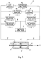
- Figure 3 is a partially block and partially pictorial diagram of a snubber formed in accordance with the present invention.
- the through-rod 43 in Figure 3 is shown in mid-stroke, moving in the door opening direction shown by an arrow 53.
- the flow regulation system 40 comprises first and second conduits 57, 63; first and second flow regulators 59, 65; first and second high pressure relief valves 61, 67; four low pressure check valves 69a, 69b, 69c, 69d; and a spring loaded compensator 71. Overall, the flow regulation system 40 regulates the flow of hydraulic fluid between the compartments 49, 51 located on opposite sides of the piston 45.
- the flow regulation system 40 normally uses the flow regulators 59, 65 to control the rate of fluid transfer between the two compartments 49, 51 but during large applied force conditions, will use high pressure relief valves 61, 67 to quickly dissipate the applied force.
- the high pressure relief valves 61,67 allow the door velocity to increase, thereby limiting the internal forces on the door components, potentially saving those components from yielding or failing.
- each is currently known in the art of snubbing.
- the novelty of the present invention does not reside in these components per se, but rather in the novel use of discrete high pressure relief in conjunction with flow regulation. Since current flow regulators, high pressure relief valves, low pressure check valves, and compensators are well known in the art, no detailed description of these components is provided.
- the flow regulator chosen should be capable of sensing the hydraulic fluid pressure difference between the faces of the snubber piston (or some related value, i.e., the velocity of the snubber through-rod or the applied force to the door) and responding to the sensed input by regulating the flow of hydraulic fluid between the compartments 49, 51.
- the high pressure relief valves include a spring and ball valve that requires a certain threshold pressure in order to compress the spring and allow hydraulic fluid to pass.
- the high pressure relief valve selected should be capable of quickly relieving high pressure hydraulic fluid by rapidly passing hydraulic fluid between the first and second compartments. (Obviously, if a pressure seal is used in the snubbing system it is capable of "blowing out” and thereby acting as a crude high pressure relief element, but that is not what is intended in the present invention. The present invention requires a discrete elementing acting for the purpose of high pressure relief.)
- the high pressure relief valves selected must also reseat, or close, when the high pressure is slightly reduced. Stated differently, the high pressure relief valve should close at roughly the same pressure that it opened, so that very little hysterisis between fluid pressure and through-rod velocity exists.
- the compensator selected should be capable of adding or subtracting hydraulic fluid to or from the snubber to compensate for hydraulic fluid losses or additions (i.e., a slow leak, thermal expansion, etc.)
- the compensator comprises a piston in a housing with hydraulic fluid on one side of the piston and a compression spring on the other side.
- the hydraulic fluid is in communication with a low pressure portion of the flow regulation system 40.
- the spring is in slight compression so that the compensator 71 continually attempts to add hydraulic fluid to the flow regulation system 40, but can just as easily accept excess hydraulic fluid.
- the first compartment 49 contains an outlet that is connected to the first conduit 57.
- the first conduit 57 is branched to reach the inputs of both the first flow regulator 59 and the first high pressure relief valve 61.
- Figure 3 also shows that the third and fourth low pressure check valves 69c, 69d have their outputs connected to the first conduit 57.
- the output of the first flow regulator 59 is connected to the input of the first low pressure check valve 69a, which outputs to the second conduit 63.
- the output of the first high pressure relief valve 61 is connected to a shared passage 80 that connects to the input of the second low pressure check valve 69b.
- the second low pressure check valve 69b also outputs to the second conduit 63.
- the second compartment 51 contains an outlet that is connected to the second conduit 63.
- the second conduit 63 is branched to reach the inputs of both the second flow regulator 65 and the second high pressure relief valve 67.
- the first and second low pressure check valves 69a, 69b have their outputs connected to the second conduit 63, as stated above.
- Downstream of the second flow regulator 65 is the third low pressure check valve 69c, which outputs to the first conduit 57.
- the output of the second high pressure relief valve 67 is connected to the shared passage 80, which connects to the input of the fourth low pressure check valve 69d.
- the fourth low pressure check valve 69d outputs to the first conduit 57.
- the hydraulic fluid port of the compensator 71 is also connected to the shared passage 80.
- the shared passage 80 therefore interconnects five items: the outputs of the first and second high pressure relief valves 61, 67; the inputs of both the first and fourth low pressure check valves 69a, 69d; and the hydraulic port of the compensator 71.
- the optimal position of the compensator 71 for the present invention is between the inputs of the second and fourth low pressure check valves 69b, 69d. In this position, the compensator will see only low pressure. In this position, the compensator will not have to work as hard to add or subtract hydraulic fluid to or from the snubber as it would if it were located in other positions.
- the operation of the flow regulation system 40 is discussed below in three sections: manual door opening operation, manual door closing operation, and actuator door opening operation. Within each section, the discussion includes the response of the system during low applied force conditions through extreme applied force conditions.
- hydraulic fluid flow is defined as going from the first compartment 49 to the second compartment 51 during door opening.
- hydraulic fluid flow is defined as going from the second compartment 51 to the first compartment 49.
- hydraulic fluid flows only from the first conduit 57, through an orifice (not shown) in the first regulator 59, through the first low pressure check valve 69a, through the second conduit 63 to the second chamber 51.
- the pressure in the first conduit 57 is insufficient to open the first high pressure relief valve 61.
- the third and fourth low pressure check valves 69c, 69d prevent hydraulic fluid from entering the outlet ends of either the second flow regulator 65 or the second high pressure relief valve 67.
- the first low pressure check valve 69a prevents smaller forces from creating a transfer of hydraulic fluid. In this manner, hydraulic fluid is passed from the first compartment 49 into the second compartment 51 at a rate controlled by the first flow regulator 59 during low applied force door opening.
- the rate of hydraulic fluid flow through the first flow regulator 59 may be according to any schedule desired by a designer for a particular application.
- the first flow regulator 59 has a shuttle valve (not shown) whose position depends on the difference in hydraulic pressure on opposite sides of the piston. The position of the shuttle valve determines the size of the orifice of the flow regulator. When the pressure difference is below a certain amount, the orifice is fully open. When the pressure increases above a certain valve, the orifice size begins to constrict to a size that keeps the rate of hydraulic fluid flow constant between the first and second compartments 49, 51. Controlling the rate of fluid flow controls the velocity of the piston 45, and the through-rod 43, and thus, the translation of the roller chain pieces 31a, 31b, and the movement of the door.
- the output of the first high pressure relief valve 61 only exits from the shared passage 80 through the second low pressure check valve 69b. This is because the output of the second high pressure relief valve 67 is connected to the shared passage 80.
- the hydraulic pressure in the shared passage 80 is greater than the hydraulic pressure in the second conduit 63, biasing the second high pressure relief valve closed.
- the input of the fourth low pressure check valve 69d is connected to the shared passage 80, the high hydraulic fluid pressure on its output side is greater than that on its input side.
- the fourth low pressure check valve 69d is also biased closed.
- the compensator 71 is only open to the shared passage 80 and does not actually pass hydraulic fluid.
- hydraulic fluid pressure in the first compartment 49 decreases, causing the pressure in the first conduit 57 to decrease. If the hydraulic fluid pressure decreases sufficiently, the first high pressure relief valve 61 will revert back to its closed position. Thereafter, the first flow regulator 59 will operate alone, snubbing the applied force and keeping the hydraulic fluid flow rate, and hence, the door's velocity, at or below an acceptable value.
- hydraulic fluid flows through the second conduit 63, through the second flow regulator 65, through the third low pressure check valve 69c, through the first conduit 57, and into the first compartment 49.
- the first and second low pressure check valves 69a, 69b are unaffected since they are oriented to allow hydraulic fluid to flow into, not out of, the second conduit 63. If the applied force exceeds a predetermined threshold, hydraulic fluid will also flow through the second high pressure relief valve 67, through the shared passage 80, through the fourth low pressure check valve 69d, through the first conduit 57, and into the first compartment 49.
- the output of the second high pressure relief valve 67 will flow only through the fourth low pressure check valve 69d. This is because the differential pressure across the first high pressure relief valve 61 and the second low pressure check valve 69b back biases these valves.
- the compensator 71 is only open to the shared passage 80 and does not actually pass hydraulic fluid.
- Operation during emergency door opening is accomplished in a way similar to manual door opening.
- the linear pneumatic actuator 33 moves the door 11 indirectly by forcing the roller chain pieces 31a, 31b to translate, which rotates the hinge arm connections to the door 11 and the door frame, urging the door to open.
- the snubbing device 41 and the flow regulation system 40 of the present invention snub the applied forces to the door during actuator 33 operation as during manual operation.
- first and second hydraulic fluid conduits 57, 63 each direct fluid to a flow regulator 59, 65 that operates to snub the rate of hydraulic fluid flow between the first and second compartments 49, 51 when low applied forces are present. This prevents the door from moving too quickly.
- the first and second conduits 57, 63 also direct fluid to high pressure relief valves 61, 67 that rapidly dissipate excessive hydraulic fluid pressure when large applied forces are present. This prevents the excessive force from causing the door components to yield or fail.
Landscapes
- Engineering & Computer Science (AREA)
- Mechanical Engineering (AREA)
- Aviation & Aerospace Engineering (AREA)
- General Engineering & Computer Science (AREA)
- Fluid-Pressure Circuits (AREA)
- Fluid-Damping Devices (AREA)
- Power-Operated Mechanisms For Wings (AREA)
Abstract
Description
- The present invention relates to snubbers, and more particularly, to hydraulic snubbers.
- Airplanes rely on specialized doors for passenger boarding and deboarding, galley servicing, cargo loading, maintenance access, emergency egress, etc. Some airplane doors are hinged to the fuselage, others slide into a cavity in the wall of the fuselage, and still others translate by moving outward and then forward along the fuselage of the airplane. During door usage, the possibility exists for various applied forces (such as a pressure difference between the cabin and the outside air, or a high speed wind) to cause an airplane door to rapidly move open or shut. A rapidly moving door is a serious hazard, capable of injuring crew and/or passengers. A rapidly moving airplane door can also cause yielding or failure of the airplane fuselage, door frame, hinge arm, or hinge linkages. In certain instances, a large force applied to a door can completely severe the door's connection to the airplane.
- Snubbers are included in airplane door systems to control the rate of door opening and closing. The primary purpose of a snubber is to enhance personal safety and door integrity by limiting the peak forces applied to the door mechanisms. Snubbers are usually hydraulic devices that absorb energy - similar to shock absorbers. They comprise a housing in the form of a cylinder, a piston mounted in the cylinder, a rod attached to the piston, and hydraulic fluid. Hydraulic fluid flow between chambers located on either side of the piston controls the rate of movement of the piston, and, thus the rod. One commonly used hydraulic fluid flow passageway between the chambers is an orifice in the piston or housing. When a force is exerted upon the rod to urge it in a particular direction, hydraulic fluid flows from one side of the piston to the other side, through the orifice. If the hydraulic fluid flow passageway between the chambers is a simple fixed-size orifice, the rate of fluid flowing from one side of the piston to the other side will be directly proportional to the force applied to the rod. If the hydraulic fluid flow passageway is a flow regulation orifice, the passageway will be provided in a conduit connecting the chambers and the orifice size will be variable. A typical flow regulator maintains a constant rate of fluid flowing through the orifice by adjusting the orifice size. The greater the force being applied to the rod, the smaller the orifice size.
- Operationally, translating airplane doors are supported by a hinge arm rotatably connected at one end to a door frame and at the other end to the door. A roller chain is positioned about a first sprocket mounted on a hinge pin located at one end of the hinge arm and about a second sprocket mounted on a hinge pin located at the other end of the hinge arm. Under non-emergency situations, the door is opened or closed manually. When a manual force is applied to the door, it causes the roller chain to translate, effecting rotation of the door between its open and closed positions. In emergency situations, an actuator is provided to at least power the door open. The actuator is located on one side of the hinge arm, in-line with the roller chain. The actuator includes a through-rod that replaces a portion of the chain. When the actuator is activated, it causes the actuator through-rod to translate. This action causes the roller chain to translate, again effecting rotation of the door from its closed position to its opened position. As the door moves, the door is maintained at an attitude approximately parallel to the longitudinal centerline of the airplane. The velocity of the door is controlled by a snubber installed between the door and the door frame. The snubber collapses onto itself when the door is closed.
- Although snubbers are useful devices, current snubbers have undesirable characteristics. A first such disadvantage (mainly applicable to current linear-type snubbers) is their location in the overall door system. When a snubber is located between two structural points (i.e., the door frame and the door, or the hinge arm and the door), the angle of the snubber relative to the door will change as the door opens or closes. Likewise, the available snubbing force will vary as the door angle varies. The resulting geometry creates sections of door travel in which the snubber is less effective, or sometimes even ineffective. This occurs typically at mid-stroke. While the start and end portions of the door travel path will receive snubbing force, the middle position will receive little or none. This allows the door's velocity to increase during mid-stroke, requiring a large, or "spike", snubbing force at the end of travel to prevent the door from slamming. Many current door snubbers are unable to deal effectively with the spike loads created by snubber-door geometry.
- A second disadvantage of current snubbers (both linear and rotary types) regardless of their location in the overall door system, is that they are frequently unable to dissipate large applied forces in a controlled manner. For example, when a large force is applied to a door while the door is being opened or closed, the door's velocity will increase. Snubbers respond to the door's increased velocity by hydraulically countering the force to prevent the door from moving too rapidly. While a fixed-size orifice snubber will damp the door's velocity, because the orifice remains a constant size, the door speed will still increase in proportion to the amount of force applied to the door. If the applied force is very large, the door's velocity increase will be relatively large. As mentioned above, a rapidly moving door can be a hazard to the crew and/or passengers of an airplane. The rapidly moving door will end its movement by slamming to a stop, potentially causing damage to the airplane fuselage, as well as to the door. To prevent the door from moving rapidly, a snubber with a smaller orifice could be used. However, such a snubber would make the manual operation of the door more difficult and time consuming.
- Flow regulator type snubbers have a partially more desirable response than fixed orifice type snubbers in that they prohibit the door velocity from significantly increasing by providing increased snubbing force to counter increased applied force.
- Regardless of type, any snubber that is unable to dissipate a large applied force quickly enough, results in the application of forces to door components that may cause them to yield or fail. Ideally, the location and design of a snubber should be such that large forces are dissipated in a controlled manner, i.e., provide a balance between too much and too little snubbing. An ideal snubber should be located and designed such that large forces are dissipated fast enough to prevent door components from breaking, but slow enough to stop a door without slamming. The snubber location and design should allow a door to move fast enough to be comfortably moved manually, but slow enough not to injure anyone. Neither the location nor the design of present snubbers meet all of these ideal requirements. Thus, a need exists for a new and improved snubber for a translating airplane door system that is designed and located to provide snubbing force throughout the entire path traveled by the door as it moves between its opened and closed positions, while allowing the door to be easily opened when very little force is applied. The snubber design and location should allow the snubber to counteract large applied forces, in order to slow door movement and prevent possible injury to crew and/or passengers. The snubber should be capable of quickly dissipating extremely large applied forces in order to protect the internal mechanisms of the door from yielding or failing during the door's travel, while preventing a buildup of velocity at the end of the door's travel. The present invention is directed to fulfilling this need.
- In accordance with the present invention, a hydraulic snubber that is ideally suited for use on an airplane translating door hinge arm is provided. The door hinge arm is rotatably attached at one end to the door frame and at the other end to a door by hinge pins. Mounted on the hinge pins are first and second sprockets, one located at each end of the hinge arm. Two roller chain pieces are partially looped around the sprockets, one chain associated with each sprocket. A pneumatic actuator is provided, comprising a housing in the form of a cylinder, a piston mounted in the cylinder, and a through-rod passing through the cylinder and connected to the piston. The actuator through-rod connects one end of one of the roller chains to one end of the other roller chain. The snubber comprises a hydraulic device that joins the other ends of the chains. The hydraulic snubber is located generally parallel to the actuator. The hydraulic device includes a housing in the form of a cylinder, a piston mounted in the cylinder, and a through-rod passing through the cylinder and connected to the piston. The actuator and snubber housings are supported by a support member that is integral with the hinge arm.
- During non-emergency situations, a manually applied force causes the roller chain to translate around the sprockets. This action causes the hinge arm to rotate relative to the door frame, and the door to rotate relative to the hinge arm. In emergency situations, pneumatic pressure is applied to one side of the actuator piston to cause the actuator through-rod to move, which forces the roller chain to translate and the door to open. As the door moves between its closed and opened positions, snubbing force is provided by the hydraulic device.
- In accordance with further aspects of the present invention, the snubber also includes a fluid flow regulation system that controls the amount of snubbing force available, depending on the applied force to the door. The fluid flow regulation system comprises two flow regulators, one for each direction of door travel (i.e., door opening and door closing) during normal operating conditions.
- In accordance with yet other aspects of this invention, the fluid flow regulation system also includes two high pressure relief valves for relieving large applied forces, one for each direction of door travel.
- In accordance with still other aspects of this invention, low pressure check valves are provided throughout the snubber fluid flow regulation system to ensure that the fluid flows through the appropriate fluid path.
- In accordance with still further aspects of this invention, a compensator is provided for hydraulically compensating the snubber for hydraulic leaks, thermal expansion, etc.
- From the foregoing description, it will be appreciated that a new, and distinctly better, snubber whose position and design is ideally suited for use on an airplane translating door hinge arm is provided by the present invention. The location of the hydraulic device between the roller chain pieces allows the snubber to provide snubbing force throughout the entire path traveled by the door, eliminating the application of spike loads to the snubber at the ends of the path of door travel. The flow regulators of the snubber's fluid flow regulation system allow the door to be easily moved by the application of minimal force. The flow regulators increase snubbing capability in response to larger applied forces in order to prevent the door from moving too quickly. The high pressure relief valves of the snubber's fluid flow regulation system dissipate very large applied loads quickly, thereby protecting the internal door mechanisms from yielding or failing. The combination of the flow regulators and the high pressure relief valves prevent a buildup of velocity during the door's travel.
- The foregoing aspects and many of the attendant advantages of this invention will become more readily appreciated as the same becomes better understood by reference to the following detailed description, when taken in conjunction with the accompanying drawings, wherein:
- Figure 1 is an pictorial view of the interior of selected components of an airplane translating passenger door showing the location of a door hinge arm relative to the door and in dashed lines, the location of the hinge arm components that control the movement of the door including a snubber formed in accordance with the present invention;
- Figure 2 is a plan view of the door hinge arm components that control the movement of the door including a snubber formed in accordance with the present invention shown in figure 1; and
- Figure 3 is a partially block and partially pictorial diagram of a hydraulic door snubber formed in accordance with the present invention.
- Although the present invention was developed for, and is described in connection with, an airplane translating passenger entry door, it is to be understood that the invention may also find use in other snubber applications, including other airplane snubber applications, where a large applied force may occur. One example of such a use is to control flutter on an aircraft wing.
- The following paragraphs describe a snubber formed in accordance with the present invention and its preferred location in an airplane translating door system. The snubber is comprised of a
hydraulic device 41 and aflow regulation system 40. The following description focuses first on thehydraulic device 41 in terms of its placement in the overall door system and the operation of the snubber therein. (Shown generally in Figures 1 and 2.) Next, a detailed description of theflow regulation system 40 is given in terms of its elements and the effect those elements have on the performance of the snubber. (Shown generally in Figure 3.) - Figure 1 is a pictorial view of selected components of an airplane translating
passenger door 11. More specifically, Figure 1 shows adoor 11, ahinge arm 13, an operating handle 12, first and second hinge pins 15, 17, adoor bracket 19, translation-producinghinge arm components 20, and thehydraulic device 41 of a snubber formed in accordance with the present invention. Both the operating handle 12 and thehinge arm 13 are located on the side of thedoor 11 internal to the airplane. The operating handle 12 is of a type known in the art. Thedoor hinge arm 13 has a dog-leg shape. Thefirst hinge pin 15 rotatably connects one end of thehinge arm 13 to a door frame bracket (not shown). Thesecond hinge pin 17 rotatably connects the other end of thehinge arm 13 to thedoor bracket 19. Shown in dashed lines in Figure 1 within thehinge arm 13 are the translation-producinghinge arm components 20 that control the movement of the door and thehydraulic device 41. These elements are better seen in Figure 2 and are described next. - Figure 2 is a plan view of the hinge arm components that control the movement of the
door 11 and of the snubberhydraulic device 41. The hinge arm components include first andsecond sprockets roller chain 31a, 31b; and a linearpneumatic actuator 33. Thefirst sprocket 25 is mounted on thefirst hinge pin 15, and thesecond sprocket 27 is mounted on thesecond hinge pin 17. The first idler sprocket 29a is located near the inside turn of the dog-leg shapedhinge arm 13, and the second idler sprocket 29b is located near the outside turn. - One of the
roller chain pieces 31b is positioned about the firsthinge pin sprocket 25 and about the first and second idler sprockets 29a and 29b, thus, encompassing the arm of the dog-leg shapeddoor hinge arm 13 that extends to the frame hinge bracket (not shown). The other piece of roller chain 31a extends around thesprocket 27 mounted on thepin 17 that passes through thedoor hinge bracket 19. The linearpneumatic actuator 33 joins the ends of theroller chain pieces 31a, 31b located on the side of thehinge arm 13 nearest thedoor 11. The snubberhydraulic device 41 of the present invention joins the ends of theroller chain pieces 31a, 31b located on the side of thehinge arm 13 furthest from thedoor 11. - The linear pneumatic actuator 33 (shown in Figure 2) is of a type currently known in the art of airplane door actuators. It generally includes a
cylinder 35, apiston 39, and a through-rod 37. The through-rod 37 is affixed to thepiston 39 and passes through the ends of thecylinder 35. The ends of the through-rod 37 are connected bysuitable couplers roller chain pieces 31a, 31b. Only a chamber in the cylinder on one side of the piston is connected to a source of pneumatic power. The other chamber is not so connected. Thus, the pneumatic actuator is a unidirectional actuator, the actuation direction being the door open direction. Since unidirectionalpneumatic actuators 33 capable of opening an airplane door and not interfering with the closing of the door are known, no specific actuator designed to accomplish these functions is described here. - The
hydraulic device 41 of the snubber includes a housing in the form of acylinder 47, apiston 45 and a through-rod 43. The through-rod 43 is affixed to thepiston 45 and passes through the ends of thecylinder 47. The ends of the through-rod 43 are connected bysuitable couplers 44a, 44b to the above-described ends of each of theroller chain pieces 31a, 31b. Thecylinder 47 and thepiston 45 together define first and second hydraulic fluid compartments 49, 51, one located on either side of thepiston 45. - In the preferred embodiment, during non-emergency operations, the door is opened by manually rotating the door handle 12 to unlock the door, and manually applying a force to move the
door 11 open. In emergencies, the rotation of the door handle 12 causes the linearpneumatic actuator 33 to crate the force that translates the door open. The linearpneumatic actuator 33 is activated by a door system that does not form part of the present invention and thus is not described here. As noted above, preferably the linear pneumatic actuator operates only to open the door during emergencies and does not interfere with the manual closing of the door. - In more detail, when a manual force is applied to open or close the door, the
roller chain pieces 31a, 31b translate around thesprockets roller chain 31b moves in one direction or the other around thefirst sprocket 25, thehinge arm 13 is caused to rotate around the hinge connection at the door frame. At the same time, the roller chain piece 31a is also revolving around thesecond sprocket 27, causing it to pivot thedoor 11, via thedoor bracket 19. As theroller chain pieces 31a, 31b translate along thehinge arm 13, thehinge arm 13 maintains the door's attitude approximately parallel to the longitudinal centerline of the airplane. Therefore, as the manually applied force moves the door, but the translation of the roller chain pieces synchronizes the rotation of the hinge arm to the door with the rotation of the hinge arm to the door frame, which causes the door to move along a path that maintains the door parallel to the airplane fuselage. If the pneumatic actuator is used to open the door, the actuator through-rod 37 causes theroller chain pieces 31a and 31b to translate and indirectly open the door. - All forces applied to the
roller chain pieces 31a, 31b (vis-à-vis thedoor 11 and/or the pneumatic actuator 33) are snubbed by thehydraulic device 41 under the control of, and according to, aflow regulation system 40. Theflow regulation system 40 is shown in block form in Figure 3, and is described below. - Figure 3 is a partially block and partially pictorial diagram of a snubber formed in accordance with the present invention. The through-
rod 43 in Figure 3 is shown in mid-stroke, moving in the door opening direction shown by anarrow 53. Theflow regulation system 40 comprises first andsecond conduits second flow regulators pressure relief valves pressure check valves 69a, 69b, 69c, 69d; and a spring loadedcompensator 71. Overall, theflow regulation system 40 regulates the flow of hydraulic fluid between thecompartments piston 45. Theflow regulation system 40 normally uses theflow regulators compartments pressure relief valves pressure relief valves - Below is a description of the
flow regulation system 40. First, a discussion of the components is presented. Next, the components are described in terms of their physical relation to one another. Lastly, a description of their operation is provided. - With regard to the components of the
flow regulation system 40, each is currently known in the art of snubbing. The novelty of the present invention does not reside in these components per se, but rather in the novel use of discrete high pressure relief in conjunction with flow regulation. Since current flow regulators, high pressure relief valves, low pressure check valves, and compensators are well known in the art, no detailed description of these components is provided. - The specific components selected for use in the present invention should be capable of performing as described herein. In particular, the flow regulator chosen should be capable of sensing the hydraulic fluid pressure difference between the faces of the snubber piston (or some related value, i.e., the velocity of the snubber through-rod or the applied force to the door) and responding to the sensed input by regulating the flow of hydraulic fluid between the
compartments - The high pressure relief valve selected should be capable of quickly relieving high pressure hydraulic fluid by rapidly passing hydraulic fluid between the first and second compartments. (Obviously, if a pressure seal is used in the snubbing system it is capable of "blowing out" and thereby acting as a crude high pressure relief element, but that is not what is intended in the present invention. The present invention requires a discrete elementing acting for the purpose of high pressure relief.) The high pressure relief valves selected must also reseat, or close, when the high pressure is slightly reduced. Stated differently, the high pressure relief valve should close at roughly the same pressure that it opened, so that very little hysterisis between fluid pressure and through-rod velocity exists.
- The compensator selected should be capable of adding or subtracting hydraulic fluid to or from the snubber to compensate for hydraulic fluid losses or additions (i.e., a slow leak, thermal expansion, etc.) In the preferred embodiment, the compensator comprises a piston in a housing with hydraulic fluid on one side of the piston and a compression spring on the other side. The hydraulic fluid is in communication with a low pressure portion of the
flow regulation system 40. The spring is in slight compression so that thecompensator 71 continually attempts to add hydraulic fluid to theflow regulation system 40, but can just as easily accept excess hydraulic fluid. - With regard to the physical relation of the components, the
first compartment 49 contains an outlet that is connected to thefirst conduit 57. Thefirst conduit 57 is branched to reach the inputs of both thefirst flow regulator 59 and the first highpressure relief valve 61. Figure 3 also shows that the third and fourth lowpressure check valves 69c, 69d have their outputs connected to thefirst conduit 57. The output of thefirst flow regulator 59 is connected to the input of the first low pressure check valve 69a, which outputs to thesecond conduit 63. The output of the first highpressure relief valve 61 is connected to a sharedpassage 80 that connects to the input of the second low pressure check valve 69b. The second low pressure check valve 69b also outputs to thesecond conduit 63. - The above described connections are provided for use during door opening. For door closing, similar component connections are provided. Specifically, the
second compartment 51 contains an outlet that is connected to thesecond conduit 63. Thesecond conduit 63 is branched to reach the inputs of both thesecond flow regulator 65 and the second highpressure relief valve 67. The first and second low pressure check valves 69a, 69b have their outputs connected to thesecond conduit 63, as stated above. Downstream of thesecond flow regulator 65 is the third low pressure check valve 69c, which outputs to thefirst conduit 57. The output of the second highpressure relief valve 67 is connected to the sharedpassage 80, which connects to the input of the fourth lowpressure check valve 69d. The fourth lowpressure check valve 69d outputs to thefirst conduit 57. The hydraulic fluid port of thecompensator 71 is also connected to the sharedpassage 80. Thus, the sharedpassage 80 therefore interconnects five items: the outputs of the first and second highpressure relief valves pressure check valves 69a, 69d; and the hydraulic port of thecompensator 71. It is well known in the art to place compensators in a number of different locations within a snubber. The location is not important to the present invention. The optimal position of thecompensator 71 for the present invention is between the inputs of the second and fourth lowpressure check valves 69b, 69d. In this position, the compensator will see only low pressure. In this position, the compensator will not have to work as hard to add or subtract hydraulic fluid to or from the snubber as it would if it were located in other positions. - The operation of the
flow regulation system 40 is discussed below in three sections: manual door opening operation, manual door closing operation, and actuator door opening operation. Within each section, the discussion includes the response of the system during low applied force conditions through extreme applied force conditions. - During door opening, the force applied to the door also pushes the through-
rod 43 andpiston 45 of the snubberhydraulic device 47. Thepiston 45 forces hydraulic fluid from thefirst compartment 49 to flow into thefirst conduit 57. (For explanatory purposes, hydraulic fluid flow is defined as going from thefirst compartment 49 to thesecond compartment 51 during door opening. Likewise, during door closing, hydraulic fluid flow is defined as going from thesecond compartment 51 to thefirst compartment 49.) - When a low applied force occurs during door opening, hydraulic fluid flows only from the
first conduit 57, through an orifice (not shown) in thefirst regulator 59, through the first low pressure check valve 69a, through thesecond conduit 63 to thesecond chamber 51. The pressure in thefirst conduit 57 is insufficient to open the first highpressure relief valve 61. The third and fourth lowpressure check valves 69c, 69d prevent hydraulic fluid from entering the outlet ends of either thesecond flow regulator 65 or the second highpressure relief valve 67. In addition to preventing hydraulic fluid from entering the first flow regulator from thesecond conduit 63, the first low pressure check valve 69a prevents smaller forces from creating a transfer of hydraulic fluid. In this manner, hydraulic fluid is passed from thefirst compartment 49 into thesecond compartment 51 at a rate controlled by thefirst flow regulator 59 during low applied force door opening. - The rate of hydraulic fluid flow through the
first flow regulator 59 may be according to any schedule desired by a designer for a particular application. Preferably, thefirst flow regulator 59 has a shuttle valve (not shown) whose position depends on the difference in hydraulic pressure on opposite sides of the piston. The position of the shuttle valve determines the size of the orifice of the flow regulator. When the pressure difference is below a certain amount, the orifice is fully open. When the pressure increases above a certain valve, the orifice size begins to constrict to a size that keeps the rate of hydraulic fluid flow constant between the first andsecond compartments piston 45, and the through-rod 43, and thus, the translation of theroller chain pieces 31a, 31b, and the movement of the door. - When a very large external dynamic force is applied to the door during opening (such as caused by wind, pressure, airplane attitude, etc.), a very large pressure difference exists across the faces of the
piston 45. This causes the orifice of thefirst flow regulator 59 to constrict to a very small opening. Depending upon the force, the hydraulic fluid pressure in thefirst conduit 57 may be large enough to exceed the opening threshold of the first highpressure relief valve 61. When this threshold is reached, hydraulic fluid begins to pass through the first highpressure relief valve 61. Fluid passing through the highpressure relief valve 61 enters the sharedpassage 80, passes through the second low pressure check valve 69b and thesecond conduit 63 into thesecond compartment 51. The first highpressure relief valve 61 adds an additional path through which hydraulic fluid quickly passes, dissipating excessive hydraulic fluid pressure by rapidly transferring fluid from thefirst compartment 49 to thesecond compartment 51. - As a side note, even though the shared
passage 80 is connected to multiple components, the output of the first highpressure relief valve 61 only exits from the sharedpassage 80 through the second low pressure check valve 69b. This is because the output of the second highpressure relief valve 67 is connected to the sharedpassage 80. The hydraulic pressure in the sharedpassage 80 is greater than the hydraulic pressure in thesecond conduit 63, biasing the second high pressure relief valve closed. While the input of the fourth lowpressure check valve 69d is connected to the sharedpassage 80, the high hydraulic fluid pressure on its output side is greater than that on its input side. Thus, the fourth lowpressure check valve 69d is also biased closed. Thecompensator 71 is only open to the sharedpassage 80 and does not actually pass hydraulic fluid. - If the large applied force is reduced during door opening, hydraulic fluid pressure in the
first compartment 49 decreases, causing the pressure in thefirst conduit 57 to decrease. If the hydraulic fluid pressure decreases sufficiently, the first highpressure relief valve 61 will revert back to its closed position. Thereafter, thefirst flow regulator 59 will operate alone, snubbing the applied force and keeping the hydraulic fluid flow rate, and hence, the door's velocity, at or below an acceptable value. - Identical regulation is provided for manual door closing. In this case, hydraulic fluid flows through the
second conduit 63, through thesecond flow regulator 65, through the third low pressure check valve 69c, through thefirst conduit 57, and into thefirst compartment 49. The first and second low pressure check valves 69a, 69b are unaffected since they are oriented to allow hydraulic fluid to flow into, not out of, thesecond conduit 63. If the applied force exceeds a predetermined threshold, hydraulic fluid will also flow through the second highpressure relief valve 67, through the sharedpassage 80, through the fourth lowpressure check valve 69d, through thefirst conduit 57, and into thefirst compartment 49. Again, even though the sharedpassage 80 is connected to multiple components, the output of the second highpressure relief valve 67 will flow only through the fourth lowpressure check valve 69d. This is because the differential pressure across the first highpressure relief valve 61 and the second low pressure check valve 69b back biases these valves. Thecompensator 71 is only open to the sharedpassage 80 and does not actually pass hydraulic fluid. - Operation during emergency door opening is accomplished in a way similar to manual door opening. The significant difference being that instead of a manual force directly causing the movement of the door, the linear
pneumatic actuator 33 moves thedoor 11 indirectly by forcing theroller chain pieces 31a, 31b to translate, which rotates the hinge arm connections to thedoor 11 and the door frame, urging the door to open. The snubbingdevice 41 and theflow regulation system 40 of the present invention snub the applied forces to the door duringactuator 33 operation as during manual operation. - In summary, the first and second hydraulic
fluid conduits flow regulator second compartments second conduits pressure relief valves - While the presently preferred embodiment of the invention has been illustrated and described, it will be appreciated that various changes can be made therein without departing from the spirit and scope of the invention. For example, as noted above, while the illustrated and described snubber has been described in an airplane door translating system, it is to be understood that the snubber may find use in other environments, including other airplane environments, Further, in some airplane and other door environments, an actuator, such as the pneumatic actuator, may be unnecessary, in which use the related ends of the chains would be connected together. Further, in some environments, the chain and sprockets could be replaced by belts and pulleys. Hence, it is to be understood that, within the scope of the appended claims, this invention can be practiced otherwise than as specifically described herein.
Claims (10)
- A translating door system that includes a hinge arm (13) having first and second ends, first and second sprockets (25, 27), the first sprocket (25) being rotatably attached to the first end of the hinge arm (13), the second sprocket (27) being rotatably attached to the second end of the hinge arm (13), and a roller chain (31a, 31b) wrapped around the first and second sprockets (25, 27), and having first and second ends, characterized by a snubber, said snubber including:(a) a hydraulic device (41) including a housing (27), a piston (45) located in the housing (47), and a through-rod (43) connected to the piston (45) and extending through the housing (47), the ends of the through-rod (43) being coupled to the first and second ends of the roller chain (31a, 31b); the housing (47) and the piston (45) defining two hydraulic fluid compartments (49, 51) located on opposite sides of the piston (45), and(b) a flow regulation system (40) in fluid communication with the two hydraulic fluid compartments (49, 51) for snubbing the movement of the hinge arm (13) by controlling the rate of hydraulic fluid flow between the first and second fluid compartments (49, 51).
- The translating door system claimed in claim 1, characterized in that the hinge arm (13) has a dog leg shape and the snubber hydraulic device (41) is located on the outer side of the dog leg shaped hinge arm (13).
- The translating door system claimed in claim 1 or 2, characterized in that the flow regulation system (40) includes at least one flow regulator (59, 65).
- The translating door system claimed in any of one of the preceding claims, characterized in that the flow regulation system (40) also includes at least one high pressure relief valve (61, 67) for relieving excessive forces applied to the door (11).
- The translating door system claimed in any one of the preceding claims, characterized in that the flow regulation system (40) comprises:(a) a first fluid conduit (57) in communication with the first fluid compartment (49);(b) a second fluid conduit (63) in communication with the second fluid compartment (51);(c) first and second low pressure check valves (69a, 69b), each having an input side and an output side;(d) a first flow regulator (59) for controlling the rate of hydraulic fluid passing from the first fluid compartment (49) to the second fluid compartment (51), the first flow regulator (59) having an input side connected to the first fluid conduit (53) and an output side connected to the input side of the first low pressure check valve (69a), the output side of the first low pressure check valve (69a) being connected to the second fluid conduit (63);(e) a fluid passage (80); and(f) a first high pressure relief valve (61) for relieving excessive hydraulic fluid pressure between the first fluid compartment (49) and the second fluid compartment (51), the first high pressure relief valve (61) having an input side connected to the first fluid conduit (57) and an output side connected to the fluid passage (80), the fluid passage (80) being additionally connected to the input side of the second low pressure check valve (69b), the output side of the second low pressure check valve (69b) being connected to the second fluid conduit (63).
- The translating door system claimed in claim 5, characterized by a compensator (71) connected to the fluid passage (80) for hydraulically compensating the flow regulation system (40).
- The translating door system claimed in claim 5 or 6, characterized by:(a) third and fourth low pressure check valves (69c, 69d), each having an input side and an output side;(b) a second flow regulator (65) for controlling the rate of hydraulic fluid passing from the second fluid compartment (5@) to the first fluid compartment (49), the second flow regulator (65) having an input side connected to the second fluid conduit (63) and an output side connected to the input side of the third low pressure check valve (69c), the output side of the third low pressure check valve (69c) being connected to the first fluid conduit (57); and(c) a second high pressure relief valve (67) for relieving excessive hydraulic fluid pressure between the second fluid compartment (51) and the first fluid compartment (49), the second high pressure relief valve (67) having an input side connected to the second fluid conduit (63) and an output side connected to the fluid passage (80), the fluid passage (80) being additionally connected to the input side of the fourth low pressure check valve (69d), the output side of the fourth low pressure check valve (69d) being connected to the first fluid conduit (57).
- A flow regulation system (40) for a snubber hydraulic device (41) having first and second fluid compartments (49, 51), the flow regulation system (40) comprising:(a) a first fluid conduit (57) in communication with the first fluid compartment (49);(b) a second fluid conduit (63) in communication with the second fluid compartment (51);(c) first and second low pressure check valves (69a, 69b), each having an input side and an output side;(d) a first flow regulator (59) for controlling the rate of hydraulic fluid passing from the first fluid compartment (49) to the second fluid compartment (51), the first flow regulator (59) having an input side connected to the first fluid conduit (53) and an output side connected to the input side of the first low pressure check valve (69a), the output side of the first low pressure check valve (69a) being connected to the second fluid conduit (63);(e) a fluid passage (80); and(f) a first high pressure relief valve (61) for relieving excessive hydraulic fluid pressure between the first fluid compartment (49) and the second fluid compartment (51), the first high pressure relief valve (61) having an input side connected to the first fluid conduit (57) and an output side connected to the fluid passage (80), the fluid passage (80) being additionally connected to the input side of the second low pressure check valve (69b), the output side of the second low pressure check valve (69b) being connected to the second fluid conduit (63).
- The flow regulation system (49) for a snubber hydraulic device (41) according to claim 8, characterized by a compensator (71) connected to the fluid passage (80) for hydraulically compensating the flow regulation system (40).
- The flow regulation system (40) for a snubber hydraulic device (41) according to claim 8 or 9, characterized by:(a) third an fourth low pressure check valves (69c, 69d), each having an input side and an output side;(b) a second flow regulator (65) for controlling the rate of hydraulic fluid passing from the second fluid compartment (51) to the first fluid compartment (49), the second flow regulator (65) having an input side connected to the second fluid conduit (63) and an output side connected to the input side of the third low pressure check valve (69c), the output side of the third low pressure check valve (69c) being connected to the first fluid conduit (57); and(c) a second high pressure relief valve (67) for relieving excessive hydraulic fluid pressure between the second fluid compartment (51) and the first fluid compartment (49), the second high pressure relief valve (67) having an input side connected to the second fluid conduit (63) and an output side connected to the fluid passage (80), the fluid passage (80) being additionally connected to the input side of the fourth low pressure check valve (69d), the output side of the fourth low pressure check valve (69d) being connected to the first fluid conduit (57).
Applications Claiming Priority (2)
| Application Number | Priority Date | Filing Date | Title |
|---|---|---|---|
| US432846 | 1995-05-02 | ||
| US08/432,846 US5687452A (en) | 1995-05-02 | 1995-05-02 | Hydraulic snubber for aircraft |
Publications (2)
| Publication Number | Publication Date |
|---|---|
| EP0741073A1 true EP0741073A1 (en) | 1996-11-06 |
| EP0741073B1 EP0741073B1 (en) | 2002-03-27 |
Family
ID=23717826
Family Applications (1)
| Application Number | Title | Priority Date | Filing Date |
|---|---|---|---|
| EP95202997A Expired - Lifetime EP0741073B1 (en) | 1995-05-02 | 1995-11-06 | Snubbing system for airplane translating door |
Country Status (3)
| Country | Link |
|---|---|
| US (1) | US5687452A (en) |
| EP (1) | EP0741073B1 (en) |
| DE (1) | DE69526068T2 (en) |
Cited By (11)
| Publication number | Priority date | Publication date | Assignee | Title |
|---|---|---|---|---|
| EP1300334A1 (en) | 2001-10-05 | 2003-04-09 | Airbus France | Emergency opening device and method for an aircraft escape door |
| FR2836120A1 (en) * | 2002-02-20 | 2003-08-22 | Eurocopter Deutschland | DRIVE MEANS FOR PIVOTING A PIVOTED MOUNTED AIRCRAFT DOOR ON A SUPPORT ARM |
| EP1544098A1 (en) * | 2003-12-19 | 2005-06-22 | Etienne Lacroix - Tous Artifices Sa | Actuation device for the deplacement of a closure element for vehicles |
| US9327820B2 (en) | 2011-05-31 | 2016-05-03 | Latecoere | Emergency opening device for an aircraft door |
| WO2017042165A1 (en) | 2015-09-07 | 2017-03-16 | Latecoere | Emergency opening system and method for an aircraft emergency door |
| WO2017056036A1 (en) | 2015-10-02 | 2017-04-06 | Latecoere | Opening system and method for an aircraft emergency door |
| WO2020020861A1 (en) | 2018-07-24 | 2020-01-30 | Latecoere | Device for opening an aircraft door in emergencies, said device having a lever-type retention member |
| WO2020020866A1 (en) | 2018-07-24 | 2020-01-30 | Latecoere | Emergency opening device for an aircraft door, comprising a retaining member with a hook |
| WO2020020860A1 (en) | 2018-07-24 | 2020-01-30 | Latecoere | Emergency opening device for an aircraft door, comprising a telescopic operating member |
| WO2020074449A1 (en) | 2018-10-10 | 2020-04-16 | Latecoere | Method for opening/closing an aircraft door and aircraft implementing such a method |
| US11912399B2 (en) | 2022-02-18 | 2024-02-27 | Goodrich Corporation | Compact aircraft actuator system |
Families Citing this family (11)
| Publication number | Priority date | Publication date | Assignee | Title |
|---|---|---|---|---|
| US7146766B2 (en) * | 2004-03-16 | 2006-12-12 | Manitowoc Foodservice Companies, Inc. | Door control assembly |
| US7357354B2 (en) | 2005-03-11 | 2008-04-15 | The Boeing Company | Aircraft door hinge assembly |
| WO2009073810A2 (en) * | 2007-12-05 | 2009-06-11 | Pacific Scientific Company | Snubber valve |
| US8225815B2 (en) * | 2009-05-19 | 2012-07-24 | Eaton Corporation | Fluid flow regulator |
| US9051758B2 (en) | 2013-07-19 | 2015-06-09 | The Boeing Company | Door snubber and strike plate |
| AT515354A1 (en) * | 2014-01-21 | 2015-08-15 | Facc Ag | Device for opening an aircraft door |
| US9470285B2 (en) * | 2014-04-08 | 2016-10-18 | The Boeing Company | Aircraft door dampening system |
| DE102018121307B4 (en) * | 2018-08-31 | 2020-07-02 | Airbus Operations Gmbh | Airplane door lock, airplane door and airplane with an airplane door |
| US11691710B2 (en) * | 2020-04-07 | 2023-07-04 | The Boeing Company | Double translating plug-type passenger entry door |
| US11725710B2 (en) * | 2020-06-04 | 2023-08-15 | The Boeing Company | Variable fluid damping |
| FR3142449A1 (en) * | 2022-11-29 | 2024-05-31 | Airbus Canada Limited Partnership | Remote closing and opening system for a door intended for an access opening of an aircraft fuselage and remote closing method. |
Citations (6)
| Publication number | Priority date | Publication date | Assignee | Title |
|---|---|---|---|---|
| GB1452334A (en) * | 1973-10-30 | 1976-10-13 | Boeing Co | Aircraft doors |
| GB2128672A (en) * | 1982-10-13 | 1984-05-02 | Fokker Bv | Two-stage pivoting of aircraft door |
| DE3939485A1 (en) * | 1989-11-29 | 1990-04-05 | Rainer Dipl Ing Daumann | Motor vehicle shock absorber - has device to increase damping force as load on vehicle increases |
| US5289615A (en) * | 1991-11-08 | 1994-03-01 | The Boeing Company | Aircraft door hinge mechanism |
| DE4417796A1 (en) * | 1993-05-20 | 1994-12-01 | Tokico Ltd | Hydraulic shock absorber with adjustable damping force |
| US5379971A (en) * | 1993-12-22 | 1995-01-10 | The Boeing Company | Emergency power system for door |
Family Cites Families (6)
| Publication number | Priority date | Publication date | Assignee | Title |
|---|---|---|---|---|
| US3561574A (en) * | 1969-04-25 | 1971-02-09 | Mcdowell Wellman Eng Co | Fluid flow control device |
| US3638885A (en) * | 1970-03-09 | 1972-02-01 | Boeing Co | Lag frequency selective damper |
| US3739808A (en) * | 1972-01-13 | 1973-06-19 | Milwaukee Cylinder Corp | Hydraulic shock damping device |
| US4084668A (en) * | 1975-06-05 | 1978-04-18 | United Technologies Corporation | Redundant damper seals |
| US5178240A (en) * | 1985-05-23 | 1993-01-12 | Enidine Incorporated | Adjustable double-acting damper |
| US5529152A (en) * | 1994-07-08 | 1996-06-25 | Aimrite Systems International, Inc. | Variable constant force hydraulic components and systems |
-
1995
- 1995-05-02 US US08/432,846 patent/US5687452A/en not_active Expired - Lifetime
- 1995-11-06 EP EP95202997A patent/EP0741073B1/en not_active Expired - Lifetime
- 1995-11-06 DE DE69526068T patent/DE69526068T2/en not_active Expired - Lifetime
Patent Citations (6)
| Publication number | Priority date | Publication date | Assignee | Title |
|---|---|---|---|---|
| GB1452334A (en) * | 1973-10-30 | 1976-10-13 | Boeing Co | Aircraft doors |
| GB2128672A (en) * | 1982-10-13 | 1984-05-02 | Fokker Bv | Two-stage pivoting of aircraft door |
| DE3939485A1 (en) * | 1989-11-29 | 1990-04-05 | Rainer Dipl Ing Daumann | Motor vehicle shock absorber - has device to increase damping force as load on vehicle increases |
| US5289615A (en) * | 1991-11-08 | 1994-03-01 | The Boeing Company | Aircraft door hinge mechanism |
| DE4417796A1 (en) * | 1993-05-20 | 1994-12-01 | Tokico Ltd | Hydraulic shock absorber with adjustable damping force |
| US5379971A (en) * | 1993-12-22 | 1995-01-10 | The Boeing Company | Emergency power system for door |
Cited By (22)
| Publication number | Priority date | Publication date | Assignee | Title |
|---|---|---|---|---|
| EP1300334A1 (en) | 2001-10-05 | 2003-04-09 | Airbus France | Emergency opening device and method for an aircraft escape door |
| FR2830564A1 (en) | 2001-10-05 | 2003-04-11 | Airbus France | DEVICE AND METHOD FOR CONTROLLING THE EMERGENCY OPENING OF AN AIRCRAFT EXHAUST DOOR |
| US6752356B2 (en) | 2001-10-05 | 2004-06-22 | Airbus France | Control device and method for emergency opening of an aircraft evacuation door |
| US6786454B2 (en) | 2001-10-05 | 2004-09-07 | Airbus France | Control device and method for emergency opening of an aircraft evacuation door |
| FR2836120A1 (en) * | 2002-02-20 | 2003-08-22 | Eurocopter Deutschland | DRIVE MEANS FOR PIVOTING A PIVOTED MOUNTED AIRCRAFT DOOR ON A SUPPORT ARM |
| EP1544098A1 (en) * | 2003-12-19 | 2005-06-22 | Etienne Lacroix - Tous Artifices Sa | Actuation device for the deplacement of a closure element for vehicles |
| FR2864021A1 (en) * | 2003-12-19 | 2005-06-24 | Lacroix Soc E | DEVICE FOR CONTROLLING THE MOTION OF A CLOSURE MEMBER FOR A VEHICLE |
| US7168659B2 (en) | 2003-12-19 | 2007-01-30 | Etienne Lacroix Tous Artifices | Control device for moving a vehicle closure element |
| US9327820B2 (en) | 2011-05-31 | 2016-05-03 | Latecoere | Emergency opening device for an aircraft door |
| WO2017042165A1 (en) | 2015-09-07 | 2017-03-16 | Latecoere | Emergency opening system and method for an aircraft emergency door |
| WO2017056036A1 (en) | 2015-10-02 | 2017-04-06 | Latecoere | Opening system and method for an aircraft emergency door |
| US11198498B2 (en) | 2015-10-02 | 2021-12-14 | Latecoere | Opening system and method for an aircraft emergency door |
| WO2020020861A1 (en) | 2018-07-24 | 2020-01-30 | Latecoere | Device for opening an aircraft door in emergencies, said device having a lever-type retention member |
| WO2020020866A1 (en) | 2018-07-24 | 2020-01-30 | Latecoere | Emergency opening device for an aircraft door, comprising a retaining member with a hook |
| WO2020020860A1 (en) | 2018-07-24 | 2020-01-30 | Latecoere | Emergency opening device for an aircraft door, comprising a telescopic operating member |
| US11745845B2 (en) | 2018-07-24 | 2023-09-05 | Latecoere | Emergency opening device for an aircraft door, comprising a telescopic operating member |
| US11781357B2 (en) | 2018-07-24 | 2023-10-10 | Latecoere | Emergency opening device for an aircraft door, comprising a retaining member with a hook |
| US11781356B2 (en) | 2018-07-24 | 2023-10-10 | Latecoere | Device for opening an aircraft door in emergencies, said device having a lever-type retention member |
| WO2020074449A1 (en) | 2018-10-10 | 2020-04-16 | Latecoere | Method for opening/closing an aircraft door and aircraft implementing such a method |
| FR3087189A1 (en) | 2018-10-10 | 2020-04-17 | Latecoere | METHOD FOR OPENING / CLOSING AN AIRCRAFT DOOR AND AIRCRAFT FOR IMPLEMENTING SUCH A METHOD |
| US11661168B2 (en) | 2018-10-10 | 2023-05-30 | Latecoere | Method for opening/closing an aircraft door and aircraft implementing such a method |
| US11912399B2 (en) | 2022-02-18 | 2024-02-27 | Goodrich Corporation | Compact aircraft actuator system |
Also Published As
| Publication number | Publication date |
|---|---|
| DE69526068D1 (en) | 2002-05-02 |
| DE69526068T2 (en) | 2002-12-19 |
| US5687452A (en) | 1997-11-18 |
| EP0741073B1 (en) | 2002-03-27 |
Similar Documents
| Publication | Publication Date | Title |
|---|---|---|
| EP0741073B1 (en) | Snubbing system for airplane translating door | |
| US4422605A (en) | Reverser for jet engine | |
| US5379971A (en) | Emergency power system for door | |
| US6484969B2 (en) | Lowerable baggage compartment for a passenger cabin | |
| US4496121A (en) | Control surface lock for flutter constraint | |
| US4825644A (en) | Ventilation system for a nacelle | |
| US10293949B2 (en) | Inflation system pressure regulator with leakage vent | |
| US20100024161A1 (en) | Hold Open Rod | |
| US2811227A (en) | Flutter damper | |
| EP1873430A2 (en) | Reversed actuator with minimal leak potential | |
| EP1727013B1 (en) | Fluid flow regulator with overpressure relief function | |
| CA1286567C (en) | Automatic valve with high-speed opening | |
| US2286516A (en) | Airfoil hinge | |
| EP3786056B1 (en) | Methods and apparatus for mitigating aerodynamic flutter of aircraft wing flaps | |
| US20130118624A1 (en) | Sealed flapper diverter valve | |
| US12473080B2 (en) | Counterbalanced retract actuator for landing gear | |
| US20090007974A1 (en) | Valve for Allocating Available Fluid To High Priority Functions of a Hydraulic System | |
| US3956971A (en) | Stabilized hydromechanical servo system | |
| CA2974287C (en) | Compressor surge protection | |
| IT202000005749A1 (en) | VALVE FOR FUEL CELL SELF-TRACTION SYSTEMS WITH SECONDARY SAFETY DEVICE | |
| US12123354B2 (en) | Cooling system of a compartment of pieces of equipment in a nacelle of an aircraft propelling assembly | |
| KR930004088Y1 (en) | Floor hinge | |
| CN110273717A (en) | Turbomachinery and its mechanical axial displacement limiting device | |
| US2957458A (en) | Cowl flap actuating mechanism | |
| US3175576A (en) | Valve assembly |
Legal Events
| Date | Code | Title | Description |
|---|---|---|---|
| PUAI | Public reference made under article 153(3) epc to a published international application that has entered the european phase |
Free format text: ORIGINAL CODE: 0009012 |
|
| AK | Designated contracting states |
Kind code of ref document: A1 Designated state(s): DE FR GB |
|
| 17P | Request for examination filed |
Effective date: 19970408 |
|
| 17Q | First examination report despatched |
Effective date: 19981126 |
|
| GRAG | Despatch of communication of intention to grant |
Free format text: ORIGINAL CODE: EPIDOS AGRA |
|
| GRAG | Despatch of communication of intention to grant |
Free format text: ORIGINAL CODE: EPIDOS AGRA |
|
| GRAH | Despatch of communication of intention to grant a patent |
Free format text: ORIGINAL CODE: EPIDOS IGRA |
|
| GRAH | Despatch of communication of intention to grant a patent |
Free format text: ORIGINAL CODE: EPIDOS IGRA |
|
| REG | Reference to a national code |
Ref country code: GB Ref legal event code: IF02 |
|
| GRAA | (expected) grant |
Free format text: ORIGINAL CODE: 0009210 |
|
| AK | Designated contracting states |
Kind code of ref document: B1 Designated state(s): DE FR GB |
|
| REF | Corresponds to: |
Ref document number: 69526068 Country of ref document: DE Date of ref document: 20020502 |
|
| PLBE | No opposition filed within time limit |
Free format text: ORIGINAL CODE: 0009261 |
|
| STAA | Information on the status of an ep patent application or granted ep patent |
Free format text: STATUS: NO OPPOSITION FILED WITHIN TIME LIMIT |
|
| 26N | No opposition filed |
Effective date: 20021230 |
|
| PGFP | Annual fee paid to national office [announced via postgrant information from national office to epo] |
Ref country code: GB Payment date: 20141127 Year of fee payment: 20 Ref country code: DE Payment date: 20141128 Year of fee payment: 20 Ref country code: FR Payment date: 20141118 Year of fee payment: 20 |
|
| REG | Reference to a national code |
Ref country code: DE Ref legal event code: R071 Ref document number: 69526068 Country of ref document: DE |
|
| REG | Reference to a national code |
Ref country code: GB Ref legal event code: PE20 Expiry date: 20151105 |
|
| PG25 | Lapsed in a contracting state [announced via postgrant information from national office to epo] |
Ref country code: GB Free format text: LAPSE BECAUSE OF EXPIRATION OF PROTECTION Effective date: 20151105 |