EP0743883B1 - Device for rinsing objects - Google Patents
Device for rinsing objects Download PDFInfo
- Publication number
- EP0743883B1 EP0743883B1 EP95938000A EP95938000A EP0743883B1 EP 0743883 B1 EP0743883 B1 EP 0743883B1 EP 95938000 A EP95938000 A EP 95938000A EP 95938000 A EP95938000 A EP 95938000A EP 0743883 B1 EP0743883 B1 EP 0743883B1
- Authority
- EP
- European Patent Office
- Prior art keywords
- reservoir
- valve
- housing section
- liquid
- holder
- Prior art date
- Legal status (The legal status is an assumption and is not a legal conclusion. Google has not performed a legal analysis and makes no representation as to the accuracy of the status listed.)
- Expired - Lifetime
Links
- 239000007788 liquid Substances 0.000 claims abstract description 38
- 239000000356 contaminant Substances 0.000 claims description 6
- 230000000994 depressogenic effect Effects 0.000 claims description 3
- 238000005086 pumping Methods 0.000 claims description 3
- 238000004140 cleaning Methods 0.000 description 6
- 239000000945 filler Substances 0.000 description 2
- 238000007789 sealing Methods 0.000 description 2
- 230000000881 depressing effect Effects 0.000 description 1
- 238000000034 method Methods 0.000 description 1
- 230000002093 peripheral effect Effects 0.000 description 1
- 230000000717 retained effect Effects 0.000 description 1
Images





Classifications
-
- B—PERFORMING OPERATIONS; TRANSPORTING
- B08—CLEANING
- B08B—CLEANING IN GENERAL; PREVENTION OF FOULING IN GENERAL
- B08B3/00—Cleaning by methods involving the use or presence of liquid or steam
- B08B3/04—Cleaning involving contact with liquid
- B08B3/10—Cleaning involving contact with liquid with additional treatment of the liquid or of the object being cleaned, e.g. by heat, by electricity or by vibration
- B08B3/102—Cleaning involving contact with liquid with additional treatment of the liquid or of the object being cleaned, e.g. by heat, by electricity or by vibration with means for agitating the liquid
-
- A—HUMAN NECESSITIES
- A45—HAND OR TRAVELLING ARTICLES
- A45D—HAIRDRESSING OR SHAVING EQUIPMENT; EQUIPMENT FOR COSMETICS OR COSMETIC TREATMENTS, e.g. FOR MANICURING OR PEDICURING
- A45D27/00—Shaving accessories
- A45D27/46—Devices specially adapted for cleaning or disinfecting shavers or razors
-
- B—PERFORMING OPERATIONS; TRANSPORTING
- B08—CLEANING
- B08B—CLEANING IN GENERAL; PREVENTION OF FOULING IN GENERAL
- B08B3/00—Cleaning by methods involving the use or presence of liquid or steam
- B08B3/04—Cleaning involving contact with liquid
- B08B3/10—Cleaning involving contact with liquid with additional treatment of the liquid or of the object being cleaned, e.g. by heat, by electricity or by vibration
- B08B3/108—Cleaning involving contact with liquid with additional treatment of the liquid or of the object being cleaned, e.g. by heat, by electricity or by vibration by lowering and raising the level of the cleaning liquid
Definitions
- the invention relates to a device for rinsing objects comprising at least two reservoirs for holding rinsing liquid, a first depressible housing section forming a first reservoir with a variable volume, a second housing section having a second reservoir, a holder for supporting an object to be cleaned, said rinsing being obtained by pumping liquid from the first reservoir to the second reservoir, a filter for retaining contaminants from the liquid and valve means effective to control the direction of passage of the liquid through the filter during rinsing.
- Such a device is known from SU-A-648291.
- This device has a float element provided with a filter and a unidirectional valve.
- the float element floats on the surface of the rinsing liquid.
- the device in accordance with the invention is characterised in that said filter is contained in a walled box with multiple openings, a first opening being provided with a first valve and a second opening being provided with a second valve which is closed when the first valve is open and open when the first valve is closed, the first valve being open when the first housing section is depressed In this way the direction of passage of the liquid through the filter is controlled.
- the object is rinsed with a comparatively clean liquid during each pumping stroke.
- the first housing section preferrably has at least an elastically depressible wail.
- the holder is also possible to construct the holder as a piston which is movable in a vessel.
- a cleaning device is described in the form of a hand pump having a cylinder and a plunger.
- a foraminated receptacle carrying articles to be cleaned can be attached to the open end of the cylinder.
- the receptacle may be submerged within a quantity of cleaning liquid.
- the cylinder comprises a screen for preventing the articles to enter the cylinder. This device does not show a filter for retaining contaminant nor valve means.
- the second housing section comprises a flexible diaphragm forming a wall of the second reservoir.
- the device of Fig.7 has an elastically depressible lower, first housing section 33 on which a rigid upper, second housing section 34 can be mounted.
- the elastic lower housing section 33 forms the first reservoir 50.
- a flexible diaphragm 35 is arranged in the upper housing section 34.
- a holder 1 having an opening 2 is secured to the upper part of the lower housing section 33.
- An object to be cleaned can be placed on an edge 3 bounding this opening 2 of the holder.
- this object is a shaving unit 4 of a rotary dry-shaver, which unit comprises a shaving-head holder 5 with perforated cutter guards 6.
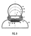
- a filter 36 is situated in a box 37 which is open at the bottom and the top and which is secured to the holder 1.
- An opening 38 at the top of the box is provided with a first flexible valve 39.
- the device operates as follows: When the upper housing section 34 is pressed down the elastic lower housing section 33 is depressed, which reduces the volume of the first reservoir. The rinsing liquid is thus pressurised and is forced up through the filter 36.
- the first flexible valve 39 then opens, whereas the second flexible valve 42 for the openings along the box periphery is closed.
- the rinsing liquid flows past and through the object to be cleaned and pushes the flexible diaphragm 35 upward, as is shown in broken lines in Fig. 8.
- the space underneath the diaphragm 35 forms the second reservoir.
- the first valve 39 is then closed and the second valve 42 at the periphery of the box 37 is opened.
- the liquid with contaminants finds its way to the lower reservoir. Upon the next depression stroke the contaminants are caught in the filter 36.
- the filter is ring-shaped and is also arranged in a box-shaped structure.
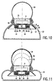
- a central wall portion 43 of the filter box 37 has openings 38, which can be opened or closed by a common first flexible valve 39 and at the location of the ring-shaped filter 36 a wall portion 44 of the filter box 37 has openings 41, which can be opened or closed by a common second flexible valve 42.
- the valve 39 is opened and the valve 42 is closed (see Fig. 11).
- the valve 39 is closed, thereby forcing the liquid with the contaminants through the filter, the valve 42 then being opened (see Fig. 12).
- the objects are always rinsed with a comparatively clean liquid, which promotes the cleaning action.
- a bell-shaped wall portion 45 has been provided in the lower reservoir in order to create an air space 46.
- the filter 36 is disposed in this air space. In this way it is achieved that air is entrained by the circulating liquid, resulting in a more turbulent flow.
- an air space is formed automatically as a result of the bell-shaped structure.
- the edge 47 of the bell-shaped wall portion 45 should then project from underneath the filter box 37.
- the turbulence can be further increased by the use of a plate 48 with a multitude of apertures 49. This plate is arranged in the passage 8 to the lower reservoir, right underneath the object 4.
- Perforate objects can thus be cleaned very well. However, cleaning is also possible when the objects are imperforate.
- the walls of the opening 2 of the holder 1 may be provided with, for example, projections between which recesses are formed to allow the passage of the liquid.
Landscapes
- Cleaning By Liquid Or Steam (AREA)
- Filling Of Jars Or Cans And Processes For Cleaning And Sealing Jars (AREA)
- Cleaning In General (AREA)
Abstract
Description
The device operates as follows: After the
Claims (3)
- A device for rinsing objects comprising at least two reservoirs for holding rinsing liquid, a first depressible housing section (33) forming a first reservoir with a variable volume, a second housing section (34) having a second reservoir, a holder (1) for supporting an object (4) to be cleaned, said rinsing being obtained by pumping liquid from the first reservoir to the second reservoir, a filter (36) for retaining contaminants from the liquid and valve means (39,42) effective to control the direction of passage of the liquid through the filter during rinsing, characterised in that said filter (36) is contained in a walled box (37) with multiple openings (38,41), a first opening (38) being provided with a first valve (39) and a second opening (41) being provided with a second valve (42) which is closed when the first valve is open and open when the first valve is closed, the first valve being open when the first housing section (33) is depressed.
- A device as claimed in claim 1, characterised in that the first housing section (33) has at least an elastically depressible wall.
- A device as claimed in claim 1 or 2, characterised in that the second housing section (34) comprises a flexible diaphragm (35) forming a wall of the second reservoir.
Priority Applications (1)
| Application Number | Priority Date | Filing Date | Title |
|---|---|---|---|
| EP95938000A EP0743883B1 (en) | 1994-12-12 | 1995-12-06 | Device for rinsing objects |
Applications Claiming Priority (4)
| Application Number | Priority Date | Filing Date | Title |
|---|---|---|---|
| EP94203597 | 1994-12-12 | ||
| EP94203597 | 1994-12-12 | ||
| PCT/IB1995/001098 WO1996018463A1 (en) | 1994-12-12 | 1995-12-06 | Device for rinsing objects |
| EP95938000A EP0743883B1 (en) | 1994-12-12 | 1995-12-06 | Device for rinsing objects |
Publications (2)
| Publication Number | Publication Date |
|---|---|
| EP0743883A1 EP0743883A1 (en) | 1996-11-27 |
| EP0743883B1 true EP0743883B1 (en) | 1999-06-30 |
Family
ID=8217446
Family Applications (1)
| Application Number | Title | Priority Date | Filing Date |
|---|---|---|---|
| EP95938000A Expired - Lifetime EP0743883B1 (en) | 1994-12-12 | 1995-12-06 | Device for rinsing objects |
Country Status (6)
| Country | Link |
|---|---|
| US (1) | US5839457A (en) |
| EP (1) | EP0743883B1 (en) |
| JP (1) | JP3929488B2 (en) |
| CN (1) | CN1090544C (en) |
| DE (1) | DE69510534T2 (en) |
| WO (1) | WO1996018463A1 (en) |
Cited By (2)
| Publication number | Priority date | Publication date | Assignee | Title |
|---|---|---|---|---|
| US7107692B2 (en) * | 2003-04-04 | 2006-09-19 | Braun Gmbh | Cleaning device for a shaving apparatus |
| RU2308862C2 (en) * | 2003-04-04 | 2007-10-27 | БРАУН ГмбХ | Cleaning device for electromechanical shaver |
Families Citing this family (24)
| Publication number | Priority date | Publication date | Assignee | Title |
|---|---|---|---|---|
| US5711921A (en) * | 1996-01-02 | 1998-01-27 | Kew Import/Export Inc. | Medical cleaning and sterilizing apparatus |
| DE19705975C2 (en) * | 1997-02-17 | 2000-03-30 | Braun Gmbh | Cleaning device for a dry shaver |
| DE19705977C1 (en) * | 1997-02-17 | 1998-03-05 | Braun Ag | Cleaner for cutting head of dry razor |
| US6125866A (en) * | 1998-11-10 | 2000-10-03 | Philip Morris Incorporated | Pump cleaning unit for the heater fixture of a smoking device |
| US5947137A (en) * | 1998-11-18 | 1999-09-07 | Sheafer; Tim | Draw-tube solvent retaining and draining cover |
| US6343612B1 (en) * | 1999-01-14 | 2002-02-05 | Carla Cherry Dahl | Portable pacifier cleaner and container |
| DE19937166A1 (en) * | 1999-08-06 | 2001-03-01 | Braun Gmbh | Cleaning device for a shaver |
| DE10039254C1 (en) * | 2000-08-11 | 2002-01-03 | Olaf Freise | Cleaning container, for spectacles, has cap and has bellows arranged at base, to clamp spectacles between cap and bellows, which is held in container by several inward projections |
| DE10315455A1 (en) | 2003-04-04 | 2004-11-11 | Braun Gmbh | Cleaning device for a shaver |
| DE10315451A1 (en) * | 2003-04-04 | 2004-11-04 | Braun Gmbh | Manually operated cleaning device for the shaving head of an electric shaver |
| DE102006005018B4 (en) * | 2006-02-03 | 2007-11-22 | Robert Sporer | Hub-sea diving |
| DE102006039715A1 (en) * | 2006-08-24 | 2008-02-28 | Dürr Ecoclean GmbH | Cleaning device with a flood chamber |
| WO2008075243A1 (en) * | 2006-12-15 | 2008-06-26 | Koninklijke Philips Electronics N.V. | Unit for cleaning an interior space of a shaving head of a shaver |
| DE102007001183A1 (en) * | 2007-01-05 | 2008-08-21 | Cornelius Doniga | Device for storing contact lenses has two containers for accommodating contact lenses, where containers are closed by cover |
| FR2921846B1 (en) * | 2007-10-09 | 2011-04-22 | Soprodic | FILTER ELEMENT FOR DEVICE FOR CLEANING OBJECTS, AND DEVICE FOR CLEANING OBJECTS |
| DE202008002794U1 (en) * | 2008-02-27 | 2008-05-15 | Doniga, Cornelius | Contact lens container with compression lid |
| CN201419170Y (en) * | 2009-03-18 | 2010-03-10 | 鸿富锦精密工业(深圳)有限公司 | Nozzle cleaning device |
| JP2011140007A (en) | 2010-01-08 | 2011-07-21 | Omron Healthcare Co Ltd | Thin sheet member washing apparatus |
| AU2012267214B2 (en) * | 2011-06-09 | 2016-11-03 | Anthony SILJEG | Device for cleaning a teat |
| CN104224082A (en) * | 2014-10-14 | 2014-12-24 | 倪邦勇 | Portable chopstick cleaner |
| CN104441288B (en) * | 2014-10-31 | 2016-08-31 | 镇江环太硅科技有限公司 | A kind of solar silicon wafers processing cutting equipment and method |
| CN105818294B (en) * | 2016-04-29 | 2018-04-17 | 江汉大学 | A kind of cleaning device |
| CN108787554B (en) * | 2017-05-04 | 2024-01-05 | 苏州宝时得电动工具有限公司 | Hand-held high-pressure cleaning machine |
| DE102018126437B4 (en) * | 2018-10-24 | 2024-04-11 | Optik-Elektro Huber GmbH | Cleaning station; Plant for producing a component; Method for cleaning a component; Method for producing a component |
Family Cites Families (9)
| Publication number | Priority date | Publication date | Assignee | Title |
|---|---|---|---|---|
| US1421971A (en) * | 1922-07-04 | Beet mccarty | ||
| AT182095B (en) * | 1952-10-30 | 1955-05-25 | Eryk Artur Kollontay | Washing device |
| US3066687A (en) * | 1961-09-01 | 1962-12-04 | Henry G Rohmann | Jewelry washer |
| US3512539A (en) * | 1968-07-08 | 1970-05-19 | Arthur R Hamilton | Washer having reciprocating work basket |
| US3762426A (en) * | 1972-04-26 | 1973-10-02 | Ibm | Semiconductor chip separation apparatus |
| SU648291A1 (en) * | 1977-04-18 | 1979-02-25 | Предприятие П/Я Р-6930 | Article-washing device |
| US4721124A (en) * | 1983-12-01 | 1988-01-26 | Barry Tuerkheimer | Optometric soft and rigid contact lens cleaning and storage system |
| SU1201003A1 (en) * | 1984-03-23 | 1985-12-30 | Куйбышевский институт инженеров железнодорожного транспорта | Installation for washing articles |
| US4700729A (en) * | 1985-11-12 | 1987-10-20 | Windmere Corporation | Lens cleaning device |
-
1995
- 1995-12-06 WO PCT/IB1995/001098 patent/WO1996018463A1/en not_active Ceased
- 1995-12-06 CN CN95192381A patent/CN1090544C/en not_active Expired - Fee Related
- 1995-12-06 DE DE69510534T patent/DE69510534T2/en not_active Expired - Fee Related
- 1995-12-06 EP EP95938000A patent/EP0743883B1/en not_active Expired - Lifetime
- 1995-12-06 JP JP51853496A patent/JP3929488B2/en not_active Expired - Fee Related
-
1997
- 1997-06-25 US US08/882,441 patent/US5839457A/en not_active Expired - Fee Related
Cited By (2)
| Publication number | Priority date | Publication date | Assignee | Title |
|---|---|---|---|---|
| US7107692B2 (en) * | 2003-04-04 | 2006-09-19 | Braun Gmbh | Cleaning device for a shaving apparatus |
| RU2308862C2 (en) * | 2003-04-04 | 2007-10-27 | БРАУН ГмбХ | Cleaning device for electromechanical shaver |
Also Published As
| Publication number | Publication date |
|---|---|
| JPH09509364A (en) | 1997-09-22 |
| DE69510534D1 (en) | 1999-08-05 |
| JP3929488B2 (en) | 2007-06-13 |
| DE69510534T2 (en) | 2000-02-17 |
| CN1145041A (en) | 1997-03-12 |
| WO1996018463A1 (en) | 1996-06-20 |
| EP0743883A1 (en) | 1996-11-27 |
| CN1090544C (en) | 2002-09-11 |
| US5839457A (en) | 1998-11-24 |
Similar Documents
| Publication | Publication Date | Title |
|---|---|---|
| US5839457A (en) | Device for rinsing objects | |
| US6394315B1 (en) | Squeeze operated foam dispenser | |
| KR100777364B1 (en) | Air pump type discharge device and container for household goods including the same | |
| US7437795B1 (en) | Mop bucket assembly | |
| GB2171166A (en) | Parts cleaner | |
| US7004659B1 (en) | Method and apparatus for dispensing solution on toilet paper | |
| GB2136059A (en) | A cream-state fluid dispensing container | |
| KR960015981B1 (en) | Liquid detergent dispenser in the washing machine | |
| CN116323405B (en) | Containers for spraying liquids | |
| JP4772419B2 (en) | Liquid ejection device | |
| JP5209638B2 (en) | A unit for cleaning the interior space of a shaver shaving head | |
| KR101038011B1 (en) | Pumps for Liquid Storage Containers | |
| JP2005519205A (en) | Textile local area cleaning equipment | |
| KR200481587Y1 (en) | Compressior for Toilet Stool | |
| KR200428943Y1 (en) | dispenser | |
| KR100559480B1 (en) | Constant amount liquid discharge device | |
| JP2003112708A (en) | Liquid filling nozzle | |
| KR102411886B1 (en) | Pump container | |
| KR200186695Y1 (en) | A water tank | |
| KR200423196Y1 (en) | Liquid dispenser | |
| JPS58216587A (en) | Vessel filler | |
| JP6714861B2 (en) | Soap liquid supply device | |
| CN215777876U (en) | Mop bucket with water pumping device | |
| CN215777872U (en) | Water spray cleaning device | |
| CN215777871U (en) | Water spray cleaning device |
Legal Events
| Date | Code | Title | Description |
|---|---|---|---|
| PUAI | Public reference made under article 153(3) epc to a published international application that has entered the european phase |
Free format text: ORIGINAL CODE: 0009012 |
|
| AK | Designated contracting states |
Kind code of ref document: A1 Designated state(s): DE ES FR GB IT NL |
|
| 17P | Request for examination filed |
Effective date: 19961220 |
|
| 17Q | First examination report despatched |
Effective date: 19970902 |
|
| GRAG | Despatch of communication of intention to grant |
Free format text: ORIGINAL CODE: EPIDOS AGRA |
|
| GRAG | Despatch of communication of intention to grant |
Free format text: ORIGINAL CODE: EPIDOS AGRA |
|
| GRAH | Despatch of communication of intention to grant a patent |
Free format text: ORIGINAL CODE: EPIDOS IGRA |
|
| GRAH | Despatch of communication of intention to grant a patent |
Free format text: ORIGINAL CODE: EPIDOS IGRA |
|
| GRAA | (expected) grant |
Free format text: ORIGINAL CODE: 0009210 |
|
| AK | Designated contracting states |
Kind code of ref document: B1 Designated state(s): DE ES FR GB IT NL |
|
| PG25 | Lapsed in a contracting state [announced via postgrant information from national office to epo] |
Ref country code: NL Free format text: LAPSE BECAUSE OF FAILURE TO SUBMIT A TRANSLATION OF THE DESCRIPTION OR TO PAY THE FEE WITHIN THE PRESCRIBED TIME-LIMIT Effective date: 19990630 Ref country code: IT Free format text: LAPSE BECAUSE OF FAILURE TO SUBMIT A TRANSLATION OF THE DESCRIPTION OR TO PAY THE FEE WITHIN THE PRE;WARNING: LAPSES OF ITALIAN PATENTS WITH EFFECTIVE DATE BEFORE 2007 MAY HAVE OCCURRED AT ANY TIME BEFORE 2007. THE CORRECT EFFECTIVE DATE MAY BE DIFFERENT FROM THE ONE RECORDED.SCRIBED TIME-LIMIT Effective date: 19990630 Ref country code: ES Free format text: THE PATENT HAS BEEN ANNULLED BY A DECISION OF A NATIONAL AUTHORITY Effective date: 19990630 |
|
| REF | Corresponds to: |
Ref document number: 69510534 Country of ref document: DE Date of ref document: 19990805 |
|
| ET | Fr: translation filed | ||
| NLV1 | Nl: lapsed or annulled due to failure to fulfill the requirements of art. 29p and 29m of the patents act | ||
| PLBE | No opposition filed within time limit |
Free format text: ORIGINAL CODE: 0009261 |
|
| STAA | Information on the status of an ep patent application or granted ep patent |
Free format text: STATUS: NO OPPOSITION FILED WITHIN TIME LIMIT |
|
| 26N | No opposition filed | ||
| REG | Reference to a national code |
Ref country code: GB Ref legal event code: IF02 |
|
| PGFP | Annual fee paid to national office [announced via postgrant information from national office to epo] |
Ref country code: GB Payment date: 20061218 Year of fee payment: 12 |
|
| PGFP | Annual fee paid to national office [announced via postgrant information from national office to epo] |
Ref country code: DE Payment date: 20070208 Year of fee payment: 12 |
|
| PGFP | Annual fee paid to national office [announced via postgrant information from national office to epo] |
Ref country code: FR Payment date: 20061227 Year of fee payment: 12 |
|
| GBPC | Gb: european patent ceased through non-payment of renewal fee |
Effective date: 20071206 |
|
| PG25 | Lapsed in a contracting state [announced via postgrant information from national office to epo] |
Ref country code: DE Free format text: LAPSE BECAUSE OF NON-PAYMENT OF DUE FEES Effective date: 20080701 |
|
| REG | Reference to a national code |
Ref country code: FR Ref legal event code: ST Effective date: 20081020 |
|
| PG25 | Lapsed in a contracting state [announced via postgrant information from national office to epo] |
Ref country code: GB Free format text: LAPSE BECAUSE OF NON-PAYMENT OF DUE FEES Effective date: 20071206 |
|
| PG25 | Lapsed in a contracting state [announced via postgrant information from national office to epo] |
Ref country code: FR Free format text: LAPSE BECAUSE OF NON-PAYMENT OF DUE FEES Effective date: 20071231 |