EP0744631A1 - A body sensing device - Google Patents
A body sensing device Download PDFInfo
- Publication number
- EP0744631A1 EP0744631A1 EP96108269A EP96108269A EP0744631A1 EP 0744631 A1 EP0744631 A1 EP 0744631A1 EP 96108269 A EP96108269 A EP 96108269A EP 96108269 A EP96108269 A EP 96108269A EP 0744631 A1 EP0744631 A1 EP 0744631A1
- Authority
- EP
- European Patent Office
- Prior art keywords
- coil
- sensing device
- living body
- oscillator
- frequency
- Prior art date
- Legal status (The legal status is an assumption and is not a legal conclusion. Google has not performed a legal analysis and makes no representation as to the accuracy of the status listed.)
- Granted
Links
- 238000001514 detection method Methods 0.000 claims abstract description 40
- 230000010355 oscillation Effects 0.000 claims abstract description 34
- 229910052755 nonmetal Inorganic materials 0.000 claims description 8
- 230000008859 change Effects 0.000 claims description 7
- 230000035945 sensitivity Effects 0.000 claims description 5
- 230000003321 amplification Effects 0.000 claims description 4
- 239000004020 conductor Substances 0.000 claims description 4
- 238000003199 nucleic acid amplification method Methods 0.000 claims description 4
- 230000004044 response Effects 0.000 claims description 4
- 239000000126 substance Substances 0.000 abstract description 8
- 239000003990 capacitor Substances 0.000 description 18
- 238000010586 diagram Methods 0.000 description 17
- 229910052751 metal Inorganic materials 0.000 description 14
- 239000002184 metal Substances 0.000 description 14
- 230000005540 biological transmission Effects 0.000 description 8
- 230000004048 modification Effects 0.000 description 8
- 238000012986 modification Methods 0.000 description 8
- 239000010949 copper Substances 0.000 description 4
- 239000010931 gold Substances 0.000 description 4
- 230000035699 permeability Effects 0.000 description 4
- 238000006073 displacement reaction Methods 0.000 description 3
- RYGMFSIKBFXOCR-UHFFFAOYSA-N Copper Chemical compound [Cu] RYGMFSIKBFXOCR-UHFFFAOYSA-N 0.000 description 2
- 229910052782 aluminium Inorganic materials 0.000 description 2
- XAGFODPZIPBFFR-UHFFFAOYSA-N aluminium Chemical compound [Al] XAGFODPZIPBFFR-UHFFFAOYSA-N 0.000 description 2
- 229910052802 copper Inorganic materials 0.000 description 2
- 230000008878 coupling Effects 0.000 description 2
- 238000010168 coupling process Methods 0.000 description 2
- 238000005859 coupling reaction Methods 0.000 description 2
- 230000003247 decreasing effect Effects 0.000 description 2
- PCHJSUWPFVWCPO-UHFFFAOYSA-N gold Chemical compound [Au] PCHJSUWPFVWCPO-UHFFFAOYSA-N 0.000 description 2
- 229910052737 gold Inorganic materials 0.000 description 2
- 239000000463 material Substances 0.000 description 2
- 229910052709 silver Inorganic materials 0.000 description 2
- 239000004332 silver Substances 0.000 description 2
- 239000012141 concentrate Substances 0.000 description 1
- 238000010276 construction Methods 0.000 description 1
- 239000013078 crystal Substances 0.000 description 1
- 230000007246 mechanism Effects 0.000 description 1
- 238000000034 method Methods 0.000 description 1
- 230000010363 phase shift Effects 0.000 description 1
- 230000008569 process Effects 0.000 description 1
- ZMRUPTIKESYGQW-UHFFFAOYSA-N propranolol hydrochloride Chemical compound [H+].[Cl-].C1=CC=C2C(OCC(O)CNC(C)C)=CC=CC2=C1 ZMRUPTIKESYGQW-UHFFFAOYSA-N 0.000 description 1
- 230000009467 reduction Effects 0.000 description 1
- 230000000087 stabilizing effect Effects 0.000 description 1
Images








Classifications
-
- G—PHYSICS
- G01—MEASURING; TESTING
- G01V—GEOPHYSICS; GRAVITATIONAL MEASUREMENTS; DETECTING MASSES OR OBJECTS; TAGS
- G01V3/00—Electric or magnetic prospecting or detecting; Measuring magnetic field characteristics of the earth, e.g. declination, deviation
- G01V3/15—Electric or magnetic prospecting or detecting; Measuring magnetic field characteristics of the earth, e.g. declination, deviation specially adapted for use during transport, e.g. by a person, vehicle or boat
-
- G—PHYSICS
- G01—MEASURING; TESTING
- G01V—GEOPHYSICS; GRAVITATIONAL MEASUREMENTS; DETECTING MASSES OR OBJECTS; TAGS
- G01V3/00—Electric or magnetic prospecting or detecting; Measuring magnetic field characteristics of the earth, e.g. declination, deviation
- G01V3/08—Electric or magnetic prospecting or detecting; Measuring magnetic field characteristics of the earth, e.g. declination, deviation operating with magnetic or electric fields produced or modified by objects or geological structures or by detecting devices
- G01V3/10—Electric or magnetic prospecting or detecting; Measuring magnetic field characteristics of the earth, e.g. declination, deviation operating with magnetic or electric fields produced or modified by objects or geological structures or by detecting devices using induction coils
- G01V3/101—Electric or magnetic prospecting or detecting; Measuring magnetic field characteristics of the earth, e.g. declination, deviation operating with magnetic or electric fields produced or modified by objects or geological structures or by detecting devices using induction coils by measuring the impedance of the search coil; by measuring features of a resonant circuit comprising the search coil
- G01V3/102—Electric or magnetic prospecting or detecting; Measuring magnetic field characteristics of the earth, e.g. declination, deviation operating with magnetic or electric fields produced or modified by objects or geological structures or by detecting devices using induction coils by measuring the impedance of the search coil; by measuring features of a resonant circuit comprising the search coil by measuring amplitude
-
- G—PHYSICS
- G01—MEASURING; TESTING
- G01D—MEASURING NOT SPECIALLY ADAPTED FOR A SPECIFIC VARIABLE; ARRANGEMENTS FOR MEASURING TWO OR MORE VARIABLES NOT COVERED IN A SINGLE OTHER SUBCLASS; TARIFF METERING APPARATUS; MEASURING OR TESTING NOT OTHERWISE PROVIDED FOR
- G01D5/00—Mechanical means for transferring the output of a sensing member; Means for converting the output of a sensing member to another variable where the form or nature of the sensing member does not constrain the means for converting; Transducers not specially adapted for a specific variable
- G01D5/12—Mechanical means for transferring the output of a sensing member; Means for converting the output of a sensing member to another variable where the form or nature of the sensing member does not constrain the means for converting; Transducers not specially adapted for a specific variable using electric or magnetic means
- G01D5/14—Mechanical means for transferring the output of a sensing member; Means for converting the output of a sensing member to another variable where the form or nature of the sensing member does not constrain the means for converting; Transducers not specially adapted for a specific variable using electric or magnetic means influencing the magnitude of a current or voltage
- G01D5/20—Mechanical means for transferring the output of a sensing member; Means for converting the output of a sensing member to another variable where the form or nature of the sensing member does not constrain the means for converting; Transducers not specially adapted for a specific variable using electric or magnetic means influencing the magnitude of a current or voltage by varying inductance, e.g. by a movable armature
-
- G—PHYSICS
- G01—MEASURING; TESTING
- G01R—MEASURING ELECTRIC VARIABLES; MEASURING MAGNETIC VARIABLES
- G01R27/00—Arrangements for measuring resistance, reactance, impedance, or electric characteristics derived therefrom
- G01R27/02—Measuring real or complex resistance, reactance, impedance, or other two-pole characteristics derived therefrom, e.g. time constant
-
- H—ELECTRICITY
- H03—ELECTRONIC CIRCUITRY
- H03K—PULSE TECHNIQUE
- H03K17/00—Electronic switching or gating, i.e. not by contact-making and –breaking
- H03K17/94—Electronic switching or gating, i.e. not by contact-making and –breaking characterised by the way in which the control signals are generated
- H03K17/945—Proximity switches
- H03K17/95—Proximity switches using a magnetic detector
- H03K17/952—Proximity switches using a magnetic detector using inductive coils
- H03K17/9537—Proximity switches using a magnetic detector using inductive coils in a resonant circuit
- H03K17/954—Proximity switches using a magnetic detector using inductive coils in a resonant circuit controlled by an oscillatory signal
-
- H—ELECTRICITY
- H03—ELECTRONIC CIRCUITRY
- H03K—PULSE TECHNIQUE
- H03K17/00—Electronic switching or gating, i.e. not by contact-making and –breaking
- H03K17/94—Electronic switching or gating, i.e. not by contact-making and –breaking characterised by the way in which the control signals are generated
- H03K17/945—Proximity switches
- H03K17/95—Proximity switches using a magnetic detector
- H03K17/952—Proximity switches using a magnetic detector using inductive coils
- H03K17/9537—Proximity switches using a magnetic detector using inductive coils in a resonant circuit
- H03K17/9542—Proximity switches using a magnetic detector using inductive coils in a resonant circuit forming part of an oscillator
- H03K17/9547—Proximity switches using a magnetic detector using inductive coils in a resonant circuit forming part of an oscillator with variable amplitude
Definitions
- This invention relates to a body sensing device for sensing the presence or absence of a body, and more particularly to an improved living body sensing device capable of sensing the seating of a living body.
- Conventional sensing devices for sensing the presence or absence of a living body are a weight sensor for measuring the weight, an electrostatic capacity sensor utilizing an electrostatic capacity varying with the approach of the living body, a photo sensor for detecting the reflection or interruption by the living body, an infrared sensor, and an ultrasonic sensor.
- the above-mentioned conventional sensors cannot discriminate the living body at a standstill from a piece of baggage.
- the weight sensor erroneously identifies heavy baggage seated on the sensor as a living body.
- the photo sensor erroneously identifies the presence of any object whenever light is interrupted by any material.
- the ultrasonic sensor erroneously identifies the presence of an object whenever the ultrasonic wave is reflected by any material.
- the infrared sensor has the disadvantage that the living body at a standstill is ignored.
- An electrostatic capacitive sensor installed in a floor is conventionally used, but sensible to external conditions. If a foot separates from the floor, the sensor is erroneously operated. If a child sitting on a chair does not reach the floor, the child cannot be detected.
- a body sensing device including an oscillator for stopping the oscillation of a high frequency signal when a body to be detected thereby exists near a coil, and a controller for detecting the stop of the oscillation of the oscillator, the high frequency signal having such a frequency that the oscillator stops its oscillation in response to the approach by a non-magnetic body or a non-metallic body.
- the oscillator oscillates when no substance exists, but stops its oscillation when a non-magnetic body or a non-metal body exists near the device.
- the high frequency signal of the oscillator is designed to be between 10 MHz and 300 MHz.
- the coil is the size fitting to the body to be detected by the device, and employs an air-core coil having at least one turn.
- the coil may be modified to be wound around a magnetic member, and a plurality of coils connected one another.
- a living body sensing device including a coil for sensing a living body, a discriminating circuit connected with the coil for discriminating the approach of the living body, a circuit housing enclosing the discriminating circuit, in which the size of the coil in any horizontal directions is larger than that of the circuit housing in any horizontal directions.
- the coil is one-turn coil fitting to a portion of the body in size, and particularly a circular air-core coil having a diameter between 15 centimeters and 30 centimeters.
- the coil is built within a seat or a cushion.
- the coil is made of good conductive materials in a high frequency.
- the discriminating circuit includes an oscillator for stopping its oscillation of a high frequency signal when a living body to be detected thereby exists near a coil, and a controller for detecting the stop of the oscillation of the oscillator.
- the oscillator is provided with a sensitivity adjuster for changing a quality factor of the coil.
- the oscillator also may be provided with a temperature compensation circuit for compensating the change of the level or frequency of the high frequency signal by temperatures.
- a living body sensing device comprising an oscillator for generating a high frequency signal having a different level depending whether or not a living body exists near a coil, a detector for detecting an output signal generated from the oscillator, and a controller for discriminating the existence or absence of the living body in accordance with the magnitude of an output signal generated from the detector.
- the living body sensing device further includes a series circuit of a filter and an amplifier which is connected with the detector in parallel, in which any signal having a frequency higher than that of the high frequency signal upon the existence and absence of the living body near the coil is detected by the filter to be amplified by the amplifier and the level of the output signal generated from the detector is compensated by an output from the amplifier.
- the device may alternatively include an amplifier interposed between the detector and the controller and frequency detecting means for detecting the frequency of the output signal from the detector, in which an amplification factor of the amplifier is changed according to the frequency detected by the frequency detecting means.
- a living body sensing device including an oscillator for generating a high frequency signal having a different level depending whether or not a living body exists near a coil, a detector for detecting an output signal generated from the oscillator to generate a detection signal, a controller for discriminating the existence or absence of the living body in accordance with the magnitude of the output signal generated from the detector, and frequency detecting means for detecting an output frequency of the oscillator, in which the controller determines the absence of the living body regardless of the level of the detection signal when the output frequency detected by the frequency detecting means is higher than the frequency upon the detection of the living body and non-detection of the living body and a body.
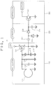
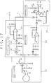
- a circuit diagram of a human body sensing device 1 as a living body sensing device which includes an oscillator 10 for oscillating a high frequency signal, a detector 20 for detecting the high frequency signal from the oscillator 10, a controller 30 for receiving a detected signal from the detector 20 to discriminate the existence or absence of a human body.
- the oscillator 10 includes a detection coil 11, a capacitor 12 connected in parallel with the detection coil 11 and its one end is grounded, a resistor 13 connected in parallel with the capacitor 11, an FET 14 at its gate connected with one ends of these parallel connections, a series circuit of capacitors 15 and 16 connected between the gate of the FET 14 and the ground, and a resistor 17 connected in parallel with the capacitor 16.
- a connection point of the capacitors 15 and 16 is connected with a drain of the FET 14, and a source of the FET 14 is connected with a power source Vcc.
- the oscillator 10 employs a conventional Colpitts type LC oscillator. If desired, other oscillator such as a Hartley oscillator may be employed.
- the oscillation frequency of the oscillator 10 is desirable to be 10 MHz or higher.
- a diameter of a wire of the coil is 1.2 mm and a diameter of the coil is 200 mm. If desired, the diameter of the coil 11 may be between 150 mm and 300 mm.
- the capacitor 12 is 27 PF.
- the resistor 13 may be a variable resistor having a range from 10 K ⁇ to 150 K ⁇ for sensitivity adjustment so that the best sensitivity can be set to a human body existence.
- the capacitors 15 and 16 are respectively 47 PF.
- the resistor 17 is 470 ⁇ . These factors are one example, and may be changed according to a frequency for oscillation.
- the detector 20 includes a capacitor 21 at one end thereof connected to the drain of the FET 14, a diode 22 at a cathode thereof connected with another end of the capacitor 21 and an anode thereof grounded, a diode 23 at an anode thereof connected with the another end, a capacitor 24 connected between a cathode of the diode 23 and the ground to generate a detection signal from a cathode of the diode 23.
- the controller 30 includes an NPN-type transistor 31 at a base thereof for receiving the output signal from the detector 20, at an emitter thereof grounded and at a collector thereof for generating a signal representing the presence or absence of a human body.
- the detection coil 11 is a circular one-turn air-core coil having a diameter of 200 mm.
- the oscillator 10 other than the coil 11, the detector 20 and the controller 30 are housed within a circuit housing 40.
- the detection coil 11 may be modified to have a coil 11a having a diameter 200 mm and a coil 11b having a diameter 100 mm which are selectively used or connected in series as shown in Fig. 3, whereby diameters of the coils can be reduced in size.
- the detection coil 11 may be wound around a magnetic core 18 as shown in Fig. 4 so that a magnetic field can be generated only in one direction lying at right angles to a wall of the coil 11.
- the conductive wire of the detection coil 11 employs a good conductive materials about a high frequency signal, such as Au (gold), Ag (silver), Cu (copper), Al (aluminum) and so forth.
- a compact detection coil capable of generating many magnetic line of force to concentrate energy forward and of efficiently catching a change of permeability and displacement current.
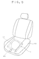
- the human body sensing device 1 of this embodiment may be buried within a bottom of a seat (in an automobile, a train, a theater and so forth) 51 as shown in Fig. 5 or within a seat cushion 52 as shown in Fig. 6.
- the device may be buried within other portions of a seat such as a support for the back of the seat.
- the cushion 52 enclosing the device is portable and it is useful for a driver to confirm the absence of a child on a rear seat in a car when the cushion is put on the rear seat.
- the quality factor Q of the detection coil 11 is high and the oscillator 10 oscillates a high frequency signal (10MHz).
- the high frequency signal generated from the oscillator 10 is detected by the detector 20 to be applied to the transistor 31, wherein an input level in the transistor 31 is high and the transistor is turned ON. This ON signal is outputed as a signal representing the absence of any human body.
- the quality factor Q of the detection coil is reduced by the influence of permeability in the human body and the oscillator 10 stops its oscillation. Accordingly, the level of the high frequency signal applied to the detector 20 is also reduced to "0" and the detection signal from the detector 20 is low to turn OFF the transistor 31. This OFF signal is outputed as a signal representing the existence of the human body.
- the controller 30 outputs the signal representing the existence and absence of a human body.
- an operation display unit consisting of a resistor 32 and a light emitting diode 33 may be interposed between a collector of the transistor 31 of the controller 30 and the source voltage Vcc.
- an electric current flows the resistor 32 and the light emitting diode 33 to light the diode 33.
- the oscillator 10 stops its oscillation, the transistor 31 is turned OFF, and the diode 33 is also turned off.
- a human body including a child at standstill can be precisely discriminated from baggage without contacting the human body and without influence by clothes of the human body and weight.
- Fig. 10 is a schematic circuit diagram of a human body sensing device 1 as a second embodiment of this invention, which includes an oscillator 10, a detector 20 and a controller 30.
- the oscillator 10 and the detector 20 have the same construction as those of the device 1 of Fig. 1.
- the controller 30 of Fig. 10 includes a comparator 34 and a reference voltage setting unit 35, which is different from the device 1 of Fig. 1.
- the comparator 34 compares the detection signal from the detector 20 with a reference voltage determined by the reference voltage setting unit 35 to generate a signal representing the absence of a human body when the detection signal is higher than the reference voltage and to generate a signal representing the existence of a human body when the detection sinal is lower than the reference voltage.
- the resistor 13 of Figs. 1 and 10 may be modified to be a variable resistor a resistance value of which is varied with temperature sensed by a temperature sensor installed in the circuit housing 40 or the seat 51 or the like so that the change of oscillation magnitude and frequency caused by the change of ambient temperature is reduced. If desired, temperature compensation may be employed by installing a temperature compensation element such as a thermistor into the oscillator 10.
- Fig. 11 is a schematic circuit diagram of a human body sensing device 1 as a third embodiment of this invention, which includes a sensor 60, an oscillator 80 for transmitting a high frequency signal to the sensor 60 through a transmission path 70, a reflected wave sensor 90 detecting a reflection signal of the high frequency signal applied to the sensor 60 to be reflected by the same, and a controller 100 receiving the detected reflection signal for processing.
- the sensor 60 includes a detection coil 61, a resonance capacitor 62 forming a series resonance circuit with the detection coil 61, and a real number transformer 63 in which a primary coil thereof is connected with the resonance circuit in an input side and a secondary coil thereof is connected with a high frequency input terminal 64 and a ground.
- the resonance circuit may employ a parallel resonance circuit if desired.
- the detection coil 61 may employ anyone of the coils of Figs. 2, 3 and 4 and be installed in the seat or cushion of Fig. 5 or 6.
- the conductive wire of the detection coil 61 employs a good conductive materials about a high frequency signal, such as Au (gold), Ag (silver), Cu (copper), Al (aluminum) and so forth.
- a good conductive materials about a high frequency signal such as Au (gold), Ag (silver), Cu (copper), Al (aluminum) and so forth.
- the good conductivity of the coil 61 provides an improved sensitivity and a reduction of a high frequency power loss.
- the oscillator 80 employs an oscillation circuit of a LC resonance type, but may employ any conventional high frequency oscillation circuit, such as a crystal oscillator or a phase locked loop (PLL).
- the oscillator 80 includes a variable capacitor 81, in which the frequency of the high frequency signal generated from the oscillator 80 is scanned between 30MHz and 50MHz by automatically changing the capacity of the variable capacitor 81.
- a scanning mechanism for such scanning may be disposed in the oscillator 80, and changed by an instruction produced from the controller 100.
- the reflected wave sensor 90 includes a capacitor 91 connected with the transmission path 70 and a parallel circuit consisting of a resistor 92 and a coil 93 M-coupled with the transmission path 70.
- the parallel circuit at one end thereof is connected with the capacitor 31 and at another end thereof is connected with an anode of a diode 94.
- a cathode of the diode 94 is grounded through a capacitor 95 and externally generates an analog output signal.
- the reflected wave sensor 90 employs thus CM coupling, but may employ an MM coupling or other sensor if desired.
- a capacitor 96 is disposed to divide the signal from the sensor 60 for output, but may be omitted if desired. If so omitted, the signal is directly applied to the parallel circuit of the resistor 92 and the coil 93 through the capacitor 91.
- the controller 100 includes an A/D converter 101 for converting an analog signal from the reflected wave sensor 90 into a digital signal, and a CPU 102 for logically processing the digital signal about the reflection wave level and frequency to execute a discrimination process such as vacancy, baggage, and the seating of a human body.
- the human body sensing device 1 of this embodiment is buried within a bottom of a seat (in an automobile, a train, a theater and so forth) 51 as shown in Fig. 5 or within a seat cushion 52 as shown in Fig. 6.
- the device may be buried within other portions of the seat such as a support for the back of the seat.
- the oscillator 80 oscillates a high frequency signal to be applied to the sensor 60 through the transmission path 70.
- the high frequency signal of the oscillator 80 is scanned in the range from 30MHz to 50MHz.
- the high frequency signal applied to the sensor 60 is reflected by the sensor 60.
- the sensor 60 According to a substance positioned near the detection coil 61, the sensor 60 has a different impedance due to the difference of permeability or displacement current of the substance, so that the level of a reflected wave generated by a neighborhood, viz., an external circumstance differs.
- This reflected wave is detected by the reflected wave sensor 90, and the controller 100 discriminates in view of the level and the frequency of the reflected wave whether the seat is vacancy, put by baggage, or seated by a human body.
- Fig. 12 is a schematic circuit diagram of a human body sensing device 1 as a fourth embodiment of this invention.
- the device 1 includes a sensor 60 and a reflected wave sensor 90 which have same components as those of the device of Fig. 11, and a PLL oscillator 82 different from the device of Fig. 11.
- the oscillator 80 changes its high oscillation frequency in accordance with an instruction from a CPU 102 of the controller 100.
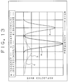
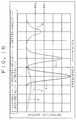
- the human body sensing device 1 of Fig. 11 or 12 is installed into the seat 51 of Fig. 5 or the cushion 52 of Fig. 6 and the oscillator 80 is activated, the characteristic of the oscillation output when the seat is vacancy, seated by a child, seated by an adult and put by baggage is shown by curves "a", "b", “c” and “d” of Fig. 13.
- the reflected wave is very small at a frequency and the quality factor "Q" is high.
- the reflected wave is small at a frequency but its change is small, and the quality factor Q is small.
- the difference of the frequency characteristic of thus reflected waves is made by the difference of the permeability and displacement current when the seat is vacancy (air), put by baggage and seated by a human body.
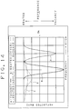
- the level of the reflected wave detected by the reflected wave sensor 13 is larger than a reference value S R over a whole frequency range as shown in Fig. 14, it means that the human body is seated. If there is a frequency where the level of a reflected wave is lower than the reference value S R , it means that the seat is vacancy or put by baggage.
- the CPU 102 of the controller 100 discriminates the human body, vacancy and baggage.
- Fig. 15 there is shown a flow chart to show a detection operation in the human body sensing device 1 of Fig. 12.
- a frequency setting counter is set to "0" (step ST1). Then a count value of the frequency setting counter is set to the PLL oscillator 82 of the oscillator 80 (step ST2). In this sate the oscillator 80 oscillates a high frequency signal of a frequency corresponding to the set value. This high frequency signal is applied to the sensor 60 through the transmission path 70, and a reflection signal according to an external state is detected by the reflected wave sensor 90. The CPU 102 reads the A/D converted value of the reflection wave through the A/D converter 101 (step ST3).
- step ST4 It is inquired if the read A/D value of the reflected wave is a reference value (75) or larger (step ST4). If the read A/D value is the reference value or larger, the frequency setting counter is increased by "1" (step ST5) and it is inquired whether or not the counted value of the frequency setting counter reaches "16" (step ST6). At first the counted value does not reach "16" and the sequence returns to the step ST2 where the counted value of the frequency setting counter increased by "1" is set to the PLL oscillator 82 and the oscillator 80 oscillates at a frequency corresponding to the new counted value. The sequence from the step ST2 to the step ST6 is repeated likewise.
- a NO response is generated at the step ST4.
- the counted value of the frequency setting counter becomes "16”
- one time scanning of frequency change is completed.
- the level of the reflected wave is the reference value S R or larger over the scanning frequency range. Accordingly, as the counted value of the frequency setting counter becomes "16" at the step ST6, an YES response is generated and the presence of the human body is judged (step ST8).
- Fig. 16 shows a circuit diagram of a human body sensing device as a fifth embodiment of this invention, which includes an attenuator 110 additionally interposed between the oscillator 80 and the reflected wave sensor 90 of Fig. 11.
- the attenuator 110 employs a ⁇ type circuit consisting of resistors 111, 112 and 113, but may employ other type of circuit.
- the signal from the reflected wave sensor 90 increases.
- the load impedance of the oscillator 80 and the input impedance of the sensor 60 are not matched and the operation of the oscillator 80 is unstable.
- the attenuator 110 is disposed at an output side of the oscillator 80 and a part of the output of the oscillator 80 is always consumed by the resistors. Even if the impedance largely varies and matching is not obtained, the oscillator 80 safely operates by stabilizing the load impedance of the oscillator 80.
- the sensing devices may be so designed that the high frequency signal generated from the oscillator is applied to the sensor through the transmission path and a phase shift against the high frequency signal transmitted in the detector from the transmission path is detected.
- the sensing device may be so designed that the high frequency signal generated in the oscillator is supplied to the sensor including a resonance circuit through a transmission path and a voltage or a current in the sensor is detected according to the external status such as vacancy, baggage, the human body or the like to detect a body.
- the human body sensing devices of the foregoing embodiments are designed to identify vacancy, baggage and the human body as a human body sensor, but may be applied to a substance sensor for sensing substances other than baggage.
- Fig. 17 is a schematic circuit diagram of a human body sensing device 1 as a sixth embodiment of this invention.
- the device 1 includes an oscillator 10, a detector 20, and a controller 30.
- the sensing devices 1 of Figs. 1 and 10 for discriminating a human body and other body is liable to erroneously detect a metal body as a human body because a metal body provides a level similar to the levels of non-metal and a human body as shown in Fig. 18.
- the human body sensing device 1 of Fig. 17 is so designed to prevent any erroneous operation about a metal plate by reviewing a frequency of an oscillation frequency about a metal body.
- the device 1 of this embodiment further includes a filter circuit 120.
- the circuit 120 includes a high frequency filter 121 for receiving an output from the oscillator 10, a detector circuit 122 for detecting the output from the filter 121, and an amplifier 123 for amplifying the detection output from the detector circuit.
- the oscillation output from the oscillator 10 becomes small, and is detected by the detector 20 to be applied to the controller 30.
- the level of a signal applied to the controller 30 is smaller than a reference value SR 1 as shown in Fig. 18 and the controller 30 generates a human body existence signal.
- the oscillation frequency of the oscillator 10 is low and cut by the high frequency filter 121.
- the output of the oscillation of the oscillator 10 is decreased.
- the frequency about the metal body is higher than those of human body and non-metal body as shown in Fig 18.
- Fig. 19 is a schematic block diagram of a human body sensing device 1 as a seventh embodiment of this invention, which does not erroneously detect a metal body as a human body.
- the device 1 includes an oscillator 10, a detector 20 and a controller 30, which are similar to those of Fig. 17, but further includes a frequency counter 131 for counting the output from the oscillator 10 and an amplification factor controller 132 for controlling an amplification factor of the amplifier 20b according to the frequency.
- This human body sensing device 1 discriminates a human body and a non-metal body in the same way as those of the above-mentioned devices. As a metal body is positioned near a coil connected with the oscillator 10, the oscillation frequency of the oscillator 10 becomes high.
- the oscillation output of the high frequency is counted by a frequency counter 131. As the frequency becomes higher, the gain of the amplifier 20b is increased. The level of the oscillation output of the oscillator 10 is lowered by the existence of the metal body, but increased by the amplifier 20b to be applied to the controller 30 with a high level similar to that of a non-metal body. Thus, any metal body is not erroneously detected as a human body.
- Fig. 20 is a schematic block diagram of a human body sensing device 1 as an eighth embodiment of this invention, which does not erroneously detect a metal body as a human body.
- the device 1 also includes an oscillator 10, a detector 20 and a controller 30. It further includes a frequency counter 131 for counting the output from the oscillator 10.
- the controller 30 consists of an A/D converter 30a for converting an output generated from the detector 20 into digital values and a CPU 30b.
- the oscillation output from the oscillator 10 is lowered when a human body exists near a detection coil of the device 1.
- the oscillation output is detected by the detector 20 to be applied to the CPU 30b through the A/D converter 30a.
- the oscillation output from the oscillator 10 is not lowered when a non-metal body exists near the detection coil of the device 1, detected by the detector 20 to be applied to the CPU 30b through the A/D converter 30a.
- the oscillation output of the oscillator 10 but its oscillation frequency becomes high.
- a count value representing a high frequency is applied to the CPU 30b by frequency count of the frequency counter 131, and the CPU 30b reduces the reference value like SR 2 of Fig. 18.
- the signal level taken in through the detector 20 and the A/D converter 30a is reduced, but still high because the reference value is lowered to SR 2 .
- the CPU 30b does not discriminate as a human body and generate any signal representing the existence of a human body.
- any metal body is not erroneously detected as a human body.
Landscapes
- Physics & Mathematics (AREA)
- General Physics & Mathematics (AREA)
- Life Sciences & Earth Sciences (AREA)
- Engineering & Computer Science (AREA)
- Remote Sensing (AREA)
- Geophysics (AREA)
- Environmental & Geological Engineering (AREA)
- Geology (AREA)
- General Life Sciences & Earth Sciences (AREA)
- Electromagnetism (AREA)
- Geophysics And Detection Of Objects (AREA)
- Measurement Of The Respiration, Hearing Ability, Form, And Blood Characteristics Of Living Organisms (AREA)
- Electronic Switches (AREA)
- Passenger Equipment (AREA)
- Switches That Are Operated By Magnetic Or Electric Fields (AREA)
Abstract
Description
- This invention relates to a body sensing device for sensing the presence or absence of a body, and more particularly to an improved living body sensing device capable of sensing the seating of a living body.
- Conventional sensing devices for sensing the presence or absence of a living body are a weight sensor for measuring the weight, an electrostatic capacity sensor utilizing an electrostatic capacity varying with the approach of the living body, a photo sensor for detecting the reflection or interruption by the living body, an infrared sensor, and an ultrasonic sensor.
- The above-mentioned conventional sensors cannot discriminate the living body at a standstill from a piece of baggage. The weight sensor erroneously identifies heavy baggage seated on the sensor as a living body. The photo sensor erroneously identifies the presence of any object whenever light is interrupted by any material. The ultrasonic sensor erroneously identifies the presence of an object whenever the ultrasonic wave is reflected by any material. The infrared sensor has the disadvantage that the living body at a standstill is ignored.
- An electrostatic capacitive sensor installed in a floor is conventionally used, but sensible to external conditions. If a foot separates from the floor, the sensor is erroneously operated. If a child sitting on a chair does not reach the floor, the child cannot be detected.
- It is, therefore, a primary object of this invention to provide an improved body sensing device capable of precisely sensing a living body at a standstill by discriminating the living body from other substances than the living body.
- According to a first aspect of this invention, there is provided a body sensing device including an oscillator for stopping the oscillation of a high frequency signal when a body to be detected thereby exists near a coil, and a controller for detecting the stop of the oscillation of the oscillator, the high frequency signal having such a frequency that the oscillator stops its oscillation in response to the approach by a non-magnetic body or a non-metallic body. In this device, the oscillator oscillates when no substance exists, but stops its oscillation when a non-magnetic body or a non-metal body exists near the device. The high frequency signal of the oscillator is designed to be between 10 MHz and 300 MHz. The coil is the size fitting to the body to be detected by the device, and employs an air-core coil having at least one turn. The coil may be modified to be wound around a magnetic member, and a plurality of coils connected one another.
- According to a second aspect of this invention, there is provided a living body sensing device including a coil for sensing a living body, a discriminating circuit connected with the coil for discriminating the approach of the living body, a circuit housing enclosing the discriminating circuit, in which the size of the coil in any horizontal directions is larger than that of the circuit housing in any horizontal directions. The coil is one-turn coil fitting to a portion of the body in size, and particularly a circular air-core coil having a diameter between 15 centimeters and 30 centimeters. The coil is built within a seat or a cushion. The coil is made of good conductive materials in a high frequency. The discriminating circuit includes an oscillator for stopping its oscillation of a high frequency signal when a living body to be detected thereby exists near a coil, and a controller for detecting the stop of the oscillation of the oscillator. The oscillator is provided with a sensitivity adjuster for changing a quality factor of the coil. The oscillator also may be provided with a temperature compensation circuit for compensating the change of the level or frequency of the high frequency signal by temperatures.
- According to a third aspect of this invention, there is provided a living body sensing device comprising an oscillator for generating a high frequency signal having a different level depending whether or not a living body exists near a coil, a detector for detecting an output signal generated from the oscillator, and a controller for discriminating the existence or absence of the living body in accordance with the magnitude of an output signal generated from the detector. The living body sensing device further includes a series circuit of a filter and an amplifier which is connected with the detector in parallel, in which any signal having a frequency higher than that of the high frequency signal upon the existence and absence of the living body near the coil is detected by the filter to be amplified by the amplifier and the level of the output signal generated from the detector is compensated by an output from the amplifier. The device may alternatively include an amplifier interposed between the detector and the controller and frequency detecting means for detecting the frequency of the output signal from the detector, in which an amplification factor of the amplifier is changed according to the frequency detected by the frequency detecting means.
- According to a fourth aspect of this invention, there is provided a living body sensing device including an oscillator for generating a high frequency signal having a different level depending whether or not a living body exists near a coil, a detector for detecting an output signal generated from the oscillator to generate a detection signal, a controller for discriminating the existence or absence of the living body in accordance with the magnitude of the output signal generated from the detector, and frequency detecting means for detecting an output frequency of the oscillator, in which the controller determines the absence of the living body regardless of the level of the detection signal when the output frequency detected by the frequency detecting means is higher than the frequency upon the detection of the living body and non-detection of the living body and a body.
- Other objectives and advantages of this invention will be more readily apparent from the following detailed description provided in conjunction with the following figures, of which:
- Fig. 1 is a schematic circuit diagram of a human body sensing device as a first embodiment of this invention;
- Fig. 2 is a perspective view of a detection coil employed in the sensing device of Fig. 1;
- Fig. 3 is a perspective view of another detection coil which may be employed in the sensing device of Fig. 1 as a modification of the detection coil of Fig. 2;
- Fig. 4 is a perspective view of still another detection coil which may be employed in the sensing device of Fig. 1;
- Fig. 5 is a perspective view of a seat in which the human body sensing device is installed;
- Fig. 6 is a perspective view of a cushion in which the human body sensing device is installed;
- Fig. 7 is a graph showing relation between a frequency of an oscillator of the human body sensing device and a reflected wave when the seat is vacancy, or seated by a child, an adult or baggage;
- Fig. 8 shows illustration to find a quality factor in the characteristic curves of Fig. 7;
- Fig. 9 is a schematic circuit diagram of a human body sensing device as a modification of the device of Fig. 1;
- Fig. 10 is a schematic circuit diagram of a human body sensing device as a second embodiment of this invention;
- Fig. 11 is a schematic circuit diagram of a human body sensing device as a third embodiment of this invention;
- Fig. 12 is a schematic circuit diagram of a human body sensing device as a fourth embodiment of this invention;
- Fig. 13 is a graph showing the relation between a frequency of an oscillator of the human body sensing device of Fig. 12 and a reflected wave when the seat is vacancy, or seated by a child, an adult or baggage;
- Fig. 14 is a graph of frequency vs. reflected wave characteristic to explain a detection operation about the human body by the sensing device of Fig. 11 or 12;
- Fig. 15 is a flow chart to show an seating detection operation by the human body sensing device of Fig. 12;
- Fig. 16 is a schematic circuit diagram of a human body sensing device as a fifth embodiment of this invention;
- Fig. 17 is a schematic circuit diagram of a human body sensing device as a sixth embodiment of this invention;
- Fig. 18 is a graph explaining an erroneous operation in the human body sensing device;
- Fig. 19 is a schematic block diagram of a human body sensing device as a seventh embodiment of this invention; and
- Fig. 20 is a schematic block diagram of a human body sensing device as an eighth embodiment of this invention.
- Referring, now, to Fig. 1, there is shown a circuit diagram of a human
body sensing device 1 as a living body sensing device according to a first embodiment of this invention, which includes anoscillator 10 for oscillating a high frequency signal, adetector 20 for detecting the high frequency signal from theoscillator 10, acontroller 30 for receiving a detected signal from thedetector 20 to discriminate the existence or absence of a human body. - The
oscillator 10 includes adetection coil 11, acapacitor 12 connected in parallel with thedetection coil 11 and its one end is grounded, aresistor 13 connected in parallel with thecapacitor 11, anFET 14 at its gate connected with one ends of these parallel connections, a series circuit ofcapacitors 15 and 16 connected between the gate of theFET 14 and the ground, and a resistor 17 connected in parallel with thecapacitor 16. A connection point of thecapacitors 15 and 16 is connected with a drain of theFET 14, and a source of the FET 14 is connected with a power source Vcc. Theoscillator 10 employs a conventional Colpitts type LC oscillator. If desired, other oscillator such as a Hartley oscillator may be employed. - The oscillation frequency of the
oscillator 10 is desirable to be 10 MHz or higher. When thedetection coil 11 is a one turn coil, a diameter of a wire of the coil is 1.2 mm and a diameter of the coil is 200 mm. If desired, the diameter of thecoil 11 may be between 150 mm and 300 mm. Thecapacitor 12 is 27 PF. Theresistor 13 may be a variable resistor having a range from 10 KΩ to 150 KΩ for sensitivity adjustment so that the best sensitivity can be set to a human body existence. Thecapacitors 15 and 16 are respectively 47 PF. The resistor 17 is 470 Ω. These factors are one example, and may be changed according to a frequency for oscillation. - The
detector 20 includes acapacitor 21 at one end thereof connected to the drain of theFET 14, adiode 22 at a cathode thereof connected with another end of thecapacitor 21 and an anode thereof grounded, adiode 23 at an anode thereof connected with the another end, acapacitor 24 connected between a cathode of thediode 23 and the ground to generate a detection signal from a cathode of thediode 23. - The
controller 30 includes an NPN-type transistor 31 at a base thereof for receiving the output signal from thedetector 20, at an emitter thereof grounded and at a collector thereof for generating a signal representing the presence or absence of a human body. - As shown in Fig. 2, the
detection coil 11 is a circular one-turn air-core coil having a diameter of 200 mm. Theoscillator 10 other than thecoil 11, thedetector 20 and thecontroller 30 are housed within acircuit housing 40. If desired, thedetection coil 11 may be modified to have a coil 11a having a diameter 200 mm and a coil 11b having adiameter 100 mm which are selectively used or connected in series as shown in Fig. 3, whereby diameters of the coils can be reduced in size. - As a further modification, the
detection coil 11 may be wound around amagnetic core 18 as shown in Fig. 4 so that a magnetic field can be generated only in one direction lying at right angles to a wall of thecoil 11. The conductive wire of thedetection coil 11 employs a good conductive materials about a high frequency signal, such as Au (gold), Ag (silver), Cu (copper), Al (aluminum) and so forth. According to this modification, there is provided a compact detection coil capable of generating many magnetic line of force to concentrate energy forward and of efficiently catching a change of permeability and displacement current. - The human
body sensing device 1 of this embodiment may be buried within a bottom of a seat (in an automobile, a train, a theater and so forth) 51 as shown in Fig. 5 or within aseat cushion 52 as shown in Fig. 6. The device may be buried within other portions of a seat such as a support for the back of the seat. Thecushion 52 enclosing the device is portable and it is useful for a driver to confirm the absence of a child on a rear seat in a car when the cushion is put on the rear seat. - As the human
body sensing device 1 is installed into theseat 51 of Fig. 5 or thecushion 52 of Fig. 6 and theoscillator 10 is activated, the characteristic of the oscillation output when the seat is vacancy, seated by a child, seated by an adult and put by baggage is shown by curves "a", "b", "c" and "d" of Fig. 7. In the curve "a" of vacancy and the curve "d" of baggage, the quality factor "Q" is high. In the curves "b" and "c" of seating of the human body, the quality factor Q is small. As shown in Fig. 8, a reciprocal number of a value "A" in
controller 30 between baggage and a child, the existence and absence of the seating of a human body can be discriminated. - Assuming that the
seat 51 installed by the humanbody sensing device 1 is vacancy or put by baggage other than the human body, the quality factor Q of thedetection coil 11 is high and theoscillator 10 oscillates a high frequency signal (10MHz). The high frequency signal generated from theoscillator 10 is detected by thedetector 20 to be applied to thetransistor 31, wherein an input level in thetransistor 31 is high and the transistor is turned ON. This ON signal is outputed as a signal representing the absence of any human body. If theseat 51 is seated by a human body, the quality factor Q of the detection coil is reduced by the influence of permeability in the human body and theoscillator 10 stops its oscillation. Accordingly, the level of the high frequency signal applied to thedetector 20 is also reduced to "0" and the detection signal from thedetector 20 is low to turn OFF thetransistor 31. This OFF signal is outputed as a signal representing the existence of the human body. - Thus, the
controller 30 outputs the signal representing the existence and absence of a human body. If desired, as shown in Fig. 9, an operation display unit consisting of aresistor 32 and alight emitting diode 33 may be interposed between a collector of thetransistor 31 of thecontroller 30 and the source voltage Vcc. When theoscillator 10 oscillates due to vacancy or the existence of baggage, an electric current flows theresistor 32 and thelight emitting diode 33 to light thediode 33. Upon the seating by a human body at theseat 51, theoscillator 10 stops its oscillation, thetransistor 31 is turned OFF, and thediode 33 is also turned off. Thus, according to this embodiment, a human body including a child at standstill can be precisely discriminated from baggage without contacting the human body and without influence by clothes of the human body and weight. - Fig. 10 is a schematic circuit diagram of a human
body sensing device 1 as a second embodiment of this invention, which includes anoscillator 10, adetector 20 and acontroller 30. Theoscillator 10 and thedetector 20 have the same construction as those of thedevice 1 of Fig. 1. Thecontroller 30 of Fig. 10 includes acomparator 34 and a referencevoltage setting unit 35, which is different from thedevice 1 of Fig. 1. Thecomparator 34 compares the detection signal from thedetector 20 with a reference voltage determined by the referencevoltage setting unit 35 to generate a signal representing the absence of a human body when the detection signal is higher than the reference voltage and to generate a signal representing the existence of a human body when the detection sinal is lower than the reference voltage. - The
resistor 13 of Figs. 1 and 10 may be modified to be a variable resistor a resistance value of which is varied with temperature sensed by a temperature sensor installed in thecircuit housing 40 or theseat 51 or the like so that the change of oscillation magnitude and frequency caused by the change of ambient temperature is reduced. If desired, temperature compensation may be employed by installing a temperature compensation element such as a thermistor into theoscillator 10. - Fig. 11 is a schematic circuit diagram of a human
body sensing device 1 as a third embodiment of this invention, which includes asensor 60, anoscillator 80 for transmitting a high frequency signal to thesensor 60 through atransmission path 70, a reflectedwave sensor 90 detecting a reflection signal of the high frequency signal applied to thesensor 60 to be reflected by the same, and acontroller 100 receiving the detected reflection signal for processing. - The
sensor 60 includes adetection coil 61, aresonance capacitor 62 forming a series resonance circuit with thedetection coil 61, and areal number transformer 63 in which a primary coil thereof is connected with the resonance circuit in an input side and a secondary coil thereof is connected with a highfrequency input terminal 64 and a ground. The resonance circuit may employ a parallel resonance circuit if desired. Thedetection coil 61 may employ anyone of the coils of Figs. 2, 3 and 4 and be installed in the seat or cushion of Fig. 5 or 6. - The conductive wire of the
detection coil 61 employs a good conductive materials about a high frequency signal, such as Au (gold), Ag (silver), Cu (copper), Al (aluminum) and so forth. The good conductivity of thecoil 61 provides an improved sensitivity and a reduction of a high frequency power loss. - The
oscillator 80 employs an oscillation circuit of a LC resonance type, but may employ any conventional high frequency oscillation circuit, such as a crystal oscillator or a phase locked loop (PLL). Theoscillator 80 includes avariable capacitor 81, in which the frequency of the high frequency signal generated from theoscillator 80 is scanned between 30MHz and 50MHz by automatically changing the capacity of thevariable capacitor 81. A scanning mechanism for such scanning may be disposed in theoscillator 80, and changed by an instruction produced from thecontroller 100. - The reflected
wave sensor 90 includes acapacitor 91 connected with thetransmission path 70 and a parallel circuit consisting of aresistor 92 and a coil 93 M-coupled with thetransmission path 70. The parallel circuit at one end thereof is connected with thecapacitor 31 and at another end thereof is connected with an anode of adiode 94. A cathode of thediode 94 is grounded through acapacitor 95 and externally generates an analog output signal. The reflectedwave sensor 90 employs thus CM coupling, but may employ an MM coupling or other sensor if desired. Acapacitor 96 is disposed to divide the signal from thesensor 60 for output, but may be omitted if desired. If so omitted, the signal is directly applied to the parallel circuit of theresistor 92 and thecoil 93 through thecapacitor 91. - The
controller 100 includes an A/D converter 101 for converting an analog signal from the reflectedwave sensor 90 into a digital signal, and aCPU 102 for logically processing the digital signal about the reflection wave level and frequency to execute a discrimination process such as vacancy, baggage, and the seating of a human body. - The human
body sensing device 1 of this embodiment is buried within a bottom of a seat (in an automobile, a train, a theater and so forth) 51 as shown in Fig. 5 or within aseat cushion 52 as shown in Fig. 6. The device may be buried within other portions of the seat such as a support for the back of the seat. - In this human
body sensing device 1 of this embodiment, theoscillator 80 oscillates a high frequency signal to be applied to thesensor 60 through thetransmission path 70. As described above, the high frequency signal of theoscillator 80 is scanned in the range from 30MHz to 50MHz. The high frequency signal applied to thesensor 60 is reflected by thesensor 60. According to a substance positioned near thedetection coil 61, thesensor 60 has a different impedance due to the difference of permeability or displacement current of the substance, so that the level of a reflected wave generated by a neighborhood, viz., an external circumstance differs. This reflected wave is detected by the reflectedwave sensor 90, and thecontroller 100 discriminates in view of the level and the frequency of the reflected wave whether the seat is vacancy, put by baggage, or seated by a human body. - Fig. 12 is a schematic circuit diagram of a human
body sensing device 1 as a fourth embodiment of this invention. Thedevice 1 includes asensor 60 and a reflectedwave sensor 90 which have same components as those of the device of Fig. 11, and aPLL oscillator 82 different from the device of Fig. 11. Theoscillator 80 changes its high oscillation frequency in accordance with an instruction from aCPU 102 of thecontroller 100. - As the human
body sensing device 1 of Fig. 11 or 12 is installed into theseat 51 of Fig. 5 or thecushion 52 of Fig. 6 and theoscillator 80 is activated, the characteristic of the oscillation output when the seat is vacancy, seated by a child, seated by an adult and put by baggage is shown by curves "a", "b", "c" and "d" of Fig. 13. In the curve "a" of vacancy and the curve "d" of baggage, the reflected wave is very small at a frequency and the quality factor "Q" is high. In the curves "b" and "c" of seating of the human body, the reflected wave is small at a frequency but its change is small, and the quality factor Q is small. The difference of the frequency characteristic of thus reflected waves is made by the difference of the permeability and displacement current when the seat is vacancy (air), put by baggage and seated by a human body. - If the level of the reflected wave detected by the reflected
wave sensor 13 is larger than a reference value SR over a whole frequency range as shown in Fig. 14, it means that the human body is seated. If there is a frequency where the level of a reflected wave is lower than the reference value SR, it means that the seat is vacancy or put by baggage. TheCPU 102 of thecontroller 100 discriminates the human body, vacancy and baggage. - In Fig. 15, there is shown a flow chart to show a detection operation in the human
body sensing device 1 of Fig. 12. - In the CPU 102 a frequency setting counter is set to "0" (step ST1). Then a count value of the frequency setting counter is set to the
PLL oscillator 82 of the oscillator 80 (step ST2). In this sate theoscillator 80 oscillates a high frequency signal of a frequency corresponding to the set value. This high frequency signal is applied to thesensor 60 through thetransmission path 70, and a reflection signal according to an external state is detected by the reflectedwave sensor 90. TheCPU 102 reads the A/D converted value of the reflection wave through the A/D converter 101 (step ST3). - It is inquired if the read A/D value of the reflected wave is a reference value (75) or larger (step ST4). If the read A/D value is the reference value or larger, the frequency setting counter is increased by "1" (step ST5) and it is inquired whether or not the counted value of the frequency setting counter reaches "16" (step ST6). At first the counted value does not reach "16" and the sequence returns to the step ST2 where the counted value of the frequency setting counter increased by "1" is set to the
PLL oscillator 82 and theoscillator 80 oscillates at a frequency corresponding to the new counted value. The sequence from the step ST2 to the step ST6 is repeated likewise. - If the A/D value is smaller than the reference value (75) before the counted value of the frequency setting counter becomes 16, a NO response is generated at the step ST4. As shown in Fig. 9 this means that the level of the reflected value is smaller than the reference value SR at a frequency and the factor Q is high. Accordingly it is decided that the seat is vacancy or put by baggage and that there is not the human body (step ST7). As the counted value of the frequency setting counter becomes "16", one time scanning of frequency change is completed. Unless there is any reflected wave having an A/D value smaller than the reference value at this time point, this means in Fig. 9 that the level of the reflected wave is the reference value SR or larger over the scanning frequency range. Accordingly, as the counted value of the frequency setting counter becomes "16" at the step ST6, an YES response is generated and the presence of the human body is judged (step ST8).
- Fig. 16 shows a circuit diagram of a human body sensing device as a fifth embodiment of this invention, which includes an attenuator 110 additionally interposed between the
oscillator 80 and the reflectedwave sensor 90 of Fig. 11. The attenuator 110 employs a π type circuit consisting ofresistors 111, 112 and 113, but may employ other type of circuit. - As the impedance of the
sensor 60 largely varies with a substance to be measured, the signal from the reflectedwave sensor 90 increases. In this time point the load impedance of theoscillator 80 and the input impedance of thesensor 60 are not matched and the operation of theoscillator 80 is unstable. To prevent this unstable operation, the attenuator 110 is disposed at an output side of theoscillator 80 and a part of the output of theoscillator 80 is always consumed by the resistors. Even if the impedance largely varies and matching is not obtained, theoscillator 80 safely operates by stabilizing the load impedance of theoscillator 80. - Though the level of the reflected wave is detected by the reflected
wave sensor 90 in the above-mentioned embodiments of Figs. 11, 12, and 16, a standing-wave ratio (SWR) may be measured. As a modification of these embodiments, the sensing devices may be so designed that the high frequency signal generated from the oscillator is applied to the sensor through the transmission path and a phase shift against the high frequency signal transmitted in the detector from the transmission path is detected. As another modification, the sensing device may be so designed that the high frequency signal generated in the oscillator is supplied to the sensor including a resonance circuit through a transmission path and a voltage or a current in the sensor is detected according to the external status such as vacancy, baggage, the human body or the like to detect a body. The human body sensing devices of the foregoing embodiments are designed to identify vacancy, baggage and the human body as a human body sensor, but may be applied to a substance sensor for sensing substances other than baggage. - Fig. 17 is a schematic circuit diagram of a human
body sensing device 1 as a sixth embodiment of this invention. Thedevice 1 includes anoscillator 10, adetector 20, and acontroller 30. Thesensing devices 1 of Figs. 1 and 10 for discriminating a human body and other body is liable to erroneously detect a metal body as a human body because a metal body provides a level similar to the levels of non-metal and a human body as shown in Fig. 18. - The human
body sensing device 1 of Fig. 17 is so designed to prevent any erroneous operation about a metal plate by reviewing a frequency of an oscillation frequency about a metal body. For this purpose, thedevice 1 of this embodiment further includes afilter circuit 120. Thecircuit 120 includes ahigh frequency filter 121 for receiving an output from theoscillator 10, adetector circuit 122 for detecting the output from thefilter 121, and anamplifier 123 for amplifying the detection output from the detector circuit. - As a human body sits on a seat, the oscillation output from the
oscillator 10 becomes small, and is detected by thedetector 20 to be applied to thecontroller 30. The level of a signal applied to thecontroller 30 is smaller than a reference value SR1 as shown in Fig. 18 and thecontroller 30 generates a human body existence signal. In the case of a human body and a non-metal body, the oscillation frequency of theoscillator 10 is low and cut by thehigh frequency filter 121. As a metal body is put on the seat, the output of the oscillation of theoscillator 10 is decreased. The frequency about the metal body is higher than those of human body and non-metal body as shown in Fig 18. Only high frequency component of the output from theoscillator 10 is passed by thehigh frequency filter 121, detected by thedetector 122, and amplified to a predetermined level by theamplifier 123. This amplified output signal is applied to thecontroller 30. Since the amplified output signal is so amplified by theamplifier 123 to be larger than a reference value SR1, thecontroller 30 does not decide the existence of a human body. Accordingly, any metal body is not erroneously discriminated as a human body. - Fig. 19 is a schematic block diagram of a human
body sensing device 1 as a seventh embodiment of this invention, which does not erroneously detect a metal body as a human body. Thedevice 1 includes anoscillator 10, adetector 20 and acontroller 30, which are similar to those of Fig. 17, but further includes afrequency counter 131 for counting the output from theoscillator 10 and anamplification factor controller 132 for controlling an amplification factor of the amplifier 20b according to the frequency. This humanbody sensing device 1 discriminates a human body and a non-metal body in the same way as those of the above-mentioned devices. As a metal body is positioned near a coil connected with theoscillator 10, the oscillation frequency of theoscillator 10 becomes high. The oscillation output of the high frequency is counted by afrequency counter 131. As the frequency becomes higher, the gain of the amplifier 20b is increased. The level of the oscillation output of theoscillator 10 is lowered by the existence of the metal body, but increased by the amplifier 20b to be applied to thecontroller 30 with a high level similar to that of a non-metal body. Thus, any metal body is not erroneously detected as a human body. - Fig. 20 is a schematic block diagram of a human
body sensing device 1 as an eighth embodiment of this invention, which does not erroneously detect a metal body as a human body. Thedevice 1 also includes anoscillator 10, adetector 20 and acontroller 30. It further includes afrequency counter 131 for counting the output from theoscillator 10. Thecontroller 30 consists of an A/D converter 30a for converting an output generated from thedetector 20 into digital values and a CPU 30b. - In the human
body sensing device 1 of Fig. 20, the oscillation output from theoscillator 10 is lowered when a human body exists near a detection coil of thedevice 1. The oscillation output is detected by thedetector 20 to be applied to the CPU 30b through the A/D converter 30a. The oscillation output from theoscillator 10 is not lowered when a non-metal body exists near the detection coil of thedevice 1, detected by thedetector 20 to be applied to the CPU 30b through the A/D converter 30a. As a metal body is positioned near theoscillator 10, the oscillation output of theoscillator 10 but its oscillation frequency becomes high. A count value representing a high frequency is applied to the CPU 30b by frequency count of thefrequency counter 131, and the CPU 30b reduces the reference value like SR2 of Fig. 18. The signal level taken in through thedetector 20 and the A/D converter 30a is reduced, but still high because the reference value is lowered to SR2. Thus, the CPU 30b does not discriminate as a human body and generate any signal representing the existence of a human body. Thus, any metal body is not erroneously detected as a human body. - While the invention has been described and illustrated with respect to certain embodiments which give satisfactory results, it will be understood by those skilled in the art that various other changes and modifications may be made without departing from the spirit and scope of the invention, and it is, therefore, intended in the appended claims to cover all such changes and modifications.
Claims (19)
- A body sensing device comprising
an oscillator (10) for stopping its oscillation of a high frequency signal when a body to be detected thereby exists near a coil, (11) and
a controller for detecting the stop of the oscillation of said the oscillator (10),
said high frequency having such a frequency that said oscillator (10) stops its oscillation in response to the approach by a non-magnetic body or a non-metal body. - A body sensing device according to claim 1, in which said frequency is between 10 MHz and 300 MHz.
- A body sensing device according to claim 1, in which said coil (11) is the size fitting to said body.
- A body sensing device according to claim 1, in which said coil (11) is an air-core coil having at least one turn.
- A body sensing device according to claim 1, in which said coil (11) is wound around a magnetic member (18).
- A body sensing device according to claim 1, in which said coil (11) includes a plurality of coils (11a and 11b) connected one another.
- A living body sensing device comprising
a coil (11) for sensing a living body,
a discriminating circuit (1) connected with said coil (11) for discriminating the approach of said living body,
a circuit housing (40) enclosing said discriminating circuit (1), the size of said coil (11) in any horizontal directions is larger than that of said circuit housing (40) in any horizontal directions. - A living body sensing device according to claim 7, in which said coil (11) is one-turn coil fitting to a portion of said body in size.
- A living body sensing device according to claim 8, in which said coil (11) is built within a seat (51).
- A living body sensing device according to claim 8, in which said coil (11) is built within a cushion (52).
- A living body sensing device according to claim 8, in which said coil (11) is made of good conductive materials in a high frequency.
- A living body sensing device according to claim 8, in which said coil (11) is a circular air-core coil having a diameter between 15 centimeters and 30 centimeters.
- A living body sensing device according to claim 7, in which said discriminating circuit (1) includes an oscillator (10) for stopping its oscillation of a high frequency signal as a living body to be detected thereby exists near a coil, and a controller (30) for detecting the stop of the oscillation of said the oscillator (10).
- A living body sensing device according to claim 13, in which said oscillator (51) is provided with a sensitivity
- A living body sensing device according to claim 13, in which said oscillator is provided with a temperature compensation circuit for compensating the change of the level or frequency of said high frequency signal by a temperature.
- A living body sensing device comprising
an oscillator for generating a high frequency signal having a different level depending whether or not a living body exists near a coil,
a detector for detecting an output signal generated from said oscillator, and
a controller for discriminating the existence or absence of the living body in accordance with the magnitude of an output signal generated from said detector. - A living body sensing device according to claim 16 further comprising a series circuit of a filter and an amplifier which is connected with said detector in parallel, in which a signal having a frequency higher than that of the high frequency signal upon the existence and absence of the living body near said coil is detected by said filter to be amplified by said amplifier and the level of the output signal generated from said detector is compensated by an output from said amplifier.
- A living body sensing device according to claim 16 further comprising an amplifier interposed between said detector and said controller and frequency detecting means for detector (20a) and said controller (30) and frequency detecting means (131 and 132) for detecting a frequency of the output signal from said detector, in which an amplification factor of said amplifier (20b) is changed according to the frequency detected by said frequency detecting means (131 and 132).
- A living body sensing device comprising
an oscillator (10) for generating a high frequency signal having a different level depending whether or not a living body exists near a coil,
a detector (20) for detecting an output signal generated from said oscillator (10) to generate a detection signal,
a controller (30) for discriminating the existence or absence of the living body in accordance with the magnitude of the output signal generated from said detector (20), and
frequency detecting means (131) for detecting an output frequency of said oscillator (10),
said controller (30) determining the absence of the living body regardless of the level of said detection signal when the output frequency detected by said frequency detecting means (131) is higher the frequency upon the detection of the living body and non-detection of the living body and a body.
Applications Claiming Priority (6)
| Application Number | Priority Date | Filing Date | Title |
|---|---|---|---|
| JP12550195 | 1995-05-25 | ||
| JP126585/95 | 1995-05-25 | ||
| JP125501/95 | 1995-05-25 | ||
| JP12658595 | 1995-05-25 | ||
| JP12550195 | 1995-05-25 | ||
| JP12658595 | 1995-05-25 |
Publications (2)
| Publication Number | Publication Date |
|---|---|
| EP0744631A1 true EP0744631A1 (en) | 1996-11-27 |
| EP0744631B1 EP0744631B1 (en) | 2001-09-12 |
Family
ID=26461932
Family Applications (1)
| Application Number | Title | Priority Date | Filing Date |
|---|---|---|---|
| EP96108269A Expired - Lifetime EP0744631B1 (en) | 1995-05-25 | 1996-05-23 | A body sensing device |
Country Status (6)
| Country | Link |
|---|---|
| US (1) | US5760688A (en) |
| EP (1) | EP0744631B1 (en) |
| JP (1) | JPH0946205A (en) |
| KR (1) | KR100189473B1 (en) |
| CN (1) | CN1096613C (en) |
| DE (1) | DE69615086T2 (en) |
Cited By (3)
| Publication number | Priority date | Publication date | Assignee | Title |
|---|---|---|---|---|
| WO2005001678A3 (en) * | 2003-06-30 | 2006-06-22 | Koninkl Philips Electronics Nv | A touch sensitive interface |
| WO2006074899A2 (en) | 2005-01-13 | 2006-07-20 | Pepperl + Fuchs Gmbh | Proximity switch and method for operating a proximity switch |
| FR3088744A1 (en) * | 2018-11-15 | 2020-05-22 | Innovative Resources | DEVICE FOR DETECTING THE PRESENCE OF PERSONS AT WORKSTATIONS IN A LIBRARY |
Families Citing this family (39)
| Publication number | Priority date | Publication date | Assignee | Title |
|---|---|---|---|---|
| JP3484355B2 (en) | 1998-09-28 | 2004-01-06 | オムロンヘルスケア株式会社 | Biological detector |
| US6043743A (en) * | 1997-02-26 | 2000-03-28 | Nec Corporation | Passenger detecting system and passenger detecting method |
| US6208249B1 (en) * | 1997-09-03 | 2001-03-27 | Nec Corporation | Passenger detection system |
| FR2771534B1 (en) * | 1997-11-24 | 2000-06-09 | Valeo Systemes De Fermetures | MOTOR VEHICLE EQUIPPED WITH A SYSTEM FOR DETECTING THE APPROACH OF A USER |
| US6131047A (en) | 1997-12-30 | 2000-10-10 | Ericsson Inc. | Radiotelephones having contact-sensitive user interfaces and methods of operating same |
| JPH11291803A (en) * | 1998-04-09 | 1999-10-26 | Nec Home Electron Ltd | Occupant detection system and method therefor |
| ITTO980452A1 (en) * | 1998-05-26 | 1999-11-26 | Elvis Sas Di Zannier Gian Carl | DEVICE AND METHOD OF DETECTION OF THE PRESENCE OF THE HUMAN BODY. |
| JP2000172833A (en) * | 1998-12-10 | 2000-06-23 | Omron Corp | Fingerprint collation device |
| SE9902362L (en) | 1999-06-21 | 2001-02-21 | Ericsson Telefon Ab L M | Apparatus and method for detecting proximity inductively |
| US6446012B1 (en) * | 1999-06-23 | 2002-09-03 | Bfcs Technology, Inc. | Proximity detector for hard-to-detect materials |
| AU4867101A (en) | 2000-04-12 | 2001-10-23 | Marko Cencur | Compact non-contact electrical switch |
| KR100344063B1 (en) * | 2000-07-26 | 2002-07-24 | 주식회사 대영초음파 | The touch switch |
| JP4570760B2 (en) * | 2000-11-01 | 2010-10-27 | 三菱マテリアル株式会社 | Contact sensor, contact detection device, and robot equipped with the contact detection device |
| JP2003066157A (en) * | 2001-08-24 | 2003-03-05 | Fujitsu Ten Ltd | Method for detecting human body in vehicle |
| US20060142658A1 (en) * | 2002-12-19 | 2006-06-29 | Michael Perkuhn | Fabric-integrated conductivity sensor |
| US7253366B2 (en) | 2004-08-09 | 2007-08-07 | Hill-Rom Services, Inc. | Exit alarm for a hospital bed triggered by individual load cell weight readings exceeding a predetermined threshold |
| CN1838051A (en) * | 2005-03-25 | 2006-09-27 | 鸿富锦精密工业(深圳)有限公司 | Touch type induction device |
| KR100683249B1 (en) * | 2005-06-16 | 2007-02-15 | 주식회사 애트랩 | Contact sensor and signal generation method |
| WO2007029539A1 (en) | 2005-09-02 | 2007-03-15 | Tohoku University | Permeability measuring device |
| US8456434B2 (en) * | 2006-06-22 | 2013-06-04 | Atlab Inc. | Touch sensor and operating method thereof |
| KR100802656B1 (en) * | 2006-06-22 | 2008-02-14 | 주식회사 애트랩 | Touch sensor and its operation method |
| JP5105889B2 (en) * | 2007-02-06 | 2012-12-26 | サンデン株式会社 | RFID tag reader and adjustment method thereof |
| JP2008226093A (en) * | 2007-03-15 | 2008-09-25 | Sanden Corp | Adjusting method of rfid tag reader |
| US8358208B2 (en) * | 2008-11-11 | 2013-01-22 | Infineon Technologies Ag | Method and device for sensing a body |
| JP2010167147A (en) * | 2009-01-23 | 2010-08-05 | Technos Japan:Kk | Discriminating system and method for discriminating that human is separated from bed |
| US8717181B2 (en) | 2010-07-29 | 2014-05-06 | Hill-Rom Services, Inc. | Bed exit alert silence with automatic re-enable |
| TWI449355B (en) * | 2010-08-27 | 2014-08-11 | Compal Electronics Inc | Method for controlling function and electronic apparatus for applying thereof |
| JP5653137B2 (en) * | 2010-08-31 | 2015-01-14 | キヤノン株式会社 | Power supply apparatus and method |
| DE202011001009U1 (en) * | 2011-04-29 | 2012-07-31 | Mel Mikroelektronik Gmbh | Sensor system with inductive proximity switch |
| JP6019581B2 (en) * | 2011-12-26 | 2016-11-02 | ソニー株式会社 | Detection device, detection system, power transmission device, non-contact power transmission system, and detection method |
| US10292605B2 (en) | 2012-11-15 | 2019-05-21 | Hill-Rom Services, Inc. | Bed load cell based physiological sensing systems and methods |
| CN103048693A (en) * | 2012-12-22 | 2013-04-17 | 南通天地通网络工程有限公司 | Head-mounted solar-powered underground object detector |
| EP2995242B1 (en) | 2014-09-11 | 2023-11-15 | Hill-Rom S.A.S. | Patient support apparatus |
| RU2686619C1 (en) * | 2018-01-31 | 2019-04-29 | Российская Федерация, от имени которой выступает Государственная корпорация по атомной энергии "Росатом" (Госкорпорация "Росатом") | Hand sensor |
| KR102138668B1 (en) * | 2019-04-18 | 2020-07-29 | 에이디반도체(주) | Complex sensor of inductive capacity and capacitance and control apparatus thereof |
| JP7168180B2 (en) | 2019-11-12 | 2022-11-09 | 日本システム開発株式会社 | Displacement sensor and displacement sensor system |
| US12527524B2 (en) | 2020-03-30 | 2026-01-20 | Hill-Rom Services, Inc. | Bed-based ballistocardiogram apparatus and method |
| US11650081B2 (en) * | 2021-03-10 | 2023-05-16 | Honeywell International Inc. | Linear position sensing components |
| CN121286887A (en) * | 2025-12-10 | 2026-01-09 | 山东理工大学 | A windproof delivery system for drone transportation |
Citations (5)
| Publication number | Priority date | Publication date | Assignee | Title |
|---|---|---|---|---|
| US3665382A (en) * | 1969-10-30 | 1972-05-23 | Marbelite Co | Vehicle detection apparatus |
| US3761908A (en) * | 1971-12-20 | 1973-09-25 | Gen Dynamics Corp | Object detection system |
| DE2600755A1 (en) * | 1975-01-15 | 1976-07-22 | Renault | DEVICE FOR CHECKING THE CLOSURE OF SEAT BELTS |
| US4380721A (en) | 1980-12-29 | 1983-04-19 | Bullock John W | Proximity switch |
| EP0319470A1 (en) * | 1987-12-01 | 1989-06-07 | Peter Heimlicher | Method and circuit for the reduction of the temperature dependence of the oscillation parameters of an oscillator |
Family Cites Families (8)
| Publication number | Priority date | Publication date | Assignee | Title |
|---|---|---|---|---|
| US3744044A (en) * | 1971-04-21 | 1973-07-03 | R Vosteen | Electronic system to detect objects in confined volume |
| US3740567A (en) * | 1972-04-20 | 1973-06-19 | Wagner Electric Corp | High-discrimination antenna array for capacitance-responsive circuits |
| US3764861A (en) * | 1972-07-31 | 1973-10-09 | Chrysler Corp | Electronic seat sensing switch |
| US3919629A (en) * | 1973-11-05 | 1975-11-11 | Carol L Scruggs | Proximity sensing device using an inductance and capacitance resonant bridge network |
| US4173755A (en) * | 1977-05-02 | 1979-11-06 | Butler George N | Battery-operated body capacitance intrusion alarm apparatus |
| US4449122A (en) * | 1981-04-24 | 1984-05-15 | Whitmer Melvin H | Proximity detector employing a crystal oscillator |
| JP3027242B2 (en) * | 1990-10-04 | 2000-03-27 | ヴェルナー トゥルク ゲゼルシャフト ミット ベシュレンクテル ハフツング ウント コンパニー コマンディトゲゼルシャフト | Inductive proximity switch |
| JP2593581B2 (en) * | 1990-11-06 | 1997-03-26 | アルパイン株式会社 | Electromagnetic proximity sensor |
-
1996
- 1996-04-03 JP JP8081112A patent/JPH0946205A/en active Pending
- 1996-05-23 KR KR1019960017594A patent/KR100189473B1/en not_active Expired - Fee Related
- 1996-05-23 EP EP96108269A patent/EP0744631B1/en not_active Expired - Lifetime
- 1996-05-23 DE DE69615086T patent/DE69615086T2/en not_active Expired - Fee Related
- 1996-05-24 CN CN96107892A patent/CN1096613C/en not_active Expired - Fee Related
- 1996-05-24 US US08/655,362 patent/US5760688A/en not_active Expired - Fee Related
Patent Citations (5)
| Publication number | Priority date | Publication date | Assignee | Title |
|---|---|---|---|---|
| US3665382A (en) * | 1969-10-30 | 1972-05-23 | Marbelite Co | Vehicle detection apparatus |
| US3761908A (en) * | 1971-12-20 | 1973-09-25 | Gen Dynamics Corp | Object detection system |
| DE2600755A1 (en) * | 1975-01-15 | 1976-07-22 | Renault | DEVICE FOR CHECKING THE CLOSURE OF SEAT BELTS |
| US4380721A (en) | 1980-12-29 | 1983-04-19 | Bullock John W | Proximity switch |
| EP0319470A1 (en) * | 1987-12-01 | 1989-06-07 | Peter Heimlicher | Method and circuit for the reduction of the temperature dependence of the oscillation parameters of an oscillator |
Non-Patent Citations (4)
| Title |
|---|
| "Movement detector", ELEKTOR, March 1981 (1981-03-01), KENT,GB, pages 330 - 331, XP002011412 * |
| ELEKTOR, March 1981 (1981-03-01), pages 330 - 331 |
| ESGUERRA: "Ferrite cores for inductive proximity switches", SIEMENS COMPONENTS, vol. 27, no. 6, November 1992 (1992-11-01) - December 1992 (1992-12-01), BERLIN,DE, pages 19 - 20, XP000328746 * |
| MOSSBAUER: "Inductive proximity switch", ELEKTOR ELECTRONICS, vol. 18, no. 206, December 1992 (1992-12-01), LONDON,GB, pages 67, XP002011411 * |
Cited By (5)
| Publication number | Priority date | Publication date | Assignee | Title |
|---|---|---|---|---|
| WO2005001678A3 (en) * | 2003-06-30 | 2006-06-22 | Koninkl Philips Electronics Nv | A touch sensitive interface |
| WO2006074899A2 (en) | 2005-01-13 | 2006-07-20 | Pepperl + Fuchs Gmbh | Proximity switch and method for operating a proximity switch |
| DE102005001692A1 (en) * | 2005-01-13 | 2006-07-27 | Pepperl + Fuchs Gmbh | Proximity switch and method for operating a proximity switch |
| DE102005001692B4 (en) * | 2005-01-13 | 2007-04-05 | Pepperl + Fuchs Gmbh | Proximity switch and method for operating a proximity switch |
| FR3088744A1 (en) * | 2018-11-15 | 2020-05-22 | Innovative Resources | DEVICE FOR DETECTING THE PRESENCE OF PERSONS AT WORKSTATIONS IN A LIBRARY |
Also Published As
| Publication number | Publication date |
|---|---|
| JPH0946205A (en) | 1997-02-14 |
| CN1096613C (en) | 2002-12-18 |
| KR960042102A (en) | 1996-12-21 |
| EP0744631B1 (en) | 2001-09-12 |
| DE69615086T2 (en) | 2002-05-16 |
| DE69615086D1 (en) | 2001-10-18 |
| KR100189473B1 (en) | 1999-06-01 |
| CN1143752A (en) | 1997-02-26 |
| US5760688A (en) | 1998-06-02 |
Similar Documents
| Publication | Publication Date | Title |
|---|---|---|
| US5760688A (en) | Body sensing device | |
| US6107924A (en) | High frequency type sensing device | |
| US4169543A (en) | Amplitude responsive detector | |
| EP0998659B1 (en) | Position and movement resonant sensor | |
| EP0202375B1 (en) | Tire pressure indicating device | |
| US4222267A (en) | Material level detector circuit | |
| US6511064B1 (en) | Method and apparatus for multiple document detection using ultrasonic phase shift amplitude | |
| EP2615476B1 (en) | Buried object detector | |
| US6446012B1 (en) | Proximity detector for hard-to-detect materials | |
| EP1671159B1 (en) | Method and apparatus for metal target proximity detection at long distances | |
| EP0715152B1 (en) | A high frequency type sensing device | |
| JPH09254633A (en) | In-vehicle heat damage prevention device | |
| JPH1024785A (en) | Automatic space environment adjustment system for automobiles | |
| JP3465636B2 (en) | Object detection device and object detection method | |
| JP2000131120A (en) | Level detecting device for magnetic body | |
| JP3427618B2 (en) | Toilet seat control device | |
| GB2254429A (en) | Liquid level sensor | |
| JPH09161142A (en) | Undiluted solution remaining amount detector | |
| JPH08166440A (en) | Detector with ultrasonic sensor | |
| JP3420635B2 (en) | Liquid detector | |
| JPH10308659A (en) | Human body sensor | |
| JPH1011620A (en) | Taxi passenger management device | |
| JP2000065626A (en) | Liquid-detecting device | |
| JPH08166439A (en) | Detector with ultrasonic sensor |
Legal Events
| Date | Code | Title | Description |
|---|---|---|---|
| PUAI | Public reference made under article 153(3) epc to a published international application that has entered the european phase |
Free format text: ORIGINAL CODE: 0009012 |
|
| 17P | Request for examination filed |
Effective date: 19960620 |
|
| AK | Designated contracting states |
Kind code of ref document: A1 Designated state(s): DE FR GB IT |
|
| 17Q | First examination report despatched |
Effective date: 19990114 |
|
| GRAG | Despatch of communication of intention to grant |
Free format text: ORIGINAL CODE: EPIDOS AGRA |
|
| GRAG | Despatch of communication of intention to grant |
Free format text: ORIGINAL CODE: EPIDOS AGRA |
|
| GRAH | Despatch of communication of intention to grant a patent |
Free format text: ORIGINAL CODE: EPIDOS IGRA |
|
| GRAH | Despatch of communication of intention to grant a patent |
Free format text: ORIGINAL CODE: EPIDOS IGRA |
|
| GRAA | (expected) grant |
Free format text: ORIGINAL CODE: 0009210 |
|
| AK | Designated contracting states |
Kind code of ref document: B1 Designated state(s): DE FR GB IT |
|
| REF | Corresponds to: |
Ref document number: 69615086 Country of ref document: DE Date of ref document: 20011018 |
|
| ET | Fr: translation filed | ||
| REG | Reference to a national code |
Ref country code: GB Ref legal event code: IF02 |
|
| PLBE | No opposition filed within time limit |
Free format text: ORIGINAL CODE: 0009261 |
|
| STAA | Information on the status of an ep patent application or granted ep patent |
Free format text: STATUS: NO OPPOSITION FILED WITHIN TIME LIMIT |
|
| 26N | No opposition filed | ||
| PGFP | Annual fee paid to national office [announced via postgrant information from national office to epo] |
Ref country code: FR Payment date: 20040512 Year of fee payment: 9 |
|
| PG25 | Lapsed in a contracting state [announced via postgrant information from national office to epo] |
Ref country code: IT Free format text: LAPSE BECAUSE OF NON-PAYMENT OF DUE FEES Effective date: 20050523 |
|
| PG25 | Lapsed in a contracting state [announced via postgrant information from national office to epo] |
Ref country code: FR Free format text: LAPSE BECAUSE OF NON-PAYMENT OF DUE FEES Effective date: 20060131 |
|
| REG | Reference to a national code |
Ref country code: FR Ref legal event code: ST Effective date: 20060131 |
|
| PGFP | Annual fee paid to national office [announced via postgrant information from national office to epo] |
Ref country code: DE Payment date: 20080530 Year of fee payment: 13 |
|
| PGFP | Annual fee paid to national office [announced via postgrant information from national office to epo] |
Ref country code: GB Payment date: 20080509 Year of fee payment: 13 |
|
| GBPC | Gb: european patent ceased through non-payment of renewal fee |
Effective date: 20090523 |
|
| PG25 | Lapsed in a contracting state [announced via postgrant information from national office to epo] |
Ref country code: GB Free format text: LAPSE BECAUSE OF NON-PAYMENT OF DUE FEES Effective date: 20090523 |
|
| PG25 | Lapsed in a contracting state [announced via postgrant information from national office to epo] |
Ref country code: DE Free format text: LAPSE BECAUSE OF NON-PAYMENT OF DUE FEES Effective date: 20091201 |