EP0747175B1 - Système d'évacuation d'air pour une machine à clouer - Google Patents
Système d'évacuation d'air pour une machine à clouer Download PDFInfo
- Publication number
- EP0747175B1 EP0747175B1 EP96109193A EP96109193A EP0747175B1 EP 0747175 B1 EP0747175 B1 EP 0747175B1 EP 96109193 A EP96109193 A EP 96109193A EP 96109193 A EP96109193 A EP 96109193A EP 0747175 B1 EP0747175 B1 EP 0747175B1
- Authority
- EP
- European Patent Office
- Prior art keywords
- exhaust
- cylinder
- striking
- striking cylinder
- air
- Prior art date
- Legal status (The legal status is an assumption and is not a legal conclusion. Google has not performed a legal analysis and makes no representation as to the accuracy of the status listed.)
- Expired - Lifetime
Links
Images


Classifications
-
- B—PERFORMING OPERATIONS; TRANSPORTING
- B25—HAND TOOLS; PORTABLE POWER-DRIVEN TOOLS; MANIPULATORS
- B25C—HAND-HELD NAILING OR STAPLING TOOLS; MANUALLY OPERATED PORTABLE STAPLING TOOLS
- B25C1/00—Hand-held nailing tools; Nail feeding devices
- B25C1/04—Hand-held nailing tools; Nail feeding devices operated by fluid pressure, e.g. by air pressure
- B25C1/041—Hand-held nailing tools; Nail feeding devices operated by fluid pressure, e.g. by air pressure with fixed main cylinder
Definitions
- the present invention relates to an exhaust mechanism of a pneumatic nailing machine for discharging the exhaust air after a nail has been driven by the pneumatic nailing machine.
- a nail is driven when a driver is activated together with a striking piston incorporated into a striking cylinder into which compressed air is supplied. After the completion of driving a nail, the compressed air is directly discharged outside the nailing machine from an upper end of the striking cylinder.
- an exhaust hole may be throttled, or a filter is arranged in the exhaust air passage.
- the exhaust of air is delayed. Therefore, the striking piston returning performance is deteriorated when the striking piston returns after the completion of driving a nail. Further, the effect of sound reduction is not so high.
- Fig. 18 shows a conventional pneumatic nailing machine shown in which a short cylindrical head valve is arranged on the upper outside of a striking cylinder 32.
- a head valve 30 When a head valve 30 is opened, compressed air in an air chamber 31 flows into a clearance between the head valve 30 and the striking cylinder 32. Then, compressed air is suddenly supplied into the striking cylinder 32 from an upper end opening of the striking cylinder 32 as shown by the arrow in the drawing.
- the driver 34 is actuated together with a striking piston 33 arranged in the striking cylinder 32, so that a nail can be driven.
- the present invention has been accomplished to solve the above problems.
- An object of the present invention is to provide an air exhaust mechanism of the pneumatic nailing machine capable of discharging exhaust air of low pressure without increasing the size of the nailing machine.
- Another object of the present invention is to provide a sound reduction mechanism of a pneumatic nailing machine by arranging an exhaust chamber in the body of the pneumatic nailing machine without deteriorating the returning performance of the striking piston.
- Still further object of the present invention is to provide a freeze proofing mechanism of the head valve of the pneumatic nailing machine by which the moisture contained in compressed air is prevented from freezing so that the head valve can be operated in a good condition at all times.
- an exhaust mechanism of a pneumatic nailing machine in which a striking cylinder is accommodated in a body and a striking piston in the striking cylinder is driven to drive a nail when compressed air is supplied to and exhausted from an upper portion of the striking cylinder
- the exhaust mechanism comprising: an inner cap arranged in the upper portion of the striking cylinder; a cylinder cap covering the inner cap; an exhaust chamber formed along inside the body between the inner cap and the cylinder cap; and a throttle hole formed in a lower portion of the exhaust chamber, wherein the exhaust air exhausted from the upper portion of the striking cylinder is discharged from the throttle hole via the exhaust chamber.
- the size of the throttle hole is adjustable.
- a freeze proofing mechanism of the head valve of the pneumatic nailing machine comprising: a striking piston for driving a nail; a cylindrical striking cylinder into which the striking piston is slidably incorporated; an annular protruding edge arranged on an upper outside of the striking cylinder; a short cylindrical head valve arranged in an upper portion of the protruding edge on the same axis as that of the striking cylinder, the short cylindrical head valve capable of sliding upward and downward; and an air chamber for storing compressed air arranged outside the head valve, the improvement which comprises a cover integrally made of rubber for covering the protruding edge and the upper portion of the outer wall surface of the striking cylinder, wherein the air chamber is opened to the striking cylinder when the lower end of the head valve is separated from the protruding edge, and the air chamber is closed to the striking cylinder when the lower end of the head valve is contacted with the protruding edge.
- the exhaust air discharged from an upper portion of the striking cylinder after the completion of driving a nail is diffused into the exhaust chamber at a stroke, and then the exhaust air in the exhaust chamber is diffused and discharged from the throttle hole. Accordingly, compared with a case in which exhaust air is directly discharged outside, the level of exhaust sound is remarkably reduced. Since the exhaust chamber is formed along the side of the body, it is possible to form the exhaust chamber without increasing the total height of the nailing machine. Therefore, an increase in the size of the nailing machine can be avoided.
- the upper end surface of the cylindrical body is preferably butted to the lower end surface of the cylinder cap, and both of them are integrally connected with each other by fixing bolts.
- the exhaust cover is arranged outside the thin recess formed between the protrusions on the circumferential surface of the body. Since the body is preferably formed to be cylindrical , the pressure proof property can be ensured.
- the attaching hole for attaching the fixing bolt is formed in the protrusion, the wall thickness of which is large. However, the wall thickness of other portions is reduced.
- the recess formed in this way between the protrusions adjacent to each other is used as an attaching portion for attaching the exhaust cover. Due to the above arrangement, the total size of the body is not increased more than the needed size.
- the exhaust air discharged from the throttle hole is sent into the exhaust cover. Then it passes through the exhaust passage and diffuses from a large number of exhaust holes. Accordingly, the reduction of the sound level can be more enhanced, and the wind pressure of exhaust air can be reduced. Therefore, no dust is made during the operation of the nailing machine, and the operation can be smoothly conducted.
- the striking piston when compressed air is supplied to the striking cylinder, the striking piston is moved so that a nail can be driven. After the completion of driving the nail, the compressed air supplied to the striking cylinder is discharged from an upper portion of the striking cylinder. This exhaust air is diffused into the exhaust chamber and passes through the throttle hole. Then the exhaust air is diffused and discharged outside from the exhaust port of the exhaust cover.
- the exhaust air exhausted from the striking cylinder is discharged into the exhaust chamber at a stroke and diffused outside from the throttle hole. Therefore, the exhaust time can be extended. Accordingly, as compared with a conventional structure in which the exhaust air is directly discharged outside, the level of sound of the exhaust air is remarkably reduced according to the structure of the invention. Especially when compressed air of high pressure is used, it is possible to obtain the same capacity as that of the conventional structure, by a striking piston, the size of which is smaller than the striking piston of the conventional structure. Accordingly, it is possible to form a sufficiently large exhaust chamber. Therefore, the exhaust air discharging mechanism of the present invention is effective when it is used for a nailing machine in which compressed air of high pressure is used.
- the exhaust chamber is not provided in such a manner that a cover is simply attached to the outer circumference of the cylinder cap while a space is provided between the cylinder cap and the cover, but the exhaust chamber is formed along the side of the body. Accordingly, even if the height of the overall nailing machine is not increased, the exhaust air chamber can be positively formed in the nailing machine. From this viewpoint, the nailing machine can be made compact.
- the size of the throttle hole of the exhaust chamber is adjustable. Accordingly, in a packing work in which they attach importance to the speed of driving nails even if the level of sound is raised, the size of the throttle hole may be increased. In a conventional architectural method in which they attach importance to the effect of sound reduction rather than the speed of driving nails, the size of the throttle hole may be decreased so as to enhance the effect of sound reduction.
- the head valve in such a manner that the head valve surrounds an upper outside of the striking cylinder, and that the head valve slides upward and downward in the opening and closing operation.
- the head valve When the head valve is opened, a lower end of the head valve is separated from the protruding edge of the striking cylinder, so that an air passage between the striking cylinder and the head valve can be opened. Then, the compressed air of high pressure is supplied into the striking cylinder, and a nail is driven .
- the head valve When the head valve is opened and the compressed air of high pressure is supplied into the striking cylinder as described above, the compressed air is suddenly expanded. Due to this adiabatic expansion, temperatures of the protruding edge of the striking cylinder and the upper outer wall surface are lowered. However, these portions are covered with the cover made of rubber. Accordingly, even if the moisture contained in the compressed air is frozen and ice is generated, it is difficult for the ice to adhere to the cover made of elastic rubber, the heat insulating property of which is high. Even if the ice adheres to the cover, it can be easily removed. Therefore, the removed ice is easily blown off by the compressed air. Accordingly, the compressed air passage can be effectively prevented from freezing. As a result, the head valve can be sealed in a good condition and no air leaks out. Accordingly, the head valve can be always operated properly.
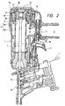
- Figs. 1, 2 and 3 are views showing a nailing machine of the present invention.
- a body 1 of the nailing machine there are provided an air chamber 2 to store compressed air supplied from a compressed air source (not shown), and a striking cylinder and piston mechanism 3.
- a trigger lever 4 When a trigger lever 4 is pulled by an operator, compressed air is supplied to and discharged from a striking cylinder 3a by the operation of a start valve 5 and a head valve 6 which are interlocked with the trigger lever 4.
- a striking piston 3b is reciprocated in the striking cylinder 3a.
- a driver 7 integrally connected with the striking piston 3b is shot to a nose portion 8 arranged at an end of the body 1, so that a nail 9 supplied to an outlet of the nose portion 8 is struck by the driver 7. In this way, the nail 9 is driven into an object to be nailed.
- the trigger lever 4 pushes a stem 10 of the start valve 5, so that a pilot valve 11 is moved downward and an air passage 12 is open to an exhaust port 13. Due to the foregoing, compressed air in an upper chamber 14 of the head valve 6 is exhausted from an exhaust port 13, so that the head valve 6 is opened, and compressed air in the air chamber 2 is suddenly supplied into the striking cylinder 3a, and the striking piston 3b is driven so as to drive a nail.
- the trigger lever 4 is returned. Then the valve stem 10 of the start valve 5 is moved downward by the action of a spring 15. At the same time, the pilot valve 11 is moved upward, and compressed air is supplied again from the air passage 12 to the upper chamber 14 of the head valve, so that the head valve 6 is closed, and at the same time, the discharge port is opened and the compressed air supplied into the striking cylinder 3a is discharged outside. At the same time, the striking piston 3b is moved upward by the compressed air, which was compressed in the process of striking, stored in the block chamber 16 arranged around the striking cylinder 3a. Therefore, the striking piston 3b returns to the initial uppermost point so as to prepare the next nail driving operation.
- a cylindrical inner cap 17 having a bottom, in which a drive valve mechanism (head valve 6) is accommodated. By the drive valve mechanism, the striking cylinder 3a is changed over between the air supply source and the atmosphere.
- a drive valve mechanism head valve 6
- the striking cylinder 3a is changed over between the air supply source and the atmosphere.
- an exhaust hole 18 for the exhaust air discharged from the striking cylinder 3a.
- the circumference of the inner cap 17 is covered with a cylinder cap 19.
- an exhaust chamber 20 that is formed along the inside of the body 1.
- the exhaust chamber 20 is a space for diffusing the exhaust air sent from the striking cylinder and piston mechanism.
- a throttle hole 21 for discharging the exhaust air sent from the exhaust chamber 20.
- the body 1 is arranged as follows.
- the lower end surface of the cylinder cap 19 is butted to the upper end surface of the main body 1a having the striking cylinder-piston mechanism, and both of them are integrally connected with each other by the fixing bolts 24.
- the wall thickness of the main body 1a is small, it is formed to be cylindrical, so that the pressure proof property can be ensured.
- both sides are formed into the same cylindrical shape, the wall thickness of which is small, as that of the outside of the inner cap 17.
- four protrusions 25, the wall thickness of which is large are formed, and a portion of the exhaust chamber 20 is formed when the outside of the protrusions 25 are connected with each other by a large arc.
- the lower portion of the main body 1a is formed to be cylindrical, and the air chamber 2 and the blow-back chamber 16 are defined between the main body 1a and the outer circumferential surface of the striking cylinder 3a.
- a recess 26 Between the protrusions 25 which are adjacent to each other, there is formed a recess 26, the wall thickness of which is small.
- an attaching hole 27 In the protrusion 25, there is formed an attaching hole 27.
- the attaching hole 27 is open to the upper end surface of the main body 1a. The reason why the protrusions 25 are formed on the main body 1a by means of padding is that the portions around the attaching holes 27 are weakest in the mechanical strength when pressure is applied.
- insertion holes into which the fixing bolts 24 are inserted, corresponding to the protrusions 25 of the main body 1a.
- the fixing bolts 24 inserted into these insertion holes are screwed into the attaching holes 27 open to the upper end surface of the main body 1a.
- a throttle hole 21 Inside the cylinder cap 19 at the lower end portion, there is formed a throttle hole 21 for discharging the exhaust air sent from the exhaust chamber 20.
- an exhaust cover 23 At the lower portion of the exhaust chamber 20 inside the cylinder cap 19, there is provided an exhaust cover 23.
- the exhaust cover 23 has a large number of exhaust holes 22 and covers the outside of the recess 26, the wall thickness of which is small, formed between the protrusions 25 which are adjacent to each other. Due to the foregoing arrangement, an exhaust passage 28 is formed between the exhaust cover 23 and the recess 26. The upper end of this exhaust passage 28 is open to the throttle hole 21.
- the exhaust air discharged from the striking cylinder 3a is diffused from the exhaust port 18 into the exhaust chamber 20 at a stroke. Further, the exhaust air in the exhaust chamber 20 is diffused and discharged from the throttle hole 21. Therefore, compared with a case in which the exhaust air is directly discharged outside from the exhaust port 18, the level of exhaust sound of the nailing machine of this embodiment is remarkably reduced.
- the exhaust chamber 20 is formed along the side of the body 1. Accordingly, the exhaust chamber 20 can be ensured without increasing the total height of the nailing machine. From this viewpoint, it is possible to avoid the increase in the size of the nailing machine.
- the wall thickness of a portion in which padding is not required is reduced. Due to the foregoing, the recess 26 is formed between the protrusions 25 adjacent to each other. This recess 26 is used as an attaching portion in which the exhaust cover 23 is attached. Therefore, the size of the overall body is not increased more than the needed size.
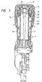
- FIGs. 8, 9 and 10 are views showing another nailing machine of the present invention.
- This nailing machine is similar to the nailing machine of the first embodiment as follows.
- an air chamber 102 to store compressed air supplied from a compressed air source (not shown), and a striking cylinder-piston mechanism 103.
- a trigger lever 104 When a trigger lever 104 is pulled by an operator, compressed air is supplied to and discharged from a striking cylinder 103a by the operation of a start valve 105 and a head valve 106 which are interlocked with the trigger lever 104.
- a striking piston 103b is reciprocated in the striking cylinder 103a.
- a driver 107 integrally connected with the striking piston 103b is shot to a nose portion 108 arranged at an end of the body 101, so that a nail 109 supplied to an outlet of the nose portion 108 is struck by the driver 107. In this way, the nail 109 is driven into an object to be nailed.
- the trigger lever 104 pushes a stem 110 of the start valve 105, so that a pilot valve 111 is moved downward and an air passage 112 is open to an exhaust port 113. Due to the foregoing, compressed air in an upper chamber 114 of the head valve 106 is exhausted from an exhaust port 113, so that the head valve 106 is opened, and compressed air in the air chamber 102 is suddenly supplied into the striking cylinder 103a, and the striking piston 103b is driven so as to drive a nail.
- the trigger lever 104 is returned. Then the valve stem 110 of the start valve 105 is moved downward by the action of a spring 115. At the same time, the pilot valve 111 is moved upward, and compressed air is supplied again from the air passage 112 to the upper chamber 114 of the head valve, so that the head valve 106 is closed, and at the same time, the discharge port is opened and the compressed air supplied into the striking cylinder 103a is discharged outside. At the same time, the striking piston 103b is moved upward by the compressed air, which was compressed in the process of striking, stored in the blow-back chamber 116 arranged around the striking cylinder 103a. Therefore, the striking piston 103b returns to the initial uppermost point so as to prepare the next nail driving operation.
- the exhaust air discharged from the striking cylinder 103a is sent from the exhaust port 118 of the inner cap 117 into the exhaust chamber 120 at a stroke. Further, the exhaust air in the exhaust chamber 120 is diffused and discharged from the throttle port 121. Therefore, the level of exhaust sound is remarkably reduced as compared with an arrangement in which the exhaust air is directly discharged outside from the exhaust port 118.
- the exhaust air discharged from the striking cylinder 103a is quickly sent into the exhaust chamber 120. Accordingly, the exhaust of air from the striking cylinder 103a is not delayed. Therefore, the returning performance of the striking piston 103b is not deteriorated even if the sound of exhaust air is reduced as described above.
- the exhaust chamber 120 is not provided in such a manner that a cover is simply attached to the outer circumference of the cylinder cap 119 while a space is provided between the cylinder cap 119 and the cover, but the exhaust chamber 120 is formed along the side of the body 101. Accordingly, even if the height of the overall nailing machine is not increased, the exhaust air chamber 120 can be positively formed. From this viewpoint, the nailing machine can be made compact.
- the size of the throttle hole 121 may be adjusted to be small as follows. As shown in Fig. 12, an attaching space 124 is formed in the upper portion of the throttle hole 121 of the exhaust chamber 120. In this attaching space 124, there is provided an arcuate baffle member 125 shown in Fig. 13. Due to this baffle member 125, the size of the throttle hole 121 can be more reduced.
- the size of the throttle hole 121 of the exhaust chamber 120 is adjustable as described above. Accordingly, in a packing work in which they attach importance to the speed of driving nails even if the level of sound is raised, the above baffle member 125 is not attached. In a conventional architectural method in which they attach importance to the effect of sound reduction rather than the speed of driving nails, the above baffle member 125 is attached so as to enhance the effect of sound reduction.
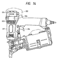
- FIGs. 14, 15 and 16 are views showing still further nailing machine of the present invention.
- This nailing machine is arranged as follows.
- an air chamber 202 to store compressed air of high pressure supplied from a compressed air source (not shown), and a cylindrical striking cylinder-piston mechanism 203.
- a trigger lever 204 When a trigger lever 204 is pulled by an operator, compressed air is supplied to and discharged from a striking cylinder 203a by the operation of a start valve 205 and a head valve 206 which are interlocked with the trigger lever 204.
- a striking piston 203b is reciprocated in the striking cylinder 203a.
- a driver 207 integrally connected with the striking piston 203b is shot to a nose portion 209 arranged at an end of the body 201, so that a nail 208 supplied to an outlet of the nose portion 209 is struck by the driver 207. In this way, the nail 208 is driven into an object to be nailed.
- the start valve 205 includes a cylindrical pilot valve 211 slidably arranged in the valve housing 210, and a valve stem 212 slidably arranged in the pilot valve 211.
- the compressed air sent from the air chamber 202 is supplied between the pilot valve 211 and the lower bottom portion of the valve housing 210, so that the pilot valve 211 can be pushed upward.
- the pilot valve 211 moved upward the air passage 214 communicated with the upper chamber 213 of the head valve 206 is opened to the air chamber 202, and the exhaust port 215 of the upper end of the valve housing 210 is closed.
- the valve stem 212 is pushed, resisting the spring force, by the operation of the trigger lever 204 as shown in Fig.
- the compressed air which has been supplied, is discharged from the stem guide hole 217 at the lower end of the valve housing 210. Due to the foregoing, the pilot valve 211 is moved downward, so that the air passage 214 is closed to the air chamber 202 and opened to the exhaust port 215 arranged at the upper end of the valve housing 210.
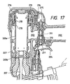
- an annular protruding edge 218 On the upper outside of the striking cylinder 203a, there is provided an annular protruding edge 218.
- a short cylindrical head valve 206 is arranged on the same axis as that of the striking cylinder 203a, and this head valve 206 can be slid upward and downward.
- the protruding edge 218 and the outer wall surface of the striking cylinder 203a are covered with a cover 219 integrally made of rubber.
- the lower end of the head valve 206 comes into contact with the protruding edge 218 and receives a force generated by the compressed air introduced from the air chamber 202.
- the head valve 206 is located at a lower position, and the lower end of the head valve 206 comes into contact with the protruding edge 218, so that the air chamber 202 is closed to the striking cylinder 203a.
- the compressed air is discharged from the upper chamber 213 as shown in Fig.
- the head valve 206 is slid upward, and the lower end of the head valve 206 is separated from the protruding edge 218, so that the air passage between the striking cylinder 203a and the head valve 206 is opened, and the air chamber 202 is connected with the striking cylinder 203a.
- an inner cap 221 having an exhaust port 220.
- a cylinder cap 222 around the inner cap 221.
- an exhaust chamber 223 between the cylinder cap 222 and the inner cap 221.
- a throttle hole 224 In the lower portion of the throttle hole 224, there is provided an exhaust cover 226 having an exhaust port 225. As described above, the exhaust air discharged from the exhaust hole 220 of the inner cap 221 is discharged outside via the exhaust chamber 223 formed along the inside of the body 201.
- the exhaust hole 220 of the inner cap 221 is opened.
- the exhaust hole 220 of the inner cap 221 is closed.
- the trigger lever 204 is pulled as shown in Fig. 17 so that the valve stem 212 of the start valve 205 is pushed. Then the pilot valve 211 is moved downward, and the air passage 214 is opened to the exhaust port 215, so that the compressed air in the upper chamber 213 is discharged from the exhaust port 215, and the head valve 206 is opened. Therefore, the compressed air in the air chamber 202 is suddenly supplied into the striking cylinder 203a via the air passage formed between the striking cylinder 203a and the head valve 206. When the compressed air in the air chamber 202 is suddenly supplied into the striking cylinder 203a, the striking piston 203b is driven.
- the trigger lever 204 is returned. Then, as shown in Fig. 15, the valve stem 212 of the start valve 205 is moved downward by the action of a spring. At the same time, the pilot valve 211 is moved upward, and compressed air is supplied again from the air passage 214 to the upper chamber 213 of the head valve, so that the head valve 206 is closed, and at the same time, the discharge port 220 of the inner cap 221 is opened and the compressed air supplied into the striking cylinder 203a is discharged outside from the exhaust chamber 223 via the exhaust port 215.
- the striking piston 203b is moved upward by the compressed air, which was compressed by the striking piston 203b in the process of striking, stored in the block chamber 227 arranged around the striking cylinder 203a. Therefore, the striking piston 203b moves upward and returns to the initial uppermost point so as to prepare the next nail driving operation.
- the air passage is formed between the striking cylinder 203a and the head valve 206 as shown in Fig. 17.
- the head valve 206 is opened and the compressed air of high pressure is supplied into the striking cylinder 203a, the inner pressure of which has been reduced in the previous exhaust operation, the compressed air is suddenly expanded. Due to this adiabatic expansion, temperatures of the protruding edge 218 of the striking cylinder 203a and the upper outer wall surface are lowered. However, these portions are covered with the cover 219 made of rubber. Accordingly, even if the moisture contained in the compressed air is frozen and ice is generated, it is difficult for the generated ice to adhere to the cover 219 made of elastic rubber, the heat insulating property of which is high.
- the head valve 206 can be sealed in a good condition and no air leaks out. Accordingly, the head valve 206 can be always operated properly.
- the head valve 206 is made of synthetic resin, the heat insulating property of which is high, the freeze of moisture contained in the compressed air can be further prevented.
- the head valve of the present invention is not limited to the above example.
- the head valve may be arranged as shown in Fig. 18.
Landscapes
- Physics & Mathematics (AREA)
- Fluid Mechanics (AREA)
- Engineering & Computer Science (AREA)
- Mechanical Engineering (AREA)
- Portable Nailing Machines And Staplers (AREA)
Claims (4)
- Mécanisme d'échappement d'une machine à clouer pneumatique dans laquelle un cylindre de frappe (3a, 103a, 203a) est reçu dans un corps (1, 101, 201) et un piston de frappe (3b, 103b, 203b) situé dans le cylindre de frappe est entraíné pour entraíner un clou (9, 109, 208) lorsque de l'air comprimé est alimenté vers une partie supérieure du cylindre de frappe et s'échappe à partir de celle-ci, caractérisé en ce que le mécanisme d'échappement comporte :un capuchon intérieur (17, 117, 221) agencé dans la partie supérieure du cylindre de frappe,un capuchon de cylindre (19, 119, 222) recouvrant le capuchon intérieur,une chambre d'échappement (20, 120, 223) formée le long de la partie intérieure du corps (1, 101, 201) entre le capuchon intérieur (17, 117, 221) et le capuchon de cylindre (19, 119, 222), etun trou d'étranglement (21, 121, 224) formé dans une partie inférieure de la chambre d'échappement (20, 120, 223), dans lequel l'air d'échappement échappé à partir de la partie supérieure du cylindre de frappe (3a, 103a, 203a) est évacué à partir du trou d'étranglement (21, 121, 224) via la chambre d'échappement.
- Mécanisme d'échappement selon la revendication 1, dans lequel la dimension du trou d'étranglement (21, 121, 224) est ajustable.
- Mécanisme d'échappement selon la revendication 1 ou 2, comportant de plus :un couvercle (219) constitué de caoutchouc relié à l'extérieur de la partie supérieure du cylindre de frappe (3a, 103a, 203a).
- Mécanisme d'échappement d'une machine à clouer pneumatique selon l'une quelconque des revendications précédentes, dans laquelle
un mécanisme à cylindre-piston de frappe (3, 103, 203) ayant le cylindre de frappe (3a, 103a, 203a) et le piston de frappe (3b, 103b, 203b) reçus dans celui-ci, est reçu dans un corps principal cylindrique (1a),
le capuchon de cylindre (19, 119, 222) est cylindrique et a un fond destiné à recouvrir une partie supérieure du mécanisme à cylindre-piston de frappe (3, 103, 203), la surface d'extrémité inférieure du capuchon de cylindre (19, 119, 222) étant en butée sur une surface d'extrémité supérieure du corps principal (1a),
le mécanisme d'échappement comporte de plus un boulon de fixation (24) implanté dans le capuchon de cylindre, vissé dans un trou de fixation (27) ouvrant sur la surface d'extrémité supérieure du corps principal (la),
le capuchon intérieur (17, 117, 221) est agencé à l'intérieur du capuchon de cylindre (19, 119, 222) et reçoit un mécanisme formant vanne d'entraínement (6, 106, 206) pour commuter la connexion du cylindre de frappe entre une source d'alimentation en air et l'atmosphère,
la chambre d'échappement (20, 120, 223) formée entre le capuchon intérieur (17, 117, 221) et le capuchon de cylindre (19, 119, 222) diffuse l'air d'échappement envoyé à partir du mécanisme à cylindre-piston de frappe (3, 103, 203),
le trou d'étranglement (21, 121, 224) destiné à évacuer l'air d'échappement envoyé à partir de la chambre d'échappement est formé à l'intérieur d'une extrémité inférieure du capuchon de cylindre,
le mécanisme d'échappement comporte une pluralité de saillies (25), dont l'épaisseur de paroi est plus grande que les autres parties, agencées sur la surface circonférentielle du corps principal (1a), le trou de fixation (27) étant formé dans chaque saillie (25) à des intervalles prédéterminés, et
le mécanisme d'échappement comporte de plus un couvercle d'échappement (23, 123, 226) ayant un grand nombre d'orifices d'échappement (22, 122, 225), le couvercle d'échappement (23, 123, 226) recouvrant la partie extérieure d'au moins un évidement mince (26) formé entre les saillies (25) adjacentes l'une à l'autre, dans lequel un passage d'échappement (28) est formé entre le couvercle d'échappement (23, 123) et l'évidement (26), et une extrémité supérieure du passage d'échappement (28) est ouverte vers le trou d'étranglement (21, 121, 224).
Applications Claiming Priority (9)
| Application Number | Priority Date | Filing Date | Title |
|---|---|---|---|
| JP16820495A JP3335502B2 (ja) | 1995-06-09 | 1995-06-09 | 空気圧式釘打機のヘッドバルブの凍り付き防止機構 |
| JP168203/95 | 1995-06-09 | ||
| JP168204/95 | 1995-06-09 | ||
| JP16820395 | 1995-06-09 | ||
| JP07168211A JP3099285B2 (ja) | 1995-06-09 | 1995-06-09 | 空気圧式釘打機における排気機構 |
| JP16821195 | 1995-06-09 | ||
| JP16820395A JP3211225B2 (ja) | 1995-06-09 | 1995-06-09 | 空気圧式釘打機の減音機構 |
| JP16820495 | 1995-06-09 | ||
| JP168211/95 | 1995-06-09 |
Publications (3)
| Publication Number | Publication Date |
|---|---|
| EP0747175A2 EP0747175A2 (fr) | 1996-12-11 |
| EP0747175A3 EP0747175A3 (fr) | 1997-10-01 |
| EP0747175B1 true EP0747175B1 (fr) | 2003-08-27 |
Family
ID=27322973
Family Applications (1)
| Application Number | Title | Priority Date | Filing Date |
|---|---|---|---|
| EP96109193A Expired - Lifetime EP0747175B1 (fr) | 1995-06-09 | 1996-06-07 | Système d'évacuation d'air pour une machine à clouer |
Country Status (3)
| Country | Link |
|---|---|
| US (1) | US5878936A (fr) |
| EP (1) | EP0747175B1 (fr) |
| DE (1) | DE69629623T2 (fr) |
Cited By (2)
| Publication number | Priority date | Publication date | Assignee | Title |
|---|---|---|---|---|
| US9004338B2 (en) | 2008-12-24 | 2015-04-14 | Globalforce Ip Limited | Adjustable dose chamber |
| DE102022118331A1 (de) | 2022-07-21 | 2024-02-01 | Raimund Beck Nageltechnik Gmbh | Nagelschussgerät, Verfahren zum Umbauen sowie Verfahren zur Nutzung eines solchen |
Families Citing this family (32)
| Publication number | Priority date | Publication date | Assignee | Title |
|---|---|---|---|---|
| US5860580A (en) * | 1996-05-03 | 1999-01-19 | Illinois Tool Works Inc. | Piston retention device for combustion-powered tools |
| JP3622193B2 (ja) * | 1999-03-04 | 2005-02-23 | マックス株式会社 | 釘打機、タッカ等のバンパ |
| US6572000B2 (en) * | 1999-12-03 | 2003-06-03 | Hitachi Koki Co., Ltd. | Driving tool |
| USD438079S1 (en) | 2000-02-09 | 2001-02-27 | Max Co., Ltd. | Pneumatic nailing machine |
| US6609646B2 (en) * | 2001-02-08 | 2003-08-26 | Black & Decker Inc. | Magazine assembly for fastening tool |
| EP1366863B1 (fr) * | 2002-05-31 | 2008-05-14 | Hitachi Koki Co., Ltd. | Pistolet à clouer avec dispositif de dépoussiérage |
| AU156537S (en) * | 2003-09-24 | 2004-09-29 | Max Co Ltd | Pneumatic nailing machine |
| USD498127S1 (en) | 2003-11-19 | 2004-11-09 | Porter-Cable Corporation | Pneumatic fastener |
| USD551931S1 (en) * | 2003-11-19 | 2007-10-02 | Black & Decker Inc. | Pneumatic fastener |
| JP4996044B2 (ja) * | 2004-07-09 | 2012-08-08 | 日立工機株式会社 | 打込機 |
| JP4650610B2 (ja) * | 2004-08-19 | 2011-03-16 | マックス株式会社 | 圧縮空気釘打機のメインバルブ機構 |
| USD518698S1 (en) * | 2005-01-11 | 2006-04-11 | Eastway Fair Company Ltd. | Coil roofing nailer |
| USD549538S1 (en) * | 2005-05-21 | 2007-08-28 | Jeil Tacker Co., Ltd. | Portable air nailer |
| JP4923461B2 (ja) * | 2005-07-20 | 2012-04-25 | マックス株式会社 | 打込み工具の低全高構造 |
| USD528889S1 (en) * | 2005-09-05 | 2006-09-26 | Max Co., Ltd. | Pneumatic nailing machine |
| JP4687572B2 (ja) * | 2006-06-14 | 2011-05-25 | 日立工機株式会社 | 打込機 |
| TW200821103A (en) * | 2006-11-03 | 2008-05-16 | Basso Ind Corp | Dust-removing structure of nail gun |
| US20080290132A1 (en) * | 2007-05-24 | 2008-11-27 | Chia-Sheng Liang | Main Air Valve for Pneumatic Nail Gun |
| US8028881B2 (en) * | 2009-02-20 | 2011-10-04 | Robert Bosch Gmbh | Nailer strike plate |
| JP5310311B2 (ja) * | 2009-06-29 | 2013-10-09 | マックス株式会社 | 衝撃工具用バンパ及び衝撃工具 |
| US9339925B2 (en) | 2010-07-01 | 2016-05-17 | Stanley Fastening Systems, L.P. | Fastener driving device with dust blower |
| TWI387514B (zh) | 2010-09-20 | 2013-03-01 | 鑽全實業股份有限公司 | High pressure nail gun that eliminates exhaust noise |
| EP2747945B1 (fr) * | 2011-08-23 | 2015-08-12 | Hitachi Koki Co., Ltd. | Outil de fixation |
| US9662777B2 (en) | 2013-08-22 | 2017-05-30 | Techtronic Power Tools Technology Limited | Pneumatic fastener driver |
| CN103707266B (zh) * | 2014-01-10 | 2015-07-22 | 浙江荣鹏气动工具有限公司 | 气动钉枪 |
| CA2943806C (fr) | 2014-03-27 | 2022-05-31 | Techtronic Power Tools Technology Limited | Dispositif d'entrainement d'attache motorise et son procede de fonctionnement |
| JP6578816B2 (ja) * | 2015-08-24 | 2019-09-25 | マックス株式会社 | 打込み工具 |
| JP6540372B2 (ja) * | 2015-08-24 | 2019-07-10 | マックス株式会社 | 打込み工具 |
| US10639776B2 (en) * | 2016-12-22 | 2020-05-05 | Makita Corporation | Driving tool |
| JP7114934B2 (ja) * | 2018-03-01 | 2022-08-09 | マックス株式会社 | 空気圧工具 |
| DE102018121999B4 (de) * | 2018-09-10 | 2023-08-31 | Autoliv Development Ab | Pyrotechnische Straffvorrichtung für einen Sicherheitsgurt einer Sicherheitsgurteinrichtung mit einer Kraftbegrenzungseinrichtung |
| JP7298710B2 (ja) * | 2019-11-28 | 2023-06-27 | 工機ホールディングス株式会社 | 打込機 |
Family Cites Families (13)
| Publication number | Priority date | Publication date | Assignee | Title |
|---|---|---|---|---|
| US3673922A (en) * | 1966-12-19 | 1972-07-04 | Fastener Corp | Fastener driving tool |
| US4039113A (en) * | 1976-04-16 | 1977-08-02 | Textron, Inc. | Pneumatically operated fastener driving device with improved main valve assembly |
| US4566619A (en) * | 1980-07-24 | 1986-01-28 | The Kiesel Co. | Pneumatic fastener-driving tool and method |
| US4401251A (en) * | 1980-11-19 | 1983-08-30 | Signode Corporation | Bumperless gun nailer |
| DE3119956C2 (de) * | 1981-05-20 | 1984-11-22 | Joh. Friedrich Behrens AG, 2070 Ahrensburg | Schallgedämpftes Eintreibgerät für Befestigungsmittel |
| US4503585A (en) * | 1983-04-14 | 1985-03-12 | Hantover, Inc. | Pneumatic stunner |
| US5259465A (en) * | 1990-01-10 | 1993-11-09 | Makita Electric Works, Ltd. | Filter for a pneumatic tool |
| US5110030A (en) * | 1990-08-10 | 1992-05-05 | Hitachi Koki Co., Ltd. | Pneumatic fastener driving tool having an air exhaust arrangement |
| US5181450A (en) * | 1991-05-16 | 1993-01-26 | Umberto Monacelli | Pneumatic fastener driving apparatus with piston holding detent |
| US5197646A (en) * | 1992-03-09 | 1993-03-30 | Illinois Tool Works Inc. | Combustion-powered tool assembly |
| GB2265106B (en) * | 1992-03-18 | 1995-07-05 | Max Co Ltd | Air-pressure-operated impulsion mechanism |
| EP0584395A1 (fr) * | 1992-08-28 | 1994-03-02 | Umberto Monacelli | Appareil de scellement pneumatique avec piston perfectionné |
| US5476205A (en) * | 1994-12-22 | 1995-12-19 | Stanley-Bostitch, Inc. | Make and break head valve assembly |
-
1996
- 1996-06-07 EP EP96109193A patent/EP0747175B1/fr not_active Expired - Lifetime
- 1996-06-07 US US08/657,882 patent/US5878936A/en not_active Expired - Fee Related
- 1996-06-07 DE DE69629623T patent/DE69629623T2/de not_active Expired - Fee Related
Cited By (2)
| Publication number | Priority date | Publication date | Assignee | Title |
|---|---|---|---|---|
| US9004338B2 (en) | 2008-12-24 | 2015-04-14 | Globalforce Ip Limited | Adjustable dose chamber |
| DE102022118331A1 (de) | 2022-07-21 | 2024-02-01 | Raimund Beck Nageltechnik Gmbh | Nagelschussgerät, Verfahren zum Umbauen sowie Verfahren zur Nutzung eines solchen |
Also Published As
| Publication number | Publication date |
|---|---|
| US5878936A (en) | 1999-03-09 |
| DE69629623D1 (de) | 2003-10-02 |
| EP0747175A3 (fr) | 1997-10-01 |
| DE69629623T2 (de) | 2004-06-17 |
| EP0747175A2 (fr) | 1996-12-11 |
Similar Documents
| Publication | Publication Date | Title |
|---|---|---|
| EP0747175B1 (fr) | Système d'évacuation d'air pour une machine à clouer | |
| US5927584A (en) | Pneumatic fastener driving tool having air exhaust arrangement | |
| US6578750B2 (en) | Nail hammering guide mechanism in nailing machine | |
| US5476205A (en) | Make and break head valve assembly | |
| JPH02198775A (ja) | 空冷バンパ付き駆動工具 | |
| US2960067A (en) | Single stroke air hammer | |
| US6745928B2 (en) | Trigger valve apparatus for pneumatic tool | |
| US7296721B1 (en) | Pneumatic nail gun having nail pusher | |
| JPH10113883A (ja) | 完全サイクル弁をもつファスナー駆動装置 | |
| AU2005201108B2 (en) | Fastener driving tool and magazine device | |
| JP4650610B2 (ja) | 圧縮空気釘打機のメインバルブ機構 | |
| US8002160B2 (en) | Combustion fastener | |
| JP3099285B2 (ja) | 空気圧式釘打機における排気機構 | |
| US7395954B2 (en) | Pneumatic nail gun | |
| JP3211225B2 (ja) | 空気圧式釘打機の減音機構 | |
| JP3289763B2 (ja) | 空気圧式釘打機の排気カバー | |
| JP3137229B2 (ja) | 釘打機における起動用エアの排出機構 | |
| JP4026313B2 (ja) | 空気釘打機 | |
| US7204402B2 (en) | Pneumatic tool with as-cast air signal passage | |
| JP2004001135A (ja) | エアダスタ付き釘打機 | |
| JP2002137173A (ja) | 空気釘打機 | |
| JP3335502B2 (ja) | 空気圧式釘打機のヘッドバルブの凍り付き防止機構 | |
| JPH0516158U (ja) | 釘打機のヘツドバルブ | |
| JPS6236621Y2 (fr) | ||
| JP4174726B2 (ja) | 空気釘打機 |
Legal Events
| Date | Code | Title | Description |
|---|---|---|---|
| PUAI | Public reference made under article 153(3) epc to a published international application that has entered the european phase |
Free format text: ORIGINAL CODE: 0009012 |
|
| AK | Designated contracting states |
Kind code of ref document: A2 Designated state(s): DE FR GB |
|
| PUAL | Search report despatched |
Free format text: ORIGINAL CODE: 0009013 |
|
| AK | Designated contracting states |
Kind code of ref document: A3 Designated state(s): DE FR GB |
|
| 17P | Request for examination filed |
Effective date: 19980401 |
|
| 17Q | First examination report despatched |
Effective date: 20010323 |
|
| GRAH | Despatch of communication of intention to grant a patent |
Free format text: ORIGINAL CODE: EPIDOS IGRA |
|
| GRAH | Despatch of communication of intention to grant a patent |
Free format text: ORIGINAL CODE: EPIDOS IGRA |
|
| GRAA | (expected) grant |
Free format text: ORIGINAL CODE: 0009210 |
|
| AK | Designated contracting states |
Designated state(s): DE FR GB |
|
| REG | Reference to a national code |
Ref country code: GB Ref legal event code: FG4D |
|
| REF | Corresponds to: |
Ref document number: 69629623 Country of ref document: DE Date of ref document: 20031002 Kind code of ref document: P |
|
| ET | Fr: translation filed | ||
| PLBE | No opposition filed within time limit |
Free format text: ORIGINAL CODE: 0009261 |
|
| STAA | Information on the status of an ep patent application or granted ep patent |
Free format text: STATUS: NO OPPOSITION FILED WITHIN TIME LIMIT |
|
| 26N | No opposition filed |
Effective date: 20040528 |
|
| PGFP | Annual fee paid to national office [announced via postgrant information from national office to epo] |
Ref country code: GB Payment date: 20090603 Year of fee payment: 14 Ref country code: DE Payment date: 20090604 Year of fee payment: 14 |
|
| GBPC | Gb: european patent ceased through non-payment of renewal fee |
Effective date: 20100607 |
|
| REG | Reference to a national code |
Ref country code: FR Ref legal event code: ST Effective date: 20110228 |
|
| PG25 | Lapsed in a contracting state [announced via postgrant information from national office to epo] |
Ref country code: DE Free format text: LAPSE BECAUSE OF NON-PAYMENT OF DUE FEES Effective date: 20110101 |
|
| PG25 | Lapsed in a contracting state [announced via postgrant information from national office to epo] |
Ref country code: FR Free format text: LAPSE BECAUSE OF NON-PAYMENT OF DUE FEES Effective date: 20100630 |
|
| PG25 | Lapsed in a contracting state [announced via postgrant information from national office to epo] |
Ref country code: GB Free format text: LAPSE BECAUSE OF NON-PAYMENT OF DUE FEES Effective date: 20100607 |
|
| PGFP | Annual fee paid to national office [announced via postgrant information from national office to epo] |
Ref country code: FR Payment date: 20090611 Year of fee payment: 14 |