EP0748670A1 - An actuation apparatus - Google Patents
An actuation apparatus Download PDFInfo
- Publication number
- EP0748670A1 EP0748670A1 EP96303854A EP96303854A EP0748670A1 EP 0748670 A1 EP0748670 A1 EP 0748670A1 EP 96303854 A EP96303854 A EP 96303854A EP 96303854 A EP96303854 A EP 96303854A EP 0748670 A1 EP0748670 A1 EP 0748670A1
- Authority
- EP
- European Patent Office
- Prior art keywords
- movable member
- actuating means
- workpiece
- coils
- forces
- Prior art date
- Legal status (The legal status is an assumption and is not a legal conclusion. Google has not performed a legal analysis and makes no representation as to the accuracy of the status listed.)
- Granted
Links
Images


Classifications
-
- H—ELECTRICITY
- H02—GENERATION; CONVERSION OR DISTRIBUTION OF ELECTRIC POWER
- H02K—DYNAMO-ELECTRIC MACHINES
- H02K41/00—Propulsion systems in which a rigid body is moved along a path due to dynamo-electric interaction between the body and a magnetic field travelling along the path
- H02K41/02—Linear motors; Sectional motors
-
- B—PERFORMING OPERATIONS; TRANSPORTING
- B23—MACHINE TOOLS; METAL-WORKING NOT OTHERWISE PROVIDED FOR
- B23Q—DETAILS, COMPONENTS, OR ACCESSORIES FOR MACHINE TOOLS, e.g. ARRANGEMENTS FOR COPYING OR CONTROLLING; MACHINE TOOLS IN GENERAL CHARACTERISED BY THE CONSTRUCTION OF PARTICULAR DETAILS OR COMPONENTS; COMBINATIONS OR ASSOCIATIONS OF METAL-WORKING MACHINES, NOT DIRECTED TO A PARTICULAR RESULT
- B23Q17/00—Arrangements for observing, indicating or measuring on machine tools
- B23Q17/22—Arrangements for observing, indicating or measuring on machine tools for indicating or measuring existing or desired position of tool or work
-
- B—PERFORMING OPERATIONS; TRANSPORTING
- B23—MACHINE TOOLS; METAL-WORKING NOT OTHERWISE PROVIDED FOR
- B23Q—DETAILS, COMPONENTS, OR ACCESSORIES FOR MACHINE TOOLS, e.g. ARRANGEMENTS FOR COPYING OR CONTROLLING; MACHINE TOOLS IN GENERAL CHARACTERISED BY THE CONSTRUCTION OF PARTICULAR DETAILS OR COMPONENTS; COMBINATIONS OR ASSOCIATIONS OF METAL-WORKING MACHINES, NOT DIRECTED TO A PARTICULAR RESULT
- B23Q5/00—Driving or feeding mechanisms; Control arrangements therefor
- B23Q5/22—Feeding members carrying tools or work
- B23Q5/28—Electric drives
-
- H—ELECTRICITY
- H01—ELECTRIC ELEMENTS
- H01F—MAGNETS; INDUCTANCES; TRANSFORMERS; SELECTION OF MATERIALS FOR THEIR MAGNETIC PROPERTIES
- H01F7/00—Magnets
- H01F7/06—Electromagnets; Actuators including electromagnets
- H01F7/066—Electromagnets with movable winding
Definitions
- the present invention relates to an actuation apparatus for positioning a workpiece, and in particular to an electromagnetic actuation apparatus.
- a well known actuation apparatus uses a solenoid and an iron armature connectable to the workpiece to be moved.
- DC Current flow in electrically conductive windings in the solenoid produces a magnetic field which moves the iron armature to a fixed "on” position. As the armature moves, so does the workpiece. When the current flow stops the iron armature is returned to its home or “off” position by a spring. With this actuation device, it is only possible to move the workpiece between two positions depending upon whether the solenoid is "on” or "off”.
- an actuation apparatus for positioning a workpiece, including a movable member connectable to said workpiece, and electromagnetic actuating means energizable to produce a force on said movable member in a predetermined direction, characterized in that said movable member is of electrically conducting material, and in that said actuating means is connected to an AC voltage supply, said force being caused by the interaction of eddy currents induced in said movable member with the magnetic field produced by said actuating means.
- an actuation apparatus for positioning a workpiece, including a movable member connectable to said workpiece, and first electromagnetic actuating means energizable to produce a first force on said movable member in a first direction, characterized by second electromagnetic actuating means energizable to provide a second force acting on said movable member in a second direction opposite to said first direction, the forces produced on said movable member by energization of said first and second actuating means being dependent on the position of said movable member relative to said first and second actuating means, whereby said movable member may be moved to a desired position by appropriate energization of said first and second actuating means such that said first and second forces are equal at said desired position.
- the actuation apparatus may comprise two induction coils energizable by AC voltage supplies and electromagnetically coupled to an electrically conductive movable member, the magnetic fields producing eddy currents in the movable member.
- the response time is much quicker than for the known actuation device described above.
- the actuation device of the present invention is also robust, and requires less mechanical maintenance than known devices.
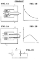
- Fig. 1A With reference to Fig. 1A there is illustrated a portion of a known solenoid actuator, the spring having been removed for clarity.
- the actuator contains an iron former 2 and a coil 4 of electrically conductive windings wound around a portion 6 of the iron former 2, adjacent an iron armature 8.
- a DC current passes through the coil 4
- a magnetic field is produced which in turn produces a force which urges the iron armature 8 towards the coil 4, as illustrated by the displacement/force diagram, Fig. 1B.
- the coil 4 has an electrical resistance R and a large inductance L, and thus a large time constant (t LR ). Consequently, the solenoid is slow to react to the current in the coil 4 being switched on and off, so that the time between switching the current on and off and the resultant movement of the iron armature 8 is long.
- Fig. 2A is a schematic view of an actuation apparatus in accordance with the present invention.
- This actuation apparatus includes an iron former 10, which is similar to that used in the known solenoid actuator except that the portion 12 of the former 10 around which the coil 14 is wound has been extended.
- the iron armature 8 of the known solenoid actuator has been replaced by a movable member 16 in the form of a hollow electrically conductive tube of copper.
- an AC current from an AC voltage supply 17 Fig. 2C
- the magnetic field in turn produces electrical eddy currents in the electrically conductive movable member 16.
- Fig. 2C illustrates an equivalent electrical circuit corresponding to the actuation apparatus, in which resistance R and inductance L correspond to the resistance and inductance of the coil 14, and resistance r corresponds to the resistance of the movable member 16.
- resistance r is in parallel with part of the inductance L, the effect of the resistance r, when a current is passed through the circuit, is to reduce the magnitude of the inductance which in turn reduces the magnitude of the time constant.
- the actuation apparatus in accordance with the present invention has a small time constant it will therefore react quickly to changes in the current supplied to the coil 14.
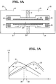
- Fig. 3A is a schematic view of an actuation apparatus in accordance with the present invention including two cooperating actuating means 20 and 30 arranged so as to urge a common movable member 22 in opposite directions when a current is supplied to each of two coils 24 and 34, as illustrated in Fig. 3B.
- the actuating means 20 and 30 respectively include two iron formers 21 and 31, adjacent ends of which are separated by a non-magnetic ring 33 as shown in Fig. 3A, and the interior portions of which are connected by a common central portion 35 on which is slidably mounted a cylindical movable member 22.
- the full lines 26 and 36 in Fig. 3B illustrate the forces F and F' applied to the common movable member 22, when AC currents of equal magnitude are supplied to the coils 24 and 34.
- the forces F and F' can be seen to be equal at a point 32, and the centre of the movable member 22 is held at rest in this position by the forces F and F' produced by the actuating means 20 and 30.
- the dashed lines 28 and 38 illustrate the forces F and F' applied to the common movable member 22 when unequal lower currents are supplied to the coils 24 and 34.
- the magnitude of each force F and F' is proportional to the square of the magnitude of the current applied to the respective coil 24,34.
- the position 39 at which these forces F and F' are equal is different, as the current supplied to the coil 24 in the actuating means 20 is less than the current supplied to the coil 34 in the actuating means 30.
- the position to which the movable member 22 is moved may be selected from a continuous range of positions between the actuating means 20 and 30. It should be understood that, in operation, a current must be maintained in each of the coils 24 and 34 in order to maintain the forces F and F' on the movable member 22 and hold the movable member 22 in the position in which the forces F and F' are equal.
- Fig. 4 and Figs. 5A, 5B and 5C illustrate an embodiment of an actuation apparatus 40 in accordance with the present invention including a main outer cylindrical body 42 which, in turn, comprises two actuating means 20' and 30' in the form of two cylindrical iron structures 43 and 44 arranged laterally adjacent one another, and separated by a circular non-magnetic spacer 51 of brass, the spacer 51 having a substantially centrally located circular aperture 52.
- Each structure 43, 44 comprises an outer iron cylindrical tube 45, 46 enclosing an inner iron cylinder 47, 48.
- Each cylinder 47, 48 has a bore 49, 50 of a frusto-conical profile for most of its length, terminating at one end with a small length of substantially constant diameter.
- the constituent parts 45, 46, 47, 48, 54, 55 of the iron structures 43 and 44 are held together, and the hollow support rod 56 is held in place, by washers 59 and 60 and nuts 61 and 62 screwed in place around threaded end portions of the hollow rod 56, the washers 59 and 60 bearing against the outer surfaces of the end plates 54 and 55.
- a copper tube 63 is concentrically mounted around, and supported by, the hollow support rod 56 within the internal cavity 53.
- the copper tube 63 is arranged to be laterally slidably movable along the supporting rod 56 as indicated by the arrows in Fig. 4.
- Secured to each end of the copper tube 63 is a set of four substantially equidistantly spaced, radially extending, metal spokes 64a-d; 65a-d.
- the spokes 64a-d; 65a-d respectively extend radially through slits 66a-d; 67a-d provided in the outer tubes 45 and 46 and inner cylinders 47 and 48 so as to protrude externally of the cylindrical body 42.
- Two coils 68 and 69 of the type well known in electromagnetic applications are provided inside the cylindrical body 42.
- the coils 68 and 69 are wound on formers 70 and 71 which are mounted on the supporting rod 56, and which are respectively located in juxtaposition with the inner faces of the end plates 54 and 55.
- the copper tube 63 is therefore movable in a direction parallel to the axes of the two coils 68 and 69.
- Each coil 68 and 69 is coupled to a separate variable single phase AC voltage supply 72, 73, as illustrated schematically in Fig. 6. For clarity, these connections are not shown in Fig. 4, but are of the kind well known to persons skilled in the art.
- the outer cylindrical body 42 has a length of 20 cm, and an outer diameter of 6 cm.
- the copper tube 63 is typically approximately 7 cm in length with an external diameter of approximately 2.5 cm.
- the cylindrical structures 43 and 44 respectively provide flux paths, for the associated coils 68 and 69, with the brass spacer 51 acting to separate the two structures 43 and 44 magnetically.
- the voltages V 1 and V 2 applied to the respective coils 68 and 69 are controlled by varying the firing delay angle of respective triacs (not shown) provided in the respective control circuits 74 and 75 coupled to the coils 68,69.
- Fig. 7 illustrates how the actuation apparatus 40 is used to selectively position a workpiece 78.
- the workpiece 78 is mounted on a mounting plate 76 of an outer cylindrical chassis 77, coupled to the radial spokes 64a-d; 65a-d of the actuation apparatus 40.
- the copper tube 63 is displaced by varying the voltages V 1 and V 2 to the respective coils 68 and 69 as described above, the radial spokes 64a-d; 65a-d are also laterally displaced, and consequently the outer chassis 77 is also displaced, thus moving the mounted workpiece 78 a corresponding distance.
- the radial spokes 64a-d; 65a-d can be attached to other shaped housings and workpiece mounts depending on the proposed application of the actuation device.
- the voltages V 1 and V 2 can be controlled in other ways, again depending on the proposed application. For example, they may be controlled by signal processing hardware and software.
Landscapes
- Engineering & Computer Science (AREA)
- Physics & Mathematics (AREA)
- Electromagnetism (AREA)
- Power Engineering (AREA)
- Mechanical Engineering (AREA)
- Chemical & Material Sciences (AREA)
- Combustion & Propulsion (AREA)
- Electromagnets (AREA)
- Portable Nailing Machines And Staplers (AREA)
- Control Of Position Or Direction (AREA)
Abstract
Description
- The present invention relates to an actuation apparatus for positioning a workpiece, and in particular to an electromagnetic actuation apparatus.
- A well known actuation apparatus uses a solenoid and an iron armature connectable to the workpiece to be moved. DC Current flow in electrically conductive windings in the solenoid produces a magnetic field which moves the iron armature to a fixed "on" position. As the armature moves, so does the workpiece. When the current flow stops the iron armature is returned to its home or "off" position by a spring. With this actuation device, it is only possible to move the workpiece between two positions depending upon whether the solenoid is "on" or "off".
- In addition, as the windings have a large electrical inductance the speed of response of the device is severely limited, as the time constant for the device is proportional to the self inductance of the windings.
- It is an object of the present invention to provide an actuation device having enhanced flexibility and a fast response time.
- According to one aspect of the present invention there is provided an actuation apparatus for positioning a workpiece, including a movable member connectable to said workpiece, and electromagnetic actuating means energizable to produce a force on said movable member in a predetermined direction, characterized in that said movable member is of electrically conducting material, and in that said actuating means is connected to an AC voltage supply, said force being caused by the interaction of eddy currents induced in said movable member with the magnetic field produced by said actuating means.
- According to another aspect of the present invention there is provided an actuation apparatus for positioning a workpiece, including a movable member connectable to said workpiece, and first electromagnetic actuating means energizable to produce a first force on said movable member in a first direction, characterized by second electromagnetic actuating means energizable to provide a second force acting on said movable member in a second direction opposite to said first direction, the forces produced on said movable member by energization of said first and second actuating means being dependent on the position of said movable member relative to said first and second actuating means, whereby said movable member may be moved to a desired position by appropriate energization of said first and second actuating means such that said first and second forces are equal at said desired position.
- The actuation apparatus may comprise two induction coils energizable by AC voltage supplies and electromagnetically coupled to an electrically conductive movable member, the magnetic fields producing eddy currents in the movable member.
- Because the currents induced in the movable member reduce the effective self inductance of the coils to virtually zero, as will be described below, the response time is much quicker than for the known actuation device described above.
- The actuation device of the present invention is also robust, and requires less mechanical maintenance than known devices.
- Embodiments of the invention will now be described, by way of example, with reference to the accompanying drawings, in which:
- Fig. 1A is a schematic view of a portion of a known solenoid actuator;
- Fig. 1B is a graphic representation of the electromagnetic force acting on a magnetic armature within the solenoid actuator of Fig. 1A;
- Fig. 2A is a schematic view of an actuation apparatus in accordance with the present invention, having a single actuating means;
- Fig. 2B is a graphic representation of the electromagnetic force acting on an electrically conductive movable member within the actuating means of Fig. 2A;
- Fig. 2C is a schematic representation of the equivalent electrical circuit corresponding to the actuating means and electrically conductive movable member of Fig. 2A;
- Fig. 3A is a schematic view of an actuation apparatus in accordance with the present invention having two cooperating actuating means;
- Fig. 3B is a graphic representation of the forces produced by the two actuating means of the apparatus of Fig. 3A;
- Fig. 4 is a longitudinal vertical cross-section of the main body of an actuation apparatus in accordance with the present invention;
- Fig. 5A is a vertical cross-section along the line II-II of Fig. 4;
- Fig. 5B is a vertical cross-section along the line III-III of Fig. 4;
- Fig. 5C is a vertical cross-section along the line IV-IV of Fig. 4;
- Fig. 6 is a schematic illustration of the operation of the actuation apparatus of Fig. 4; and
- Fig. 7 illustrates the mounting of a workpiece on the actuation apparatus of Fig. 4.
- With reference to Fig. 1A there is illustrated a portion of a known solenoid actuator, the spring having been removed for clarity. The actuator contains an iron former 2 and a
coil 4 of electrically conductive windings wound around aportion 6 of the iron former 2, adjacent aniron armature 8. As discussed above, when a DC current passes through thecoil 4, a magnetic field is produced which in turn produces a force which urges theiron armature 8 towards thecoil 4, as illustrated by the displacement/force diagram, Fig. 1B. - The
coil 4 has an electrical resistance R and a large inductance L, and thus a large time constant (tLR). Consequently, the solenoid is slow to react to the current in thecoil 4 being switched on and off, so that the time between switching the current on and off and the resultant movement of theiron armature 8 is long. - Fig. 2A is a schematic view of an actuation apparatus in accordance with the present invention. This actuation apparatus includes an iron former 10, which is similar to that used in the known solenoid actuator except that the
portion 12 of the former 10 around which thecoil 14 is wound has been extended. Also, theiron armature 8 of the known solenoid actuator has been replaced by amovable member 16 in the form of a hollow electrically conductive tube of copper. When an AC current from an AC voltage supply 17 (Fig. 2C) is passed through the coil 14 a magnetic field is produced. However, in this case the magnetic field in turn produces electrical eddy currents in the electrically conductivemovable member 16. The action of the magnetic field on the eddy currents creates a force which urges themovable member 16 away from thecoil 14, until themovable member 16 is outside the influence of the magnetic field, as illustrated in the displacement/force diagram, Fig. 2B. When thevoltage supply 17 is switched off, themovable member 16 is returned to its non-actuated position by a spring (not shown). - Fig. 2C illustrates an equivalent electrical circuit corresponding to the actuation apparatus, in which resistance R and inductance L correspond to the resistance and inductance of the
coil 14, and resistance r corresponds to the resistance of themovable member 16. As the resistance r is in parallel with part of the inductance L, the effect of the resistance r, when a current is passed through the circuit, is to reduce the magnitude of the inductance which in turn reduces the magnitude of the time constant. Thus as the actuation apparatus in accordance with the present invention has a small time constant it will therefore react quickly to changes in the current supplied to thecoil 14. - Fig. 3A is a schematic view of an actuation apparatus in accordance with the present invention including two cooperating actuating means 20 and 30 arranged so as to urge a common
movable member 22 in opposite directions when a current is supplied to each of twocoils iron formers non-magnetic ring 33 as shown in Fig. 3A, and the interior portions of which are connected by a commoncentral portion 35 on which is slidably mounted a cylindicalmovable member 22. - The
full lines movable member 22, when AC currents of equal magnitude are supplied to thecoils point 32, and the centre of themovable member 22 is held at rest in this position by the forces F and F' produced by the actuating means 20 and 30. The dashedlines movable member 22 when unequal lower currents are supplied to thecoils movable member 22 is in a fixed positiion, the magnitude of each force F and F' is proportional to the square of the magnitude of the current applied to therespective coil position 39 at which these forces F and F' are equal is different, as the current supplied to thecoil 24 in the actuating means 20 is less than the current supplied to thecoil 34 in the actuating means 30. Thus, by supplying appropriate currents to thecoils movable member 22 is moved may be selected from a continuous range of positions between the actuating means 20 and 30. It should be understood that, in operation, a current must be maintained in each of thecoils movable member 22 and hold themovable member 22 in the position in which the forces F and F' are equal. - Fig. 4 and Figs. 5A, 5B and 5C illustrate an embodiment of an actuation apparatus 40 in accordance with the present invention including a main outer
cylindrical body 42 which, in turn, comprises two actuating means 20' and 30' in the form of twocylindrical iron structures non-magnetic spacer 51 of brass, thespacer 51 having a substantially centrally locatedcircular aperture 52. Eachstructure cylindrical tube inner iron cylinder cylinder bore structures brass spacer 51, these bores being coaxial with, and being of the same diameter as, theaperture 52 of thebrass spacer 51. In this way, the twobores aperture 52 to define aninternal cavity 53 for thecylindrical body 42. Theinternal cavity 53 is bounded by twoend plates cylindrical body 42. A hollowiron support rod 56 runs longitudinally through theinternal cavity 53 and throughapertures end plates constituent parts iron structures hollow support rod 56 is held in place, bywashers nuts hollow rod 56, thewashers end plates - A
copper tube 63 is concentrically mounted around, and supported by, thehollow support rod 56 within theinternal cavity 53. Thecopper tube 63 is arranged to be laterally slidably movable along the supportingrod 56 as indicated by the arrows in Fig. 4. Secured to each end of thecopper tube 63 is a set of four substantially equidistantly spaced, radially extending,metal spokes 64a-d; 65a-d. Thespokes 64a-d; 65a-d respectively extend radially throughslits 66a-d; 67a-d provided in theouter tubes inner cylinders cylindrical body 42. - Two coils 68 and 69 of the type well known in electromagnetic applications, are provided inside the
cylindrical body 42. Thecoils formers rod 56, and which are respectively located in juxtaposition with the inner faces of theend plates copper tube 63 is therefore movable in a direction parallel to the axes of the twocoils coil AC voltage supply - Typically, the outer
cylindrical body 42 has a length of 20 cm, and an outer diameter of 6 cm. Thecopper tube 63, is typically approximately 7 cm in length with an external diameter of approximately 2.5 cm. - By respectively applying voltages V1 and V2 simultaneously to the
respective coils copper tube 63 by virtue of the interaction between the eddy currents induced in thetube 63 and the magnetic fields produced by thecoils copper tube 63 will be displaced a distance X from acentral location 32 of the apparatus 40, thetube 63 being positioned at alocation 39 where the forces F1 and F2 acting on thetube 63 are equal. By independently controlling the magnitude of the voltages V1 and V2 applied to thecoils tube 63. It is therefore possible, by carefully selecting the voltages V1 and V2, to position thetube 63 at any desired location along a length defined by the dimensions of the actuation apparatus 40. Thecylindrical structures brass spacer 51 acting to separate the twostructures - The voltages V1 and V2 applied to the
respective coils respective control circuits coils - It should be understood that, if desired, only one of the voltages V1 and V2 could be arranged to be variable, with the other voltage being arranged to be of constant magnitude.
- Fig. 7 illustrates how the actuation apparatus 40 is used to selectively position a
workpiece 78. Theworkpiece 78 is mounted on a mountingplate 76 of an outercylindrical chassis 77, coupled to theradial spokes 64a-d; 65a-d of the actuation apparatus 40. As thecopper tube 63 is displaced by varying the voltages V1 and V2 to therespective coils radial spokes 64a-d; 65a-d are also laterally displaced, and consequently theouter chassis 77 is also displaced, thus moving the mounted workpiece 78 a corresponding distance. - It will be understood by a person skilled in the art that various modifications are possible within the scope of the present invention. For example, the
radial spokes 64a-d; 65a-d can be attached to other shaped housings and workpiece mounts depending on the proposed application of the actuation device. Also, the voltages V1 and V2 can be controlled in other ways, again depending on the proposed application. For example, they may be controlled by signal processing hardware and software.
Claims (10)
- An actuation apparatus for positioning a workpiece, including a movable member (56) connectable to said workpiece, and electromagnetic actuating means (54) energizable to produce a force on said movable member (56) in a predetermined direction, characterized in that said movable member (56) is of electrically conducting material, and in that said actuating means (54) is connected to an AC voltage supply (57), said force being caused by the interaction of eddy currents induced in said movable member (56) with the magnetic field produced by said actuating means (54).
- An apparatus according to claim 1, characterized in that said movable member (56) is of copper.
- An actuation apparatus (40) for positioning a workpiece (78), including a movable member (63) connectable to said workpiece (78), and first electromagnetic actuating means (20') energizable to produce a first force on said movable member (63) in a first direction, characterized by second electromagnetic actuating means (30') energizable to provide a second force acting on said movable member (63) in a second direction opposite to said first direction, the forces produced on said movable member (63) by energization of said first and second actuating means (20', 30') being dependent on the position of said movable member (63) relative to said first and second actuating means (20', 30'), whereby said movable member (63) may be moved to a desired position (32) by appropriate energization of said first and second actuating means (20',30') such that said first and second forces are equal at said desired position (32).
- An apparatus according to claim 3, characterized in that one of said first and second actuating means (20', 30') is variable so as to enable variable positioning of said movable member (63).
- An apparatus according to claim 3, characterized in that both said first and said second actuating means (20',30') are variable.
- An apparatus according to any one of claims 3 to 5, characterized in that said first and second actuating means (20', 30') respectively include two coils (68, 69) respectively connected to separate AC voltage supplies (74, 75), and said movable member (63) is electrically conductive, each of said first and second forces being caused by the interaction of eddy currents induced in said movable member (63) with the magnetic field produced by the respective coil (68, 69).
- An apparatus according to any one of claims 3 to 6, characterized in that said coils (68, 69) are respectively associated with first and second coaxial cylindrical members (43, 44) which provide magnetic flux paths for said coils (68, 69) and which are separated by a non-magnetic spacer (51), said movable member (63) being movable in a direction parallel to the axes of said first and second cylindrical members (43, 44).
- An apparatus according to claim 7, characterized in that said first and second cylindrical members (43, 44) form a housing (42) having an internal cavity (53), said movable member (63) being mounted in said internal cavity (53), and there being provided coupling means (64a-d; 65a-d) which extend through openings (66a-d; 67a-d) in said housing (42) and which connect said movable member (63) to mounting means (76, 77) for mounting said workpiece (78) thereon.
- An apparatus according to any one of claims 3 to 8, characterized in that said movable member (63) is a hollow cylinder slidably mounted on a support rod (56).
- An apparatus according to any one of claims 3 to 9, characterized in that said movable member (63) is of copper.
Applications Claiming Priority (2)
| Application Number | Priority Date | Filing Date | Title |
|---|---|---|---|
| GBGB9512146.3A GB9512146D0 (en) | 1995-06-15 | 1995-06-15 | An actuation apparatus |
| GB9512146 | 1995-06-15 |
Publications (2)
| Publication Number | Publication Date |
|---|---|
| EP0748670A1 true EP0748670A1 (en) | 1996-12-18 |
| EP0748670B1 EP0748670B1 (en) | 1999-12-08 |
Family
ID=10776096
Family Applications (1)
| Application Number | Title | Priority Date | Filing Date |
|---|---|---|---|
| EP96303854A Expired - Lifetime EP0748670B1 (en) | 1995-06-15 | 1996-05-29 | An actuation apparatus |
Country Status (7)
| Country | Link |
|---|---|
| US (1) | US5732938A (en) |
| EP (1) | EP0748670B1 (en) |
| JP (1) | JPH097830A (en) |
| DE (1) | DE69605482T2 (en) |
| ES (1) | ES2142027T3 (en) |
| GB (1) | GB9512146D0 (en) |
| ZA (1) | ZA965117B (en) |
Cited By (1)
| Publication number | Priority date | Publication date | Assignee | Title |
|---|---|---|---|---|
| EP0856854A3 (en) * | 1997-02-04 | 1999-06-16 | Ncr International Inc. | Electromagnetic actuators |
Families Citing this family (6)
| Publication number | Priority date | Publication date | Assignee | Title |
|---|---|---|---|---|
| JPH1092863A (en) * | 1996-09-13 | 1998-04-10 | Tosok Corp | Wire clamper for bonding equipment |
| US5989103A (en) * | 1997-09-19 | 1999-11-23 | Applied Materials, Inc. | Magnetic carrier head for chemical mechanical polishing |
| US6436828B1 (en) | 2000-05-04 | 2002-08-20 | Applied Materials, Inc. | Chemical mechanical polishing using magnetic force |
| CN100406899C (en) * | 2003-05-10 | 2008-07-30 | 华为技术有限公司 | A power simulation device for testing |
| TWI236945B (en) * | 2003-05-14 | 2005-08-01 | Hon Hai Prec Ind Co Ltd | Machining guideway |
| DE102010063981A1 (en) * | 2010-12-22 | 2012-06-28 | Continental Automotive Gmbh | Magnetodynamic actuator and method for actuating a fuel injection valve |
Citations (3)
| Publication number | Priority date | Publication date | Assignee | Title |
|---|---|---|---|---|
| JPS62127387A (en) * | 1985-11-28 | 1987-06-09 | Ishikawajima Harima Heavy Ind Co Ltd | powder compaction equipment |
| JPH01274406A (en) * | 1988-04-27 | 1989-11-02 | Shindengen Electric Mfg Co Ltd | Ac solenoid |
| JPH0313802A (en) * | 1989-06-13 | 1991-01-22 | Furukawa Electric Co Ltd:The | Method for judging position of iron core of solenoid |
Family Cites Families (7)
| Publication number | Priority date | Publication date | Assignee | Title |
|---|---|---|---|---|
| US1226697A (en) * | 1913-10-02 | 1917-05-22 | Burroughs Adding Machine Co | Solenoid for driving adding-machines. |
| US2381458A (en) * | 1942-09-18 | 1945-08-07 | Meister Leo | Work positioning apparatus |
| US2967302A (en) * | 1958-07-01 | 1961-01-10 | Robert B Loveless | Electric hammer |
| AT351834B (en) * | 1973-04-06 | 1979-08-10 | Lkb Produkter Ab | DEVICE FOR CHANGING THE POSITION OF A WORKPIECE |
| SU776853A1 (en) * | 1978-11-20 | 1980-11-07 | Тульский проектно-конструкторский технологический институт машиностроения | Electromagnetic gripper |
| SU860368A1 (en) * | 1979-05-22 | 1981-08-30 | Каунасский Политехнический Институт Им.Антанаса Снечкуса | Coordinate drive |
| US5047446A (en) * | 1988-07-22 | 1991-09-10 | Himont Incorporated | Thermal treatment of irradiated propylene polymer material |
-
1995
- 1995-06-15 GB GBGB9512146.3A patent/GB9512146D0/en active Pending
-
1996
- 1996-01-22 US US08/589,439 patent/US5732938A/en not_active Expired - Lifetime
- 1996-05-29 EP EP96303854A patent/EP0748670B1/en not_active Expired - Lifetime
- 1996-05-29 DE DE69605482T patent/DE69605482T2/en not_active Expired - Fee Related
- 1996-05-29 ES ES96303854T patent/ES2142027T3/en not_active Expired - Lifetime
- 1996-06-05 JP JP8142612A patent/JPH097830A/en active Pending
- 1996-06-14 ZA ZA965117A patent/ZA965117B/en unknown
Patent Citations (3)
| Publication number | Priority date | Publication date | Assignee | Title |
|---|---|---|---|---|
| JPS62127387A (en) * | 1985-11-28 | 1987-06-09 | Ishikawajima Harima Heavy Ind Co Ltd | powder compaction equipment |
| JPH01274406A (en) * | 1988-04-27 | 1989-11-02 | Shindengen Electric Mfg Co Ltd | Ac solenoid |
| JPH0313802A (en) * | 1989-06-13 | 1991-01-22 | Furukawa Electric Co Ltd:The | Method for judging position of iron core of solenoid |
Non-Patent Citations (3)
| Title |
|---|
| PATENT ABSTRACTS OF JAPAN vol. 011, no. 357 (C - 458) 20 November 1987 (1987-11-20) * |
| PATENT ABSTRACTS OF JAPAN vol. 014, no. 041 (E - 0879) 25 January 1990 (1990-01-25) * |
| PATENT ABSTRACTS OF JAPAN vol. 015, no. 131 (P - 1186) 29 March 1991 (1991-03-29) * |
Cited By (1)
| Publication number | Priority date | Publication date | Assignee | Title |
|---|---|---|---|---|
| EP0856854A3 (en) * | 1997-02-04 | 1999-06-16 | Ncr International Inc. | Electromagnetic actuators |
Also Published As
| Publication number | Publication date |
|---|---|
| US5732938A (en) | 1998-03-31 |
| EP0748670B1 (en) | 1999-12-08 |
| GB9512146D0 (en) | 1995-08-16 |
| DE69605482D1 (en) | 2000-01-13 |
| JPH097830A (en) | 1997-01-10 |
| ZA965117B (en) | 1997-01-23 |
| DE69605482T2 (en) | 2000-06-15 |
| ES2142027T3 (en) | 2000-04-01 |
Similar Documents
| Publication | Publication Date | Title |
|---|---|---|
| US4071042A (en) | Electromagnetic actuator, notably for hydraulic servo-control valve | |
| US5257014A (en) | Actuator detection method and apparatus for an electromechanical actuator | |
| JP2644087B2 (en) | Electromagnetic actuator | |
| US4631430A (en) | Linear force motor | |
| GB2326985A (en) | Electromagnetic force motor with internal eddy current damping | |
| EP1835602B1 (en) | Moving magnet actuator with counter-cogging end-ring and asymmetrical armature stroke | |
| EP0887813A2 (en) | Double coil actuator | |
| US5138291A (en) | Proportional solenoid actuator | |
| US5732938A (en) | Actuation apparatus | |
| EP0024909B1 (en) | Improvements in solenoids | |
| CA2203013A1 (en) | Stud welding device | |
| KR101841936B1 (en) | Solenoid actuator | |
| US5155399A (en) | Coil assembly for an electromechanical actuator | |
| US4544129A (en) | Direct-acting servo valve | |
| JPS58154366A (en) | Electromagnetic linear drive device | |
| EP0962043B1 (en) | Apparatus for producing linear motion | |
| Oka et al. | Magnetic levitation system by reluctance control: levitation by motion control of permanent magnet | |
| US5024127A (en) | Punching mechanism | |
| CA1129528A (en) | Electrically controlled proportional valve | |
| US6225713B1 (en) | Electromagnetic force motor and method of manufacturing the same | |
| US4236130A (en) | Solenoid actuator having a long stroke | |
| US1199921A (en) | Lifting-magnet. | |
| US3169215A (en) | Solenoid valve actuator | |
| US4761575A (en) | Servo-valve and a control motor therefor | |
| US5834863A (en) | Electromagnetic actuators |
Legal Events
| Date | Code | Title | Description |
|---|---|---|---|
| PUAI | Public reference made under article 153(3) epc to a published international application that has entered the european phase |
Free format text: ORIGINAL CODE: 0009012 |
|
| AK | Designated contracting states |
Kind code of ref document: A1 Designated state(s): DE ES FR GB IT |
|
| 17P | Request for examination filed |
Effective date: 19970618 |
|
| 17Q | First examination report despatched |
Effective date: 19980821 |
|
| GRAG | Despatch of communication of intention to grant |
Free format text: ORIGINAL CODE: EPIDOS AGRA |
|
| GRAG | Despatch of communication of intention to grant |
Free format text: ORIGINAL CODE: EPIDOS AGRA |
|
| GRAH | Despatch of communication of intention to grant a patent |
Free format text: ORIGINAL CODE: EPIDOS IGRA |
|
| GRAH | Despatch of communication of intention to grant a patent |
Free format text: ORIGINAL CODE: EPIDOS IGRA |
|
| GRAA | (expected) grant |
Free format text: ORIGINAL CODE: 0009210 |
|
| AK | Designated contracting states |
Kind code of ref document: B1 Designated state(s): DE ES FR GB IT |
|
| REF | Corresponds to: |
Ref document number: 69605482 Country of ref document: DE Date of ref document: 20000113 |
|
| ITF | It: translation for a ep patent filed | ||
| ET | Fr: translation filed | ||
| REG | Reference to a national code |
Ref country code: ES Ref legal event code: FG2A Ref document number: 2142027 Country of ref document: ES Kind code of ref document: T3 |
|
| PLBE | No opposition filed within time limit |
Free format text: ORIGINAL CODE: 0009261 |
|
| STAA | Information on the status of an ep patent application or granted ep patent |
Free format text: STATUS: NO OPPOSITION FILED WITHIN TIME LIMIT |
|
| 26N | No opposition filed | ||
| REG | Reference to a national code |
Ref country code: GB Ref legal event code: IF02 |
|
| PGFP | Annual fee paid to national office [announced via postgrant information from national office to epo] |
Ref country code: ES Payment date: 20080404 Year of fee payment: 13 Ref country code: DE Payment date: 20080514 Year of fee payment: 13 |
|
| PGFP | Annual fee paid to national office [announced via postgrant information from national office to epo] |
Ref country code: IT Payment date: 20080410 Year of fee payment: 13 |
|
| PGFP | Annual fee paid to national office [announced via postgrant information from national office to epo] |
Ref country code: GB Payment date: 20080409 Year of fee payment: 13 |
|
| GBPC | Gb: european patent ceased through non-payment of renewal fee |
Effective date: 20090529 |
|
| REG | Reference to a national code |
Ref country code: FR Ref legal event code: ST Effective date: 20100129 |
|
| PG25 | Lapsed in a contracting state [announced via postgrant information from national office to epo] |
Ref country code: FR Free format text: LAPSE BECAUSE OF NON-PAYMENT OF DUE FEES Effective date: 20090602 |
|
| PGFP | Annual fee paid to national office [announced via postgrant information from national office to epo] |
Ref country code: FR Payment date: 20080430 Year of fee payment: 13 |
|
| PG25 | Lapsed in a contracting state [announced via postgrant information from national office to epo] |
Ref country code: GB Free format text: LAPSE BECAUSE OF NON-PAYMENT OF DUE FEES Effective date: 20090529 |
|
| PG25 | Lapsed in a contracting state [announced via postgrant information from national office to epo] |
Ref country code: DE Free format text: LAPSE BECAUSE OF NON-PAYMENT OF DUE FEES Effective date: 20091201 |
|
| REG | Reference to a national code |
Ref country code: ES Ref legal event code: FD2A Effective date: 20090530 |
|
| PG25 | Lapsed in a contracting state [announced via postgrant information from national office to epo] |
Ref country code: ES Free format text: LAPSE BECAUSE OF NON-PAYMENT OF DUE FEES Effective date: 20090530 |
|
| PG25 | Lapsed in a contracting state [announced via postgrant information from national office to epo] |
Ref country code: IT Free format text: LAPSE BECAUSE OF NON-PAYMENT OF DUE FEES Effective date: 20090529 |