EP0750723B1 - Improvements relating to clamping screws - Google Patents
Improvements relating to clamping screws Download PDFInfo
- Publication number
- EP0750723B1 EP0750723B1 EP95902186A EP95902186A EP0750723B1 EP 0750723 B1 EP0750723 B1 EP 0750723B1 EP 95902186 A EP95902186 A EP 95902186A EP 95902186 A EP95902186 A EP 95902186A EP 0750723 B1 EP0750723 B1 EP 0750723B1
- Authority
- EP
- European Patent Office
- Prior art keywords
- shank
- shear
- article
- drive
- clamping force
- Prior art date
- Legal status (The legal status is an assumption and is not a legal conclusion. Google has not performed a legal analysis and makes no representation as to the accuracy of the status listed.)
- Expired - Lifetime
Links
- 230000015572 biosynthetic process Effects 0.000 claims description 8
- 230000000694 effects Effects 0.000 claims description 6
- 239000004020 conductor Substances 0.000 claims 2
- 238000005755 formation reaction Methods 0.000 description 5
- 238000010008 shearing Methods 0.000 description 4
- 239000011810 insulating material Substances 0.000 description 3
- 239000000463 material Substances 0.000 description 3
- 210000003739 neck Anatomy 0.000 description 3
- 230000003313 weakening effect Effects 0.000 description 3
- 229910001369 Brass Inorganic materials 0.000 description 1
- 238000013459 approach Methods 0.000 description 1
- 239000010951 brass Substances 0.000 description 1
- 230000001939 inductive effect Effects 0.000 description 1
- 239000012774 insulation material Substances 0.000 description 1
- 238000004519 manufacturing process Methods 0.000 description 1
- 238000012856 packing Methods 0.000 description 1
Images


Classifications
-
- H—ELECTRICITY
- H01—ELECTRIC ELEMENTS
- H01R—ELECTRICALLY-CONDUCTIVE CONNECTIONS; STRUCTURAL ASSOCIATIONS OF A PLURALITY OF MUTUALLY-INSULATED ELECTRICAL CONNECTING ELEMENTS; COUPLING DEVICES; CURRENT COLLECTORS
- H01R4/00—Electrically-conductive connections between two or more conductive members in direct contact, i.e. touching one another; Means for effecting or maintaining such contact; Electrically-conductive connections having two or more spaced connecting locations for conductors and using contact members penetrating insulation
- H01R4/28—Clamped connections, spring connections
- H01R4/30—Clamped connections, spring connections utilising a screw or nut clamping member
- H01R4/307—Clamped connections, spring connections utilising a screw or nut clamping member characterised by the thread of the screw or nut
-
- F—MECHANICAL ENGINEERING; LIGHTING; HEATING; WEAPONS; BLASTING
- F16—ENGINEERING ELEMENTS AND UNITS; GENERAL MEASURES FOR PRODUCING AND MAINTAINING EFFECTIVE FUNCTIONING OF MACHINES OR INSTALLATIONS; THERMAL INSULATION IN GENERAL
- F16B—DEVICES FOR FASTENING OR SECURING CONSTRUCTIONAL ELEMENTS OR MACHINE PARTS TOGETHER, e.g. NAILS, BOLTS, CIRCLIPS, CLAMPS, CLIPS OR WEDGES; JOINTS OR JOINTING
- F16B31/00—Screwed connections specially modified in view of tensile load; Break-bolts
- F16B31/02—Screwed connections specially modified in view of tensile load; Break-bolts for indicating the attainment of a particular tensile load or limiting tensile load
- F16B31/021—Screwed connections specially modified in view of tensile load; Break-bolts for indicating the attainment of a particular tensile load or limiting tensile load by means of a frangible part
-
- F—MECHANICAL ENGINEERING; LIGHTING; HEATING; WEAPONS; BLASTING
- F16—ENGINEERING ELEMENTS AND UNITS; GENERAL MEASURES FOR PRODUCING AND MAINTAINING EFFECTIVE FUNCTIONING OF MACHINES OR INSTALLATIONS; THERMAL INSULATION IN GENERAL
- F16B—DEVICES FOR FASTENING OR SECURING CONSTRUCTIONAL ELEMENTS OR MACHINE PARTS TOGETHER, e.g. NAILS, BOLTS, CIRCLIPS, CLAMPS, CLIPS OR WEDGES; JOINTS OR JOINTING
- F16B2/00—Friction-grip releasable fastenings
- F16B2/02—Clamps, i.e. with gripping action effected by positive means other than the inherent resistance to deformation of the material of the fastening
- F16B2/06—Clamps, i.e. with gripping action effected by positive means other than the inherent resistance to deformation of the material of the fastening external, i.e. with contracting action
- F16B2/065—Clamps, i.e. with gripping action effected by positive means other than the inherent resistance to deformation of the material of the fastening external, i.e. with contracting action using screw-thread elements
Definitions
- the present invention relates to improvements in clamping screws or shear bolts used to exert a clamping force on an article or articles by the screwing and tightening of the bolt thereon.
- a shank for use to exert such a clamping force according to the preamble of claim 1 is known from US-A-4 053 982.
- corona occurs due to the attraction of high voltage stresses at points which are of a different form than the connector such as the protrusions caused by the sheared bolts.
- the corona effect leads to the insulation material around and adjacent the protrusions being eroded and destroyed by the high voltage stresses.
- the connector be coated by a heat shrinkable insulating material or placed in a close fitting sleeve of insulating material to protect the same once the cable cores are in position.
- the existence of the protrusions on the connector can produce protrusions on the insulating material which arc undesirable or may prevent the fitting of the sleeve.
- DE-A-4113242 illustrates a shank with only one weakened line and therefore the shank does not have a plurality of weakened sections only one of which is desired to shear for the use of the shank.
- the aim of the present invention is to provide a bolt or screw clamping means for use in clamping an article in position, said bolt being provided with means to allow at least a portion to shear off once a predesignated clamping torque is reached and to provide drive means for the same, the said apparatus of a form to allow the position and plane of the shear to be controlled and predicted thereby eliminating the production of protrusions on the surface of the article when the bolt shears.
- the present invention provides a shank according to claim 1.
- the drive means comprises a drive rod of non circular section slidable in a recess axially of the shank whereby the shank is driven by rotation of the drive rod, and a support rotatably supports the drive rod.
- the screw clamping means comprises the threaded shank and the drive means, the drive means including a drive rod for engagement in the axial recess in said shank and a support means, wherein the support means and the drive rod arc rotated together to tighten the shank to bring the support means into contact with the surface of the article adjacent the bore; continued driving of the drive means causes the shank to shear when a predesignated clamping force is reached.
- the support means is held in a fixed position and the drive rod only is driven.
- the shank is caused to shear on a plane substantially defined by the end of the drive rod of the drive means which is positioned in the axial recess of the shank.
- it is the position of the end of the drive rod which determines the plane of shear of the shank.
- the position of the end of the rod may be provided to lie directly along the plane of the surface of the article or slightly below the plane but still substantially in the same plane of the surface of the article. This arrangement ensures that the top of the sheared shank does not protrude above the surface of the article and, if the article has a curved surface, that the top of the sheared shank lies on or below the lowest point of the bore edge.
- the support means comprises a plurality of downwardly depending legs the ends of which rest on the article to which the shank is applied.
- the support means is a downwardly depending skirt which passes substantially around the drive rod.
- the drive rod and the axial recess of the shank have a polygonal cross section such as, for example, hexagonal or 12 sided.
- the length of the drive rod relative to the article determines the plane of shear upon a predesignated clamping torque level being reached. In all cases the shank will shear in a plane substantially parallel with the end of the drive rod.
- the drive means is provided in the form of a drive socket and said shank is provided on the outer surface thereof with a drive formation for the location of drive means therewith.
- the drive formation is in the form of a head at the end of the shank which is of polygonal cross section and may also have an aperture for the reception of an Allen key and in an alternative form the engagement portion is formed along part of the length of the outer surface of the shank.
- the axial recess passes through the length of the bolt and the end of the shank is plugged.
- the plug is formed of brass to provide electrical contact with the clamped article.
- an insert which contacts with the bore as it passes therethrough and when the shank is fixed into the bore prevents release of the same due to vibratory action.
- the insert is a washer held between the plug and the shank at the end thereof.
- the shear torque or clamping force at which the shank is designed to shear is defined by the relative sizes of the axial aperture and outside diameter of the shank and the material from which the shank is manufactured.
- the shank is preferably provided with at least one weakened point along the length thereof to encourage the shank to shear at those points.
- the weakened points are notches cut into either or both of the outer surface of the shank or along the wall of the axial recess in the shank.
- the cable cores When used on an electrical cable core connector, the cable cores are clamped in position and the notches are preferably positioned to ensure the shank shears at known positions and these positions can be calculated when used in a connector of known size and for cable cores of known characteristics such that the notches are spaced to ensure that the shank shears in a predicted position in relation to the surface of the article and above the threaded section of the bore.
- notches are provided on the shank to match with the length of shank required to provide the necessary clamping force on a particular cable core cross sectional area in a particular connector, and the notches are spaced such that there is always one notch between the end of the drive rod and the start of the threaded section on the bore and it is this notch which shears at a position adjacent the surface of the connector and substantially in the plane of the end of the drive rod to give a smooth and uniform connector surface.
- a further feature of the invention is that if the shank is provided with an axial recess, the recess, which is exposed once the shank has sheared can be re-engaged subsequently by the drive means and rotation of the drive means causes the removal of the shank from the connector. This is of particular advantage where a temporary electrical connection is required to be made and then subsequently changed.
- a drive means incorporating a drive rod and a support means wherein said drive means can be used for the driving of a threaded shank into a bore to exert a clamping force, said drive transmitted by the fitting of the drive rod into an axial recess in said shank and the end of the drive rod defines the plane of shear of the shank upon continued turning of the rod once a predesignated clamping force is reached.
- the drive means comprises a drive rod and a support means disposed around said drive rod, said support means and drive rod depending downwardly from a drive handle connected thereto.
- the drive rod is axially movable relative to the support means, between a first position where the end of the drive rod is substantially level with the end of the support means, for tightening and shearing the shank, and a second position where the end of the drive rod protrudes below the level of the skirt to allow removal of a previously sheared shank.
- the drive rod is movable between first and second positions along a predetermined path formed in a housing or in the support means mounted on the drive handle.
- the support means are releasable to allow removal and replacement of the same.
- the drive means is reusable for the driving and shearing of a plurality of threaded shanks.
- the screw clamping means comprises a shank 4 and drive means 6 for the said shank.
- the shank 4 is to be inserted into an electric cable core connector 8 to exert a clamping force on the cable core 10.
- the shank 4 includes an axial recess 14 which has a hexagonal cross section and is threaded to be screwed into the threaded bore 12 in the connector 8.
- the drive means 6 comprises a drive rod 16 with a drive formation in this case in the form of a head 19 and a support means 18.
- the drive rod is provided with a hexagonal cross section similar to that of the recess 14 in the shank so that the rod 16 fits into and is axially movable in relation to, the axial recess 14. Rotation of the drive rod causes a screwing drive to be transmitted to the shank 4 via the recess and hence the shank 4 is screwed into the bore 12.
- the support means 18 comprises a downwardly extending skirt 20 or legs (not shown). In use, the bottom edges 22 of the skirt rest en the surface 24 of the connector.
- the support means 18 can be rotatable with the drive rod 16 if desired or may be held statonary with the drive rod 16 rotatable relative thereto.
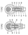
- Figure 1 illustrates the shank 4 and drive means 6 in a first position wherein the drive rod 16 is fitted into the axial recess 14 of the shank 4.
- the shank is introduced into the bore 12 to provide a secure starting location.
- the drive means 6 is then rotated in a clockwise direction to commence screwing of the shank 4 into the bore 12.
- the rotational action is translated to the shank by the engagement of the rod 16 with the walls of the axial recess 14.
- Every size of cable core 10 is required to be clamped to a predesignated torque level to produce the required clamping force and at that torque the shank is required to shear thereby holding the core in this clamped position.
- the torque level at which the shank 4 will shear is determined by the difference between the width of the recess 14 and the outer diameter of the shank 4 and also the material from which the shank is made. The next step is to control the position at which the shear occurs.
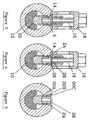
- Figure 4 illustrates the embodiment of Figures 1-3 at a position where the predesignated clamping torque on the core 10 has been reached and shear as indicated by line 26 is about to occur upon continued turning of the drive rod 16.
- the plane of shear is determined by the position of the end 28 of the rod 16 which is in the axial recess 14 of the shank 4 and the position of which is known and fixed due to the support means 18.
- the support means 18 is provided to rest on the connector surface 24 so the position of the end 28 of the drive rod 16 is determined relative to the connector and hence the plane of shear 26 in this embodiment is substantially level with the surface 24 as required.
- the shank 4 when sheared is shown in Figure 5 and the plane of shear 26 is substantially level with the surface 24 as desired.
- the shank is provided with sets of notches 30. The selection of the location of these notches is described in more detail later.
- the notch 30A is positioned foruse when clamping the biggest cable core cross section namely 150mm
- the notch 30B is for the intermediate cross section 120mm
- the notch 30C which in this case is at the shear plane 26, is for inducing shear with a 90mm cross sectional cable core.
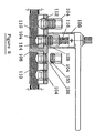
- FIG. 6 there is shown a second embodiment of screw clamping apparatus which comprises the components of the first embodiment but in different forms.
- the apparatus comprises a drive means 106 and a shank 104.
- the figure shows a plurality of shanks 104 at various stages of tightening into bores 112 in an electrical connector 108 to exert clamping forces on cable cores 110.
- the first shank 104 is shown screwed manually into location with the threaded bore 112 but exerts no clamping force on the core 110.
- the second shank is shown with the drive rod 116 engaged in the axial recess 114 of the shank.
- both the drive rod 116 and axial recess 114 have 12 sided cross sections and this allows the drivable engagement between the two which results in the shank being driven into the bore to exert a clamping force on the core. As shown the predetermined turning torque required to be exerted to produce the required clamping force has not been reached hence no shear has occurred.
- the third shank 104 is shown in a sheared form wherein the shear plane 126 is substantially level with the surface of the connector 108.
- the shank shears upon continued turning of the drive rod 116 once the predetermined turning torque has been reached and occurs in the plane of the end 128 of the drive rod 116 and hence the shank shears along the weakening notch 130 which is located on the shank to lie in the required position.
- the fourth shank 104 is shown with the sheared portion removed and illustrates the manner in which no part of the shank protrudes above the level of the plane of the connector 108.
- Figures 7A and 7B show in elevation and plan an embodiment of the drive means 106.
- the drive means includes a polygonal sided drive rod 116 which is substantially surrounded by a support means in the form of a skirt 120.
- the end of the skirt and the drive rod lic in the same plane but it is possible that in certain embodiments and uses the end of the drive rod may be required to be in a different plane to the end of the skirt if a different position of shear plane is required than being level with the skirt seat on the article.
- Both the skirt 120 and drive rod 116 depend from an elongate handle portion 144.
- the handle portion 144 can, in one embodiment, be provided in a fixed position relative to the skirt and drive rod such that the components move together or, alternatively, a conventional ratchet mechanism is incorporated between the handle and the drive rod to allow selected engagement between the handle portion 144 and drive rod 116 and, if required, skirt 120.
- a release rod 146 which is engagable in the axial recess 114 of a sheared shank 104 to allow the sheared shank to be unscrewed from the bore 112.
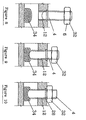
- FIG. 8-10 An example of background art is shown in Figures 8-10 wherein the drive means 6 is in the form of a nut 32 which is threadably mounted on the shank 4.
- the nut is rotatable in conjunction with the shank such that rotation of the same causes the shank to be driven into the bore 12 of the article to pass downwardly, as in figure 9, to exert a clamping force on an article 34.
- Figures 11 and 12 illustrate a further example of background art which again utilises a drive means in the form of a nut 34.
- the nut is mounted on the shank to allow the nut 34 to be slidably axially movable along the shank 4.
- the nut 34 is movable between a first position 36a to a second position 36b.
- the nut is provided with inwardly facing lugs 40 which engage in drive formation means in the form of slots 38 provided in the shank as shown in Figure 12 to allow axial movement of the nut between the first 36a and second 36b positions.
- the lugs 40 also ensure that turning of the nut 34 causes the turning action to be transmitted via the slots 38 to the shank 4 to screw the same into the bore 12.
- the shank is introduced into the bore 12 to provide a secure starting position.
- the nut 34 is moved to a first position 36a and turned to screw the shank 4 into the bore 12 and hence bring the nut in to contact with the surface 24 as shown in Figure 11.
- Continued turning of the nut 34 causes the shank to be continued to be screwed into the bore and as this happens the nut 34 slides upwardly along the slots 38 thereby maintaining the nut 34 in contact with the surface 24.
- continued turning of the nut 34 causes the shank to shear as shown by line 42.
- slots 38 shown are axial it is possible that the slots 38 can be provided in a helical path along the shank 4 to allow the movement of the nut along the shank 4 to be improved during turning of the nut.
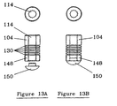
- FIGS 13A and 13B illustrate one embodiment of a shank of the type shown in Figure 6 wherein the shank 104 includes a main portion 148 with an axial recess 114 passing therethrough. On the outer surface of the portion 148, a series of notches 130 are provided. Each notch is provided at a position along the shank which equates with a position at which shear is preferably to occur with regard to different size cable cores and on known connectors. In this case it is required that the notches are positioned such that when the clamping force on a core has reached a predetermined level one of the notches lies in a plane substantially level with the surface of the connector.
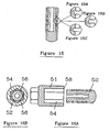
- Figures 15A, 15B and 15C show alternative forms of weakening notches (30,130) which can be provided on a shank.
- the end of the portion 148 which is to contact the article to be clamped is plugged by a plug insert 150 which fits partially into the axial recess 114.
- the plug can also include teeth formed therein to improve the clamping effect and, if used in clamping cable cores, to improve the electrical contact.
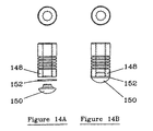
- FIGs 14A and 14B illustrate a shank 104 as in Figures 13A and 13B with an additional component in the form of a washer 152 which fits between the plug insert 150 and the main shank portion 148.
- the outer edge of the washer protrudes sufficiently to ensure that once the shank is screwed into the bore 112 of the article the same will not be unscrewed due to vibration and hence only positive unscrewing action can cause the removal of the shank.
- FIGS 16A and 16B illustrate a further embodiment of the invention wherein the drive means 51 are in the form of a socket 54 which passes over the shank 52.
- the outer surface of the shank 52 has drive formations 56 therealong with which which the inner walls of the socket 54 engage.
- the shank lies within the socket 54 as shown in section in Figure 16B and rotation of the socket causes the shank 52 to be driven into the bore of the article as in the other embodiments.
- the base 58 of the socket meets the article, continued turning of the socket continues to drive the shank 52 into the bore to exert a clamping force until a predetermined turning torque is reached, at which point the shank shears substantially in the plane of the surface of the article and the base 58 of the socket 54.
- the invention provides a screw clamping means for an article comprising a shank which is required to shear once a predetermined turning torque to create a clamping force on the article is reached and drive means for the shank and the two components are provided for relative axial movement to occur such that the plane of shear of the shank is determined by the position of the drive means relative thereto.
- the type of material of the shank, size of article and the characteristics of the article to be clamped can all be used to determine positions for shear along the shank. None of the prior art shear bolts can provide this advantage of controlling the plane of shear to suit the conditions in which the bolts are used.
Landscapes
- Engineering & Computer Science (AREA)
- General Engineering & Computer Science (AREA)
- Mechanical Engineering (AREA)
- Clamps And Clips (AREA)
- Jigs For Machine Tools (AREA)
- Gripping Jigs, Holding Jigs, And Positioning Jigs (AREA)
- Heterocyclic Compounds That Contain Two Or More Ring Oxygen Atoms (AREA)
- Materials For Medical Uses (AREA)
- Polyesters Or Polycarbonates (AREA)
- Heating, Cooling, Or Curing Plastics Or The Like In General (AREA)
- Vehicle Body Suspensions (AREA)
Abstract
Description
- The present invention relates to improvements in clamping screws or shear bolts used to exert a clamping force on an article or articles by the screwing and tightening of the bolt thereon.
- A shank for use to exert such a clamping force according to the preamble of claim 1 is known from US-A-4 053 982.
- As a conventional bolt is tightened to exert a clamping force on an article the torque required to further tighten the bolt increases. When the torque reaches a required level to provide the clamping force the conventional shear bolts are provided with reduced necks and shear at this point such that the head portion is removed. The shearing action of the bolt is commonly succesful but the position of the shear is entirely dependant upon the positioning of the neck.
- This causes problems in many uses and when the article upon which the bolts are used is an electrical cable connector and the articles to be clamped are cable cores, the shank of the bolt which remains can protrude above the surface of the connector. When a connector is used, portions of the two cable cores to be connected are placed in the connector and covered and shear bolts are applied to the connector to be screwed into threaded bores therein to provide a clamping force onto the cores and hold the same in place. When a certain clamping torque is reached the bolt shears at the neck and can leave part of the bolt shank protruding above the surface of the connector. The existence of these protrusions cause particular concern when used with high voltage cable connectors as each of the protrusions can cause what is known as a "corona" effect to occur. A corona effect occurs due to the attraction of high voltage stresses at points which are of a different form than the connector such as the protrusions caused by the sheared bolts. The corona effect leads to the insulation material around and adjacent the protrusions being eroded and destroyed by the high voltage stresses.
- Further problems are caused when it is desired that the connector be coated by a heat shrinkable insulating material or placed in a close fitting sleeve of insulating material to protect the same once the cable cores are in position. The existence of the protrusions on the connector can produce protrusions on the insulating material which arc undesirable or may prevent the fitting of the sleeve.
- In an attempt to overcome these problems it is possible to use packing pieces in conjunction with the bolt when the cable core to be clamped is a relatively small diameter cable compared to the bore of the connector and/or use differing lengths of bolts for each diameter or cable core to be clamped. These are not ideal solutions as the use of additional components adds time to the fitting of the bolts and the range of sizes of bolts which now exist is excessively large and expensive to stock.
- Document US-A-4053982 discloses a dental anchor pin which has a series of weakened sections along the length of the shank and a tool for driving one end of the same into a bore. In this case each part of the shank between the weakened notches is of a length to form a dental pin when the same breaks off when a particular turning force is applied.
- Documents US-A-3937121 and US-A-4659267 both disclose shanks with drive means at one end and two weakened sections spaced along the length of the same, In this case the shank is designed to shear at two locations on the shank, in sequence, as different turning torques are reached. There is no disclosure of the shanks being capable of being used with only one of the two weakened sections shearing.
- DE-A-4113242 illustrates a shank with only one weakened line and therefore the shank does not have a plurality of weakened sections only one of which is desired to shear for the use of the shank.
- The aim of the present invention is to provide a bolt or screw clamping means for use in clamping an article in position, said bolt being provided with means to allow at least a portion to shear off once a predesignated clamping torque is reached and to provide drive means for the same, the said apparatus of a form to allow the position and plane of the shear to be controlled and predicted thereby eliminating the production of protrusions on the surface of the article when the bolt shears.
- The present invention provides a shank according to claim 1.
- According to a first embodiment, the drive means comprises a drive rod of non circular section slidable in a recess axially of the shank whereby the shank is driven by rotation of the drive rod, and a support rotatably supports the drive rod.
- In this embodiment the screw clamping means comprises the threaded shank and the drive means, the drive means including a drive rod for engagement in the axial recess in said shank and a support means, wherein the support means and the drive rod arc rotated together to tighten the shank to bring the support means into contact with the surface of the article adjacent the bore; continued driving of the drive means causes the shank to shear when a predesignated clamping force is reached. Alternatively the support means is held in a fixed position and the drive rod only is driven.
- Typically the shank is caused to shear on a plane substantially defined by the end of the drive rod of the drive means which is positioned in the axial recess of the shank. In this embodiment it is the position of the end of the drive rod which determines the plane of shear of the shank. The position of the end of the rod may be provided to lie directly along the plane of the surface of the article or slightly below the plane but still substantially in the same plane of the surface of the article. This arrangement ensures that the top of the sheared shank does not protrude above the surface of the article and, if the article has a curved surface, that the top of the sheared shank lies on or below the lowest point of the bore edge.
- In one embodiment the support means comprises a plurality of downwardly depending legs the ends of which rest on the article to which the shank is applied.
- Alternatively the support means is a downwardly depending skirt which passes substantially around the drive rod.
- Typically the drive rod and the axial recess of the shank have a polygonal cross section such as, for example, hexagonal or 12 sided.
- Typically the length of the drive rod relative to the article determines the plane of shear upon a predesignated clamping torque level being reached. In all cases the shank will shear in a plane substantially parallel with the end of the drive rod.
- In one embodiment the drive means is provided in the form of a drive socket and said shank is provided on the outer surface thereof with a drive formation for the location of drive means therewith. In one embodiment the drive formation is in the form of a head at the end of the shank which is of polygonal cross section and may also have an aperture for the reception of an Allen key and in an alternative form the engagement portion is formed along part of the length of the outer surface of the shank.
- In one embodiment the axial recess passes through the length of the bolt and the end of the shank is plugged. In one embodiment the plug is formed of brass to provide electrical contact with the clamped article. In one embodiment there is provided an insert which contacts with the bore as it passes therethrough and when the shank is fixed into the bore prevents release of the same due to vibratory action. Typically the insert is a washer held between the plug and the shank at the end thereof.
- The shear torque or clamping force at which the shank is designed to shear is defined by the relative sizes of the axial aperture and outside diameter of the shank and the material from which the shank is manufactured.
- In any embodiment the shank is preferably provided with at least one weakened point along the length thereof to encourage the shank to shear at those points. Typically the weakened points are notches cut into either or both of the outer surface of the shank or along the wall of the axial recess in the shank.
- When used on an electrical cable core connector, the cable cores are clamped in position and the notches are preferably positioned to ensure the shank shears at known positions and these positions can be calculated when used in a connector of known size and for cable cores of known characteristics such that the notches are spaced to ensure that the shank shears in a predicted position in relation to the surface of the article and above the threaded section of the bore. For example, as cables are manufactured in a limited number of defined sizes notches are provided on the shank to match with the length of shank required to provide the necessary clamping force on a particular cable core cross sectional area in a particular connector, and the notches are spaced such that there is always one notch between the end of the drive rod and the start of the threaded section on the bore and it is this notch which shears at a position adjacent the surface of the connector and substantially in the plane of the end of the drive rod to give a smooth and uniform connector surface.
- A further feature of the invention is that if the shank is provided with an axial recess, the recess, which is exposed once the shank has sheared can be re-engaged subsequently by the drive means and rotation of the drive means causes the removal of the shank from the connector. This is of particular advantage where a temporary electrical connection is required to be made and then subsequently changed.
- In one form of the invention there is provided a drive means incorporating a drive rod and a support means wherein said drive means can be used for the driving of a threaded shank into a bore to exert a clamping force, said drive transmitted by the fitting of the drive rod into an axial recess in said shank and the end of the drive rod defines the plane of shear of the shank upon continued turning of the rod once a predesignated clamping force is reached.
- In one embodiment the drive means comprises a drive rod and a support means disposed around said drive rod, said support means and drive rod depending downwardly from a drive handle connected thereto.
- Preferably the drive rod is axially movable relative to the support means, between a first position where the end of the drive rod is substantially level with the end of the support means, for tightening and shearing the shank, and a second position where the end of the drive rod protrudes below the level of the skirt to allow removal of a previously sheared shank. Typically the drive rod is movable between first and second positions along a predetermined path formed in a housing or in the support means mounted on the drive handle.
- In one preferred feature the support means are releasable to allow removal and replacement of the same.
- Preferably the drive means is reusable for the driving and shearing of a plurality of threaded shanks.
- Specific embodiments of the invention are now described with reference to the accompanying drawings, wherein:-
- Figure 1 illustrates a cross sectional elevation of the screw clamping means of the invention in one embodiment in a first position;
- Figure 2 illustrates a cross sectional elevation of the embodiment of Figure 1 in a second position;
- Figure 3 illustrates a cross sectional elevation of the embodiment of Figure 1 in a third position;
- Figure 4 illustrates a cross sectional elevation of the embodiment of Figure 1 at the point of shear;
- Figure 5 illustrates a cross sectional elevation of the embodiment of figure 1 in a final position;
- Figure 6 illustrates a cross sectional elevation of a screw clamping apparatus in a second embodiment with a plurality of threaded shanks in various stages of screwing into bores on an electrical connector;
- Figures 7A and 7B illustrate an elevation and plan of an embodiment of a drive means;
- Figure 8 illustrates an example of background art in a first position;
- Figure 9 illustrates an elevation of the embodiment of Figure 8 in a second position;
- Figure 10 illustrates an elevation of the embodiment of Figure 8 in a third position;
- Figure 11 illustrates a further example of background art at the point of shear;
- Figure 12 illustrates a sectional plan view on AA of the embodiment of Figure 11;
- Figures 13 A and 13B illustrate an embodiment of a shank as used in the apparatus of Figure 6;
- Figures 14A and 14B illustrate an alternative embodiment of a shank;
- Figures 15A, 15B and 15C illustrate forms of weakening points on a shank; and
- Figures 16A and 16B illustrate a further embodiment of the invention.
- Referring firstly to Figure 1 there is shown a first embodiment of the screw clamping means 2 of the invention. The screw clamping means comprises a
shank 4 and drive means 6 for the said shank. In this embodiment theshank 4 is to be inserted into an electriccable core connector 8 to exert a clamping force on thecable core 10. Theshank 4 includes anaxial recess 14 which has a hexagonal cross section and is threaded to be screwed into the threaded bore 12 in theconnector 8. - The drive means 6 comprises a
drive rod 16 with a drive formation in this case in the form of ahead 19 and a support means 18. The drive rod is provided with a hexagonal cross section similar to that of therecess 14 in the shank so that therod 16 fits into and is axially movable in relation to, theaxial recess 14. Rotation of the drive rod causes a screwing drive to be transmitted to theshank 4 via the recess and hence theshank 4 is screwed into thebore 12. The support means 18 comprises a downwardly extendingskirt 20 or legs (not shown). In use, thebottom edges 22 of the skirt rest en thesurface 24 of the connector. The support means 18 can be rotatable with thedrive rod 16 if desired or may be held statonary with thedrive rod 16 rotatable relative thereto. - Figure 1 illustrates the
shank 4 and drive means 6 in a first position wherein thedrive rod 16 is fitted into theaxial recess 14 of theshank 4. Preferably the shank is introduced into thebore 12 to provide a secure starting location. The drive means 6 is then rotated in a clockwise direction to commence screwing of theshank 4 into thebore 12. The rotational action is translated to the shank by the engagement of therod 16 with the walls of theaxial recess 14. - The rotation of the drive means causes the
shank 4 to move into the connector as shown in Figure 2. At this stage the support means 18 has moved down such that thebottom edges 22 now rest on theconnector surface 24 adjacent thebore 12. At this point thedrive rod 16 is prevented from moving any further downwardly with theshank 4 and further turning of the drive means causes continued downward screwing of theshank 4 and produces relative axial movement between therod 16 andshank recess 14 as shown. - Continued turning of the drive means 6 moves the clamping
end 25 of theshank 4 into contact with thecable core 10, causing the same to deform, and then exert a clamping force thereon as shown in Figure 3. - Every size of
cable core 10 is required to be clamped to a predesignated torque level to produce the required clamping force and at that torque the shank is required to shear thereby holding the core in this clamped position. In this invention the torque level at which theshank 4 will shear is determined by the difference between the width of therecess 14 and the outer diameter of theshank 4 and also the material from which the shank is made. The next step is to control the position at which the shear occurs. - Figure 4 illustrates the embodiment of Figures 1-3 at a position where the predesignated clamping torque on the
core 10 has been reached and shear as indicated byline 26 is about to occur upon continued turning of thedrive rod 16. The plane of shear is determined by the position of theend 28 of therod 16 which is in theaxial recess 14 of theshank 4 and the position of which is known and fixed due to the support means 18. The support means 18 is provided to rest on theconnector surface 24 so the position of theend 28 of thedrive rod 16 is determined relative to the connector and hence the plane ofshear 26 in this embodiment is substantially level with thesurface 24 as required. - The
shank 4 when sheared is shown in Figure 5 and the plane ofshear 26 is substantially level with thesurface 24 as desired. To further encourage the plane of shear to be located at a predictable location on the shank, the shank is provided with sets of notches 30. The selection of the location of these notches is described in more detail later. However in Figure 5 thenotch 30A is positioned foruse when clamping the biggest cable core cross section namely 150mm, thenotch 30B is for the intermediate cross section 120mm and thenotch 30C, which in this case is at theshear plane 26, is for inducing shear with a 90mm cross sectional cable core. - Referring now to Figure 6 there is shown a second embodiment of screw clamping apparatus which comprises the components of the first embodiment but in different forms. The apparatus comprises a drive means 106 and a
shank 104. The figure shows a plurality ofshanks 104 at various stages of tightening intobores 112 in anelectrical connector 108 to exert clamping forces oncable cores 110. Commencing from theshank 104 on the left and passing to the right, thefirst shank 104 is shown screwed manually into location with the threaded bore 112 but exerts no clamping force on thecore 110. The second shank is shown with thedrive rod 116 engaged in theaxial recess 114 of the shank. In this case both thedrive rod 116 andaxial recess 114 have 12 sided cross sections and this allows the drivable engagement between the two which results in the shank being driven into the bore to exert a clamping force on the core. As shown the predetermined turning torque required to be exerted to produce the required clamping force has not been reached hence no shear has occurred. - The
third shank 104 is shown in a sheared form wherein theshear plane 126 is substantially level with the surface of theconnector 108. The shank shears upon continued turning of thedrive rod 116 once the predetermined turning torque has been reached and occurs in the plane of theend 128 of thedrive rod 116 and hence the shank shears along the weakeningnotch 130 which is located on the shank to lie in the required position. - The
fourth shank 104 is shown with the sheared portion removed and illustrates the manner in which no part of the shank protrudes above the level of the plane of theconnector 108. - Figures 7A and 7B show in elevation and plan an embodiment of the drive means 106. The drive means includes a polygonal
sided drive rod 116 which is substantially surrounded by a support means in the form of askirt 120. In this embodiment the end of the skirt and the drive rod lic in the same plane but it is possible that in certain embodiments and uses the end of the drive rod may be required to be in a different plane to the end of the skirt if a different position of shear plane is required than being level with the skirt seat on the article. - Both the
skirt 120 and driverod 116 depend from anelongate handle portion 144. Thehandle portion 144 can, in one embodiment, be provided in a fixed position relative to the skirt and drive rod such that the components move together or, alternatively, a conventional ratchet mechanism is incorporated between the handle and the drive rod to allow selected engagement between thehandle portion 144 and driverod 116 and, if required,skirt 120. - On the side of the
handle 144 opposite thedrive rod 116 there is provided arelease rod 146 which is engagable in theaxial recess 114 of a shearedshank 104 to allow the sheared shank to be unscrewed from thebore 112. - An example of background art is shown in Figures 8-10 wherein the drive means 6 is in the form of a
nut 32 which is threadably mounted on theshank 4. In the first instance the nut is rotatable in conjunction with the shank such that rotation of the same causes the shank to be driven into thebore 12 of the article to pass downwardly, as in figure 9, to exert a clamping force on anarticle 34. - 11s the clamping force increases and approaches a predesignated level at which shear of the
shank 4 is required, continued rotation of thenut 32 causes the clamping force to be maintained while at the same time the nut starts to screw down the threaded shank to come to rest on thesurface 28 of the article as shown in Figure 10. In this position thenut 32 is prevented by the article from passing further down theshank 4 and hence continued rotation of thenut 32 causes the shank to shear in a plane defined by theend 28 of the nut and the surface of the article. In this embodiment theend 28 of thenut 32 acts as the determining factor of the position of the plane of shear of theshank 4. - Figures 11 and 12 illustrate a further example of background art which again utilises a drive means in the form of a
nut 34. In this embodiment the nut is mounted on the shank to allow thenut 34 to be slidably axially movable along theshank 4. As sown in Figure 11 thenut 34 is movable between a first position 36a to a second position 36b. The nut is provided with inwardly facinglugs 40 which engage in drive formation means in the form ofslots 38 provided in the shank as shown in Figure 12 to allow axial movement of the nut between the first 36a and second 36b positions. Thelugs 40 also ensure that turning of thenut 34 causes the turning action to be transmitted via theslots 38 to theshank 4 to screw the same into thebore 12. In use the shank is introduced into thebore 12 to provide a secure starting position. Thenut 34 is moved to a first position 36a and turned to screw theshank 4 into thebore 12 and hence bring the nut in to contact with thesurface 24 as shown in Figure 11. Continued turning of thenut 34 causes the shank to be continued to be screwed into the bore and as this happens thenut 34 slides upwardly along theslots 38 thereby maintaining thenut 34 in contact with thesurface 24. When the required clamping force on thecable core 10 has been reached continued turning of thenut 34 causes the shank to shear as shown byline 42. By maintaining the nut in contact withsurface 24 so the plane of shear is located on a plane level with thesurface 24 thereby providing a neat and level sheared shank as required. - Although the
slots 38 shown are axial it is possible that theslots 38 can be provided in a helical path along theshank 4 to allow the movement of the nut along theshank 4 to be improved during turning of the nut. - Figures 13A and 13B illustrate one embodiment of a shank of the type shown in Figure 6 wherein the
shank 104 includes amain portion 148 with anaxial recess 114 passing therethrough. On the outer surface of theportion 148, a series ofnotches 130 are provided. Each notch is provided at a position along the shank which equates with a position at which shear is preferably to occur with regard to different size cable cores and on known connectors. In this case it is required that the notches are positioned such that when the clamping force on a core has reached a predetermined level one of the notches lies in a plane substantially level with the surface of the connector. For example, if the shank shown in Figures 13A and 13B is usable for clamping five standard sized types of cores with known cross sectional areas in a connector as shown in Figure 6, a notch is positioned along the shank at a location for each size. Thus when the turning torque for the required clamping force is reached and shear is to occur a notch will be in position substantially on the plane of the surface of the article and the end of the drive rod to ensure that the shear position and shear surface which occurs is properly located and relatively flat. As there are a limited number of cable core sizes and connector sizes the provision of notches to encourage the shear plane to be induced at these particular locations is practical and advantageous. - Figures 15A, 15B and 15C show alternative forms of weakening notches (30,130) which can be provided on a shank.
- Referring again to Figures 13A and 13B the end of the
portion 148 which is to contact the article to be clamped is plugged by aplug insert 150 which fits partially into theaxial recess 114. The plug can also include teeth formed therein to improve the clamping effect and, if used in clamping cable cores, to improve the electrical contact. - Figures 14A and 14B illustrate a
shank 104 as in Figures 13A and 13B with an additional component in the form of awasher 152 which fits between theplug insert 150 and themain shank portion 148. The outer edge of the washer protrudes sufficiently to ensure that once the shank is screwed into thebore 112 of the article the same will not be unscrewed due to vibration and hence only positive unscrewing action can cause the removal of the shank. - Figures 16A and 16B illustrate a further embodiment of the invention wherein the drive means 51 are in the form of a
socket 54 which passes over theshank 52. The outer surface of theshank 52 hasdrive formations 56 therealong with which which the inner walls of thesocket 54 engage. When engaged the shank lies within thesocket 54 as shown in section in Figure 16B and rotation of the socket causes theshank 52 to be driven into the bore of the article as in the other embodiments. When thebase 58 of the socket meets the article, continued turning of the socket continues to drive theshank 52 into the bore to exert a clamping force until a predetermined turning torque is reached, at which point the shank shears substantially in the plane of the surface of the article and thebase 58 of thesocket 54. - The invention provides a screw clamping means for an article comprising a shank which is required to shear once a predetermined turning torque to create a clamping force on the article is reached and drive means for the shank and the two components are provided for relative axial movement to occur such that the plane of shear of the shank is determined by the position of the drive means relative thereto. The type of material of the shank, size of article and the characteristics of the article to be clamped can all be used to determine positions for shear along the shank. None of the prior art shear bolts can provide this advantage of controlling the plane of shear to suit the conditions in which the bolts are used.
Claims (8)
- A shank (4,104,52) for use to exert a clamping force on a first article (10, 110) within a second article (8,108), said shank including a drive formation (14, 114, 56) for the location of drive means therewith, a threaded section along at least part of the outer wall and a series of spaced apart weakened sections (30,130) along the length thereof to encourage the shank to shear at one of said weakened sections when a predetermined clamping force is reached, and characterised in that the weakened sections are located along that part of the shank along which the drive formation (14,114,56) is formed and each weakened section is formed so that one of the spaced apart weakened sections will shear in the plane of the surface of the second article (8, 108) when a predetermined clamping force on the first article (10, 110) is reached and no further turning of the shank is thereafter required.
- A shank according to claim 1 characterised in that drive means (6,106,51) are provided to drive the screw shank, said drive means comprising a drive rod (16, 116) said drive rod of non-circular section and slidable in a drive formation in the form of a recess (14,114) axially of the screw shank (4,104,52) whereby the screw shank (4,104,52) is driven by rotation of the drive rod (16,116).
- A shank according to any of the preceding claims characterised in that the shank has located toward the end of the same an insert (150) which contacts a threaded bore into which the same is driven, to prevent release of the shank from the first article (10, 110) due to vibratory effect once the same has been inserted into the bore.
- A shank according to claim 1 characterised in that the weakened sections are of a form to encourage the shank to shear in a position on the shank equivalent to a required clamping force on any of a range of articles of known dimension (10, 110).
- A shank according to claim 1 characterised in that the shank is driven into a bore provided in an electrical connector to exert a clamping effect on any of a range of electrical conductors and the weakened sections are positioned along the shank, and are of a form to encourage the shank to shear in the plane of the surface of the connector when the required turning torque is reached for any of the range of the conductors in the connector.
- A shank according to claim 1 characterised in that the weakened sections are formed on the external wall of the shank.
- A shank according to claim 1 characterised in that the weakened sections are spaced in relation to a range of predesignated articles to be clamped and selectively shaped and formed along the length of the shank.
- A shank according to claim 7 characterised in that each of the weakened sections in a series is positioned and shaped in correspondence with a particular first article (10, 110) in the series of articles which is to be clamped so as to encourage the appropriate weakened section which lies in the plane of the surface of the second article (8, 108), to shear at the required clamping force for the first article.
Applications Claiming Priority (3)
| Application Number | Priority Date | Filing Date | Title |
|---|---|---|---|
| GB9404979A GB9404979D0 (en) | 1994-03-15 | 1994-03-15 | Improvements relating to clamping screws |
| GB9404979 | 1994-03-15 | ||
| PCT/GB1994/002608 WO1995025229A1 (en) | 1994-03-15 | 1994-11-29 | Improvements relating to clamping screws |
Publications (2)
| Publication Number | Publication Date |
|---|---|
| EP0750723A1 EP0750723A1 (en) | 1997-01-02 |
| EP0750723B1 true EP0750723B1 (en) | 2006-12-27 |
Family
ID=10751839
Family Applications (1)
| Application Number | Title | Priority Date | Filing Date |
|---|---|---|---|
| EP95902186A Expired - Lifetime EP0750723B1 (en) | 1994-03-15 | 1994-11-29 | Improvements relating to clamping screws |
Country Status (8)
| Country | Link |
|---|---|
| US (2) | US6209424B1 (en) |
| EP (1) | EP0750723B1 (en) |
| AT (1) | ATE349626T1 (en) |
| AU (1) | AU704169B2 (en) |
| DE (1) | DE69434899T2 (en) |
| ES (1) | ES2275266T3 (en) |
| GB (2) | GB9404979D0 (en) |
| WO (1) | WO1995025229A1 (en) |
Cited By (5)
| Publication number | Priority date | Publication date | Assignee | Title |
|---|---|---|---|---|
| EP2071201A1 (en) | 2007-12-11 | 2009-06-17 | Nexans | Shear screw |
| EP2381534A1 (en) | 2010-04-20 | 2011-10-26 | Nexans | Clamping screw |
| EP2381535A1 (en) | 2010-04-26 | 2011-10-26 | Nexans | Assembly for fixing an electric conductor in a clamp |
| EP2498338A1 (en) | 2011-03-11 | 2012-09-12 | Nexans | Clamping screw |
| EP3492757B1 (en) | 2017-11-29 | 2023-07-26 | Ensto Oy | Shearing screw |
Families Citing this family (44)
| Publication number | Priority date | Publication date | Assignee | Title |
|---|---|---|---|---|
| GB9404979D0 (en) * | 1994-03-15 | 1994-04-27 | Sicame Electrical Dev Ltd | Improvements relating to clamping screws |
| EP0692643B2 (en) † | 1994-07-15 | 2005-03-30 | ARCUS ELEKROTECHNIK Alois Schiffmann GmbH | Shearable screw |
| GB9507240D0 (en) * | 1995-04-07 | 1995-05-31 | B & H Nottingham Ltd | Fastener |
| ES2157105T3 (en) | 1998-08-18 | 2001-08-01 | Petri Gerhard Gmbh & Co Kg | SCREW HEAD SCREW. |
| GB9902358D0 (en) * | 1999-02-04 | 1999-03-24 | B & H Nottingham Ltd | Electrical connector |
| FR2796209B1 (en) * | 1999-07-06 | 2001-08-24 | Michel Scola | SELF-STRIPING CONNECTOR FOR INSULATED ELECTRICAL CABLES |
| DE19960198A1 (en) * | 1999-12-14 | 2001-06-28 | Pfisterer Kontaktsyst Gmbh | Locking screw device with distancing element and screw connecting lock for fixing an object includes a setscrew with a tool holder, predetermined breaking points and a distancing element in the tool holder. |
| DE10234460B3 (en) * | 2002-06-27 | 2004-03-18 | Arcus Elektrotechnik Alois Schiffmann Gmbh | Multiple shear screw |
| DE10312147A1 (en) * | 2003-03-17 | 2004-10-07 | Pfisterer Kontaktsysteme Gmbh & Co. Kg | Fasteners, in particular a tear-off screw, and associated screw connection clamp |
| US7104832B2 (en) | 2004-08-05 | 2006-09-12 | 3M Innovative Properties Company | Modular electrical connector and method of using |
| US7090544B2 (en) | 2004-08-05 | 2006-08-15 | 3M Innovative Properties Company | Modular electrical connector and method of using |
| FI119198B (en) * | 2005-05-16 | 2008-08-29 | Ensto Sekko Oy | Screw that breaks at shaft |
| BRPI0703433B1 (en) * | 2006-03-08 | 2018-05-08 | Ridelin Sl | screws for electrical connectors |
| KR101366943B1 (en) | 2006-05-05 | 2014-02-24 | 쓰리엠 이노베이티브 프로퍼티즈 컴파니 | Tubular terminal for a cable |
| DE102006048177A1 (en) * | 2006-10-10 | 2008-04-24 | Pfisterer Kontaktsysteme Gmbh & Co. Kg | Fastening means, in particular tear-off screw, with separable clamping section |
| ES2394511T3 (en) * | 2006-12-12 | 2013-02-01 | Nexans | Fixing device suitable for shearing with force transmission element |
| US7670153B2 (en) * | 2007-09-10 | 2010-03-02 | Burndy Technology Llc | Electrical connector |
| DE102007059213A1 (en) | 2007-12-08 | 2009-06-10 | Bayer Industry Services Gmbh & Co. Ohg | Fixing unit for removable article at fixed retaining fixture in clean room arrangement, has C-shaped holder connected with carrier element and comprising U-shaped and S-shaped clamps for reversible fixing at fixture |
| GB2458644B (en) * | 2008-03-25 | 2011-12-21 | Business Lines Ltd | Rotation indicator |
| US7915530B2 (en) * | 2008-04-01 | 2011-03-29 | Thomas & Betts Corporation | Torque limiting device for insulated plug |
| DE102009009793A1 (en) | 2009-02-20 | 2010-08-26 | Südkabel GmbH | Cable connector for tearing head screw, has pipe coupling, in which internal space of cable end is inserted and screw, by which cable end is clamped in pipe coupling |
| EP2322816A1 (en) * | 2009-11-17 | 2011-05-18 | Nexans | Clamping screw |
| ES2355994A1 (en) * | 2010-03-11 | 2011-04-01 | Sofamel, S.A. | Screw for electrical connector. (Machine-translation by Google Translate, not legally binding) |
| US8425265B2 (en) | 2011-02-08 | 2013-04-23 | Nexans | Arrangement with a clamp of metal constructed as a pipe piece |
| EP2498339B1 (en) * | 2011-03-11 | 2013-12-18 | Nexans | Assembly with a terminal and at least one clamping screw |
| AU2012200645A1 (en) * | 2011-02-08 | 2012-08-23 | Nexans | Arrangement with a Clamp of Metal Constructed as a Pipe Piece |
| PL2608338T3 (en) | 2011-12-21 | 2014-04-30 | 3M Innovative Properties Co | Terminal connection device for a power cable |
| CA2916569A1 (en) | 2013-06-26 | 2014-12-31 | 3M Innovative Properties Company | Power cable terminal connection device |
| US9366282B2 (en) * | 2013-09-06 | 2016-06-14 | Thomas & Betts International Llc | Torque controlling break screw |
| US9929477B2 (en) * | 2015-04-30 | 2018-03-27 | Ilsco Corporation | Torque limited screw for electrical connector |
| US9956071B2 (en) * | 2015-09-29 | 2018-05-01 | Depuy Mitek, Llc | Adjustable length surgical screws and inserters for adjustable length surgical screws |
| WO2018102118A1 (en) | 2016-11-30 | 2018-06-07 | 3M Innovative Properties Company | Shear bolt |
| FI3388697T4 (en) | 2017-04-13 | 2025-11-26 | Tyco Electronics Simel | Shearable fastener bolt and method for clamping electric wires, and electric connector comprising a zero-protrusion shearable fastener |
| FI127655B (en) | 2017-09-08 | 2018-11-30 | Ensto Oy | Shearing screw |
| EP3499646B1 (en) | 2017-12-14 | 2023-03-08 | Tyco Electronics Raychem GmbH | Electrical connector and connector system using the same |
| US10167891B1 (en) * | 2018-03-08 | 2019-01-01 | International Business Machines Corporation | Self-reporting, grounded nut-clip |
| US11326639B1 (en) | 2018-09-24 | 2022-05-10 | Richards Mfg. Co., A New Jersey Limited Partnership | Range taking shear bolts and drive tools |
| IT201900001625A1 (en) * | 2019-02-05 | 2020-08-05 | Cembre Spa | Torsion shear screw for electrical joints |
| US11276946B2 (en) * | 2019-03-21 | 2022-03-15 | TE Connectivity Services Gmbh | Cable connector system and a method of connecting electrical cables |
| EP3792509B1 (en) * | 2019-09-10 | 2023-08-30 | Tyco Electronics SIMEL | Torque-limiting nut for a break-off bolt |
| CA3174430A1 (en) * | 2020-04-01 | 2021-10-07 | Dana Khalid Saeed | Breakaway threaded fasteners and electrical connectors having such fasteners |
| DE102020112157A1 (en) * | 2020-05-06 | 2021-11-11 | Voith Patent Gmbh | Form-fitting component connection and energy dissipation device of a rail vehicle coupling with such a component connection |
| US12215726B2 (en) * | 2021-04-05 | 2025-02-04 | Richards Mfg. Co., A New Jersey Limited Partnership | Range taking shear bolts and drive tools |
| WO2023196797A1 (en) | 2022-04-07 | 2023-10-12 | Hubbell Incorporated | Breakaway threaded fasteners |
Family Cites Families (17)
| Publication number | Priority date | Publication date | Assignee | Title |
|---|---|---|---|---|
| US3284825A (en) * | 1966-02-25 | 1966-11-15 | Herbert C Brauchla | Method of forming screw strip |
| US3763725A (en) * | 1971-07-14 | 1973-10-09 | Textron Inc | Threaded fastener device with torque control and driver therefore |
| CH535391A (en) * | 1971-07-20 | 1973-03-31 | Brander Hans | Process for the production of expansion shafts on bolt-like connecting elements |
| US3928915A (en) * | 1972-03-31 | 1975-12-30 | Irving A Ellman | Tooth anchoring means and method |
| US3865007A (en) * | 1973-07-30 | 1975-02-11 | Square D Co | Torque determining allen screw |
| US4179955A (en) | 1974-03-13 | 1979-12-25 | Mitsubishi Denki Kabushiki Kaisha | Power wrench |
| US3937121A (en) | 1975-04-14 | 1976-02-10 | Pitney-Bowes, Inc. | Double break-off screw |
| US4053982A (en) * | 1976-03-23 | 1977-10-18 | Bernard Weissman | Dental anchor |
| US4742735A (en) * | 1977-11-09 | 1988-05-10 | Vsi Corporation | Driver for a lobed collar |
| JPS61129243A (en) * | 1984-11-29 | 1986-06-17 | Nippon Steel Corp | Production of prefastenable torque-shear bolt |
| GB2220721B (en) * | 1988-07-11 | 1992-02-12 | Austin Rover Group | A method of making threaded fasteners |
| US5182973A (en) * | 1988-10-13 | 1993-02-02 | Martindell J Richard | Depth locator apparatus for insert bit holders |
| DE4113242C2 (en) | 1991-04-23 | 2003-12-24 | Arcus Elektrotech | shearbolt |
| US5520075A (en) * | 1991-06-07 | 1996-05-28 | Barmore; Thomas C. | Socket wrench set and fastener |
| US5372466A (en) * | 1993-04-16 | 1994-12-13 | O'berry; Jon L. | Device to eliminate squeaks in floors and method |
| US5592861A (en) * | 1993-06-04 | 1997-01-14 | Barmore; Thomas C. | Socket wrench set |
| GB9404979D0 (en) * | 1994-03-15 | 1994-04-27 | Sicame Electrical Dev Ltd | Improvements relating to clamping screws |
-
1994
- 1994-03-15 GB GB9404979A patent/GB9404979D0/en active Pending
- 1994-11-03 GB GB9422184A patent/GB2281599B/en not_active Expired - Lifetime
- 1994-11-24 US US08/714,134 patent/US6209424B1/en not_active Expired - Lifetime
- 1994-11-29 AT AT95902186T patent/ATE349626T1/en active
- 1994-11-29 ES ES95902186T patent/ES2275266T3/en not_active Expired - Lifetime
- 1994-11-29 AU AU11128/95A patent/AU704169B2/en not_active Expired
- 1994-11-29 DE DE69434899T patent/DE69434899T2/en not_active Expired - Lifetime
- 1994-11-29 WO PCT/GB1994/002608 patent/WO1995025229A1/en not_active Ceased
- 1994-11-29 EP EP95902186A patent/EP0750723B1/en not_active Expired - Lifetime
-
2001
- 2001-01-16 US US09/761,440 patent/US6321624B1/en not_active Expired - Lifetime
Cited By (5)
| Publication number | Priority date | Publication date | Assignee | Title |
|---|---|---|---|---|
| EP2071201A1 (en) | 2007-12-11 | 2009-06-17 | Nexans | Shear screw |
| EP2381534A1 (en) | 2010-04-20 | 2011-10-26 | Nexans | Clamping screw |
| EP2381535A1 (en) | 2010-04-26 | 2011-10-26 | Nexans | Assembly for fixing an electric conductor in a clamp |
| EP2498338A1 (en) | 2011-03-11 | 2012-09-12 | Nexans | Clamping screw |
| EP3492757B1 (en) | 2017-11-29 | 2023-07-26 | Ensto Oy | Shearing screw |
Also Published As
| Publication number | Publication date |
|---|---|
| US6209424B1 (en) | 2001-04-03 |
| ATE349626T1 (en) | 2007-01-15 |
| GB9422184D0 (en) | 1994-12-21 |
| ES2275266T3 (en) | 2007-06-01 |
| US6321624B1 (en) | 2001-11-27 |
| GB9404979D0 (en) | 1994-04-27 |
| GB2281599B (en) | 1996-04-10 |
| DE69434899D1 (en) | 2007-02-08 |
| DE69434899T2 (en) | 2007-05-10 |
| GB2281599A (en) | 1995-03-08 |
| AU1112895A (en) | 1995-10-03 |
| AU704169B2 (en) | 1999-04-15 |
| WO1995025229A1 (en) | 1995-09-21 |
| EP0750723A1 (en) | 1997-01-02 |
Similar Documents
| Publication | Publication Date | Title |
|---|---|---|
| EP0750723B1 (en) | Improvements relating to clamping screws | |
| US4823650A (en) | Power driven wire nut wrench | |
| AU697922B2 (en) | Fastener | |
| EP1244877B1 (en) | Anchoring element | |
| KR19980702843A (en) | Bone screws | |
| US3787948A (en) | Wire nut wrench | |
| JP3516773B2 (en) | Electrical equipment | |
| GB2295871A (en) | Screw shank for clamping | |
| EP1228553B1 (en) | Insulation-piercing fastener | |
| EP1100390B1 (en) | Tool and method for shearing bolts | |
| EP3492758B1 (en) | Shearing screw | |
| DE19960198A1 (en) | Locking screw device with distancing element and screw connecting lock for fixing an object includes a setscrew with a tool holder, predetermined breaking points and a distancing element in the tool holder. | |
| US7915530B2 (en) | Torque limiting device for insulated plug | |
| US8006723B2 (en) | Conductor loop-forming tool | |
| GB2210124A (en) | Tamper-proof fastening | |
| GB2234695A (en) | Screwdriver accessory | |
| WO2019203809A1 (en) | Screw insert and tool for use screw insert | |
| US20080254667A1 (en) | Electrical Connector | |
| GB2389158A (en) | Anchorage | |
| WO2020131242A1 (en) | Screw insert and tool for use with screw insert | |
| KR19990020329U (en) | Depth adjustment socket |
Legal Events
| Date | Code | Title | Description |
|---|---|---|---|
| PUAI | Public reference made under article 153(3) epc to a published international application that has entered the european phase |
Free format text: ORIGINAL CODE: 0009012 |
|
| 17P | Request for examination filed |
Effective date: 19960917 |
|
| AK | Designated contracting states |
Kind code of ref document: A1 Designated state(s): AT BE CH DE DK ES FR GB GR IE IT LI LU MC NL PT SE |
|
| 17Q | First examination report despatched |
Effective date: 19970708 |
|
| APAB | Appeal dossier modified |
Free format text: ORIGINAL CODE: EPIDOS NOAPE |
|
| APAB | Appeal dossier modified |
Free format text: ORIGINAL CODE: EPIDOS NOAPE |
|
| APAD | Appeal reference recorded |
Free format text: ORIGINAL CODE: EPIDOS REFNE |
|
| APCB | Communication from the board of appeal sent |
Free format text: ORIGINAL CODE: EPIDOS OBAPE |
|
| APCB | Communication from the board of appeal sent |
Free format text: ORIGINAL CODE: EPIDOS OBAPE |
|
| APCB | Communication from the board of appeal sent |
Free format text: ORIGINAL CODE: EPIDOS OBAPE |
|
| APCB | Communication from the board of appeal sent |
Free format text: ORIGINAL CODE: EPIDOS OBAPE |
|
| RAP1 | Party data changed (applicant data changed or rights of an application transferred) |
Owner name: SICAME ELECTRICAL DEVELOPMENTS LTD |
|
| APAB | Appeal dossier modified |
Free format text: ORIGINAL CODE: EPIDOS NOAPE |
|
| APBT | Appeal procedure closed |
Free format text: ORIGINAL CODE: EPIDOSNNOA9E |
|
| APBV | Interlocutory revision of appeal recorded |
Free format text: ORIGINAL CODE: EPIDOSNIRAPE |
|
| APBV | Interlocutory revision of appeal recorded |
Free format text: ORIGINAL CODE: EPIDOSNIRAPE |
|
| APAF | Appeal reference modified |
Free format text: ORIGINAL CODE: EPIDOSCREFNE |
|
| GRAP | Despatch of communication of intention to grant a patent |
Free format text: ORIGINAL CODE: EPIDOSNIGR1 |
|
| GRAS | Grant fee paid |
Free format text: ORIGINAL CODE: EPIDOSNIGR3 |
|
| GRAA | (expected) grant |
Free format text: ORIGINAL CODE: 0009210 |
|
| STAA | Information on the status of an ep patent application or granted ep patent |
Free format text: STATUS: THE PATENT HAS BEEN GRANTED |
|
| AK | Designated contracting states |
Kind code of ref document: B1 Designated state(s): AT BE CH DE DK ES FR GB GR IE IT LI LU MC NL PT SE |
|
| PG25 | Lapsed in a contracting state [announced via postgrant information from national office to epo] |
Ref country code: NL Free format text: LAPSE BECAUSE OF FAILURE TO SUBMIT A TRANSLATION OF THE DESCRIPTION OR TO PAY THE FEE WITHIN THE PRESCRIBED TIME-LIMIT Effective date: 20061227 Ref country code: LI Free format text: LAPSE BECAUSE OF FAILURE TO SUBMIT A TRANSLATION OF THE DESCRIPTION OR TO PAY THE FEE WITHIN THE PRESCRIBED TIME-LIMIT Effective date: 20061227 Ref country code: DK Free format text: LAPSE BECAUSE OF FAILURE TO SUBMIT A TRANSLATION OF THE DESCRIPTION OR TO PAY THE FEE WITHIN THE PRESCRIBED TIME-LIMIT Effective date: 20061227 Ref country code: CH Free format text: LAPSE BECAUSE OF FAILURE TO SUBMIT A TRANSLATION OF THE DESCRIPTION OR TO PAY THE FEE WITHIN THE PRESCRIBED TIME-LIMIT Effective date: 20061227 Ref country code: BE Free format text: LAPSE BECAUSE OF FAILURE TO SUBMIT A TRANSLATION OF THE DESCRIPTION OR TO PAY THE FEE WITHIN THE PRESCRIBED TIME-LIMIT Effective date: 20061227 |
|
| REG | Reference to a national code |
Ref country code: GB Ref legal event code: FG4D |
|
| REG | Reference to a national code |
Ref country code: IE Ref legal event code: FG4D |
|
| REF | Corresponds to: |
Ref document number: 69434899 Country of ref document: DE Date of ref document: 20070208 Kind code of ref document: P |
|
| REG | Reference to a national code |
Ref country code: SE Ref legal event code: TRGR |
|
| ET | Fr: translation filed | ||
| PG25 | Lapsed in a contracting state [announced via postgrant information from national office to epo] |
Ref country code: PT Free format text: LAPSE BECAUSE OF FAILURE TO SUBMIT A TRANSLATION OF THE DESCRIPTION OR TO PAY THE FEE WITHIN THE PRESCRIBED TIME-LIMIT Effective date: 20070528 |
|
| NLV1 | Nl: lapsed or annulled due to failure to fulfill the requirements of art. 29p and 29m of the patents act | ||
| REG | Reference to a national code |
Ref country code: ES Ref legal event code: FG2A Ref document number: 2275266 Country of ref document: ES Kind code of ref document: T3 |
|
| REG | Reference to a national code |
Ref country code: CH Ref legal event code: PL |
|
| PLBI | Opposition filed |
Free format text: ORIGINAL CODE: 0009260 |
|
| PLAX | Notice of opposition and request to file observation + time limit sent |
Free format text: ORIGINAL CODE: EPIDOSNOBS2 |
|
| 26 | Opposition filed |
Opponent name: NEXANS Effective date: 20070926 |
|
| PLAZ | Examination of admissibility of opposition: despatch of communication + time limit |
Free format text: ORIGINAL CODE: EPIDOSNOPE2 |
|
| PLBG | Opposition deemed not to have been filed |
Free format text: ORIGINAL CODE: 0009274 |
|
| PG25 | Lapsed in a contracting state [announced via postgrant information from national office to epo] |
Ref country code: GR Free format text: LAPSE BECAUSE OF FAILURE TO SUBMIT A TRANSLATION OF THE DESCRIPTION OR TO PAY THE FEE WITHIN THE PRESCRIBED TIME-LIMIT Effective date: 20070328 |
|
| 26D | Opposition deemed not to have been filed |
Opponent name: NEXANS Effective date: 20080312 |
|
| PG25 | Lapsed in a contracting state [announced via postgrant information from national office to epo] |
Ref country code: MC Free format text: LAPSE BECAUSE OF NON-PAYMENT OF DUE FEES Effective date: 20071130 |
|
| PLAB | Opposition data, opponent's data or that of the opponent's representative modified |
Free format text: ORIGINAL CODE: 0009299OPPO |
|
| PG25 | Lapsed in a contracting state [announced via postgrant information from national office to epo] |
Ref country code: IE Free format text: LAPSE BECAUSE OF NON-PAYMENT OF DUE FEES Effective date: 20071129 |
|
| PG25 | Lapsed in a contracting state [announced via postgrant information from national office to epo] |
Ref country code: LU Free format text: LAPSE BECAUSE OF NON-PAYMENT OF DUE FEES Effective date: 20071129 |
|
| PLAB | Opposition data, opponent's data or that of the opponent's representative modified |
Free format text: ORIGINAL CODE: 0009299OPPO |
|
| REG | Reference to a national code |
Ref country code: DE Ref legal event code: R082 Ref document number: 69434899 Country of ref document: DE Representative=s name: EISENFUEHR SPEISER PATENTANWAELTE RECHTSANWAEL, DE Ref country code: DE Ref legal event code: R082 Ref document number: 69434899 Country of ref document: DE Representative=s name: EISENFUEHR, SPEISER & PARTNER, DE |
|
| PGFP | Annual fee paid to national office [announced via postgrant information from national office to epo] |
Ref country code: SE Payment date: 20130923 Year of fee payment: 20 |
|
| PGFP | Annual fee paid to national office [announced via postgrant information from national office to epo] |
Ref country code: GB Payment date: 20130916 Year of fee payment: 20 |
|
| PGFP | Annual fee paid to national office [announced via postgrant information from national office to epo] |
Ref country code: AT Payment date: 20130920 Year of fee payment: 20 Ref country code: FR Payment date: 20130920 Year of fee payment: 20 Ref country code: DE Payment date: 20130920 Year of fee payment: 20 |
|
| PGFP | Annual fee paid to national office [announced via postgrant information from national office to epo] |
Ref country code: ES Payment date: 20130920 Year of fee payment: 20 Ref country code: IT Payment date: 20131129 Year of fee payment: 20 |
|
| REG | Reference to a national code |
Ref country code: DE Ref legal event code: R071 Ref document number: 69434899 Country of ref document: DE |
|
| REG | Reference to a national code |
Ref country code: DE Ref legal event code: R071 Ref document number: 69434899 Country of ref document: DE |
|
| REG | Reference to a national code |
Ref country code: GB Ref legal event code: PE20 Expiry date: 20141128 |
|
| REG | Reference to a national code |
Ref country code: AT Ref legal event code: MK07 Ref document number: 349626 Country of ref document: AT Kind code of ref document: T Effective date: 20141129 |
|
| PG25 | Lapsed in a contracting state [announced via postgrant information from national office to epo] |
Ref country code: GB Free format text: LAPSE BECAUSE OF EXPIRATION OF PROTECTION Effective date: 20141128 |
|
| REG | Reference to a national code |
Ref country code: SE Ref legal event code: EUG |
|
| REG | Reference to a national code |
Ref country code: ES Ref legal event code: FD2A Effective date: 20150327 |
|
| PG25 | Lapsed in a contracting state [announced via postgrant information from national office to epo] |
Ref country code: ES Free format text: LAPSE BECAUSE OF EXPIRATION OF PROTECTION Effective date: 20141130 |
|
| REG | Reference to a national code |
Ref country code: DE Ref legal event code: R100 Ref document number: 69434899 Country of ref document: DE |
|
| PLAB | Opposition data, opponent's data or that of the opponent's representative modified |
Free format text: ORIGINAL CODE: 0009299OPPO |
|
| R26D | Opposition deemed not to have been filed (corrected) |
Opponent name: NEXANS Effective date: 20080623 |