EP0750931A2 - Wet dust collecting apparatus - Google Patents
Wet dust collecting apparatus Download PDFInfo
- Publication number
- EP0750931A2 EP0750931A2 EP96304791A EP96304791A EP0750931A2 EP 0750931 A2 EP0750931 A2 EP 0750931A2 EP 96304791 A EP96304791 A EP 96304791A EP 96304791 A EP96304791 A EP 96304791A EP 0750931 A2 EP0750931 A2 EP 0750931A2
- Authority
- EP
- European Patent Office
- Prior art keywords
- mist
- dust
- suction passage
- collecting apparatus
- dust collecting
- Prior art date
- Legal status (The legal status is an assumption and is not a legal conclusion. Google has not performed a legal analysis and makes no representation as to the accuracy of the status listed.)
- Granted
Links
- 239000000428 dust Substances 0.000 title claims abstract description 114
- 239000003595 mist Substances 0.000 claims abstract description 88
- XLYOFNOQVPJJNP-UHFFFAOYSA-N water Substances O XLYOFNOQVPJJNP-UHFFFAOYSA-N 0.000 claims abstract description 53
- 238000004891 communication Methods 0.000 claims abstract description 4
- 238000005192 partition Methods 0.000 claims description 9
- 238000013459 approach Methods 0.000 claims description 3
- 238000011144 upstream manufacturing Methods 0.000 claims description 2
- 238000003754 machining Methods 0.000 abstract description 11
- 239000003517 fume Substances 0.000 abstract description 9
- 238000010276 construction Methods 0.000 description 4
- 230000001877 deodorizing effect Effects 0.000 description 3
- 229910000838 Al alloy Inorganic materials 0.000 description 1
- 238000002485 combustion reaction Methods 0.000 description 1
- 230000007797 corrosion Effects 0.000 description 1
- 238000005260 corrosion Methods 0.000 description 1
- 230000007423 decrease Effects 0.000 description 1
- 230000003247 decreasing effect Effects 0.000 description 1
- 238000007599 discharging Methods 0.000 description 1
- 230000000694 effects Effects 0.000 description 1
- 238000003912 environmental pollution Methods 0.000 description 1
- 238000007667 floating Methods 0.000 description 1
- 239000000463 material Substances 0.000 description 1
- 238000011084 recovery Methods 0.000 description 1
- 230000029058 respiratory gaseous exchange Effects 0.000 description 1
- 238000007711 solidification Methods 0.000 description 1
- 230000008023 solidification Effects 0.000 description 1
- 230000000087 stabilizing effect Effects 0.000 description 1
- 239000010935 stainless steel Substances 0.000 description 1
- 229910001220 stainless steel Inorganic materials 0.000 description 1
Images


Classifications
-
- B—PERFORMING OPERATIONS; TRANSPORTING
- B01—PHYSICAL OR CHEMICAL PROCESSES OR APPARATUS IN GENERAL
- B01D—SEPARATION
- B01D47/00—Separating dispersed particles from gases, air or vapours by liquid as separating agent
- B01D47/02—Separating dispersed particles from gases, air or vapours by liquid as separating agent by passing the gas or air or vapour over or through a liquid bath
- B01D47/024—Separating dispersed particles from gases, air or vapours by liquid as separating agent by passing the gas or air or vapour over or through a liquid bath by impinging the gas to be cleaned essentially in a perpendicular direction onto the liquid surface
-
- B—PERFORMING OPERATIONS; TRANSPORTING
- B01—PHYSICAL OR CHEMICAL PROCESSES OR APPARATUS IN GENERAL
- B01D—SEPARATION
- B01D50/00—Combinations of methods or devices for separating particles from gases or vapours
- B01D50/40—Combinations of devices covered by groups B01D45/00 and B01D47/00
Definitions
- the present invention relates to wet dust collecting apparatus, such as wet dust collecting apparatus for collecting fume dust generated when machining with a laser and plasma machine or cold dust generated in large quantities with a shotblasi, sanding machine or the like.
- fume dust is generated having a very high temperature of 200-300°C, and as an apparatus for collecting such fume dust there have been so far known a dust collecting apparatus of a dry filter type and a wet dust collecting apparatus.
- the wet dust collecting apparatus is advantageous in case of machining with a laser and plasma machine.
- Such conventional wet dust collecting apparatus is generally constructed such that a mist generator is arranged in the dust collecting apparatus. The hot dust is sucked in a mist atmosphere generated by the mist generator and adheres to the mist, to be cooled and then collected with a filter.
- Such conventional wet dust collecting apparatus provided with the mist generator involves a problem that, since the mist generator must be separately provided in the dust collecting apparatus, construction of the latter apparatus becomes complicated and large-sized and increases the construction cost.
- wet dust collecting apparatus simply constructed, small-sized and of low cost that is capable of introducing hot dust generated when machining with a laser and plasma machine or cold dust generated in large quantities with a shotblast, sanding machine and the like into mist generated using the suction pressure for the dust so as to efficiently collect it without separately providing a mist generator, capable of unmanned operation without any risk of causing fire, nevertheless enabling easy posttreatment and stabilizing the machining precision and further has deodorizing function.
- a wet dust collecting apparatus comprises a housing, a suction passage formed in the housing for sucking dust, a water tub arranged in the housing, a mist room formed in upper portion of the water tub, said mist room being defined by a partition plate arranged downstream of the sucking passage, a dust filter arranged downstream of the mist room, a fan for sucking hot dust from the suction passage through the mist room to the filter, and a comb-toothed mist generator arranged at a communicating portion between the suction passage and the mist room, the arrangement being such that dust-containing air sucked in the suction passage is blown against the mist generator so as to vibrate the water surface with high speed thereby generating mist in the mist room, the hot dust is adsorbed to the mist and cooled thereby, the hot dust containing mist is collected by the dust filter thereby separating the dust and water content.
- the mist generator is arranged in such manner that the lower end thereof is partly immersed in the water, the dust containing air is fed at high speed to the water surface from the downstream end of the suction passage per se narrowed through between comb-toothed section of mist generator and the dust containing air causes the water surface to vibrate at high speed and automatically generate mist which then floats in the mist room, fume dust of the dust containing air rebounded on the water surface adheres to the mist and then collected by the filter after cooled. Some dust dropped in the water without rebounding on the water surface is left gathered on the bottom surface of the water tub.
- the wet dust collecting apparatus of the present invention has many excellent effects in that it can efficiently collect hot fume dust generated when machining with the laser and plasma machine and the like or cold dust generated in large amount with the shotblast or sanding machine and the like without separately providing the mist generator by introducing the dust into mist generated making use of suction pressure for the dust. It makes unmanned operation and easy post-treatment possible since the dust is collected with moisture without causing the risk of fire. It provides a stable machining precision since there is no pressure loss due to clogging and the like. It provides deodorizing function since odor is collected by water, and it can be very simplified in construction to be small-sized and low-priced.
- the wet dust collecting apparatus 1 for collecting fume dust generated when machining with a laser and plasma machine comprises a housing 2, a suction passage 3 formed in the housing 2 for sucking high temperature laser and plasma dust, a water tub 4 arranged downstream of the suction passage 3, a mist room 5 formed in upper portion of the water tub 4, a mist separating filter 6 of collision and inertia type arranged above the mist room 5, a fan for sucking the laser and plasma dust from the suction passage 3 through the mist room 5 to the mist filter 6 of inertial mist separator type, and comb toothed mist generator 8 arranged at a communication portion between the suction passage 3 and mist room 5.
- the housing 2 is provided on its bottom face with casters 9 for facilitating movement thereof.
- the suction passage 3 is formed from heat resisting material and an extendable duct 10 is connected at upstream end of the suction passage 3 so as to communicate therewith.
- the front end of the duct 10 is connected to a fume dust generating portion of the laser beam and plasma arc cutting machine (not shown).
- the mist generator 8 Fixed by means of a fixture on the lower end of a partition plate 11 which confines the downstream of the suction passage 3 is the mist generator 8, while a restriction plate 12 is arranged slanted at a position in the suction passage 3 opposite to the partition plate 11.
- a restriction plate 12 is arranged slanted at a position in the suction passage 3 opposite to the partition plate 11.
- the restriction plate 12 may be of course formed integrally with the mist generator 8.
- the mist generator 8 is arranged such that the comb-toothed section 13 which comprises continuous convexes and concaves is partly immersed in the water in the water tub 4 as shown in Figs. 3 and 4, and thus there is formed a number of narrow dust-containing air lanes 14 arranged side by side by the comb-toothed section 13 and the water surface W.
- the fume dust sucked into the suction passage 3 flows through the gap between the partition plate 11 and the restriction plate 12 except the dust that directly drops into the water of the water tub 4. Since the gap between the partition plate 11 and the restriction plate 12 is gradually narrowed as it approaches the water surface W, the dust-containing air flowing in the gap is gradually speeded up and then flows into the mist room 5 passing through the dust-containing air lanes 14 of the mist generator 8. At this time, the dust-containing air passing through the dust-containing air lanes 14 forces the water surface W to vibrate at high speed so as to generate mist which floats in the mist room 5 and thus there is formed a perfect mist atmosphere.
- the amount of generated mist can be appropriately adjusted, because the degree of opening of the dust containing air lanes 14 is increased or decreased.
- the water tub 4 As for the water tub 4, it is arranged under the housing 2, and in the water is immersed a lower end portion 2a of the side wall of the housing 2 so as to form the mist room 5 together with both the water surface W and the partition plate 11.
- Each filter element of the mist separating filter 6 is formed of an aluminium alloy, stainless steel or the like which has excellent heat resistance, water resistance and corrosion resistance, and, though unillustrated in the drawings, a plurality of L-typed plates thereof are precisely arranged and fixed to a frame.
- the fan 7 can be an air suction type employed in conventional dust collecting apparatus and therefore detailed explanation thereof will be omitted.
- the wet dust collecting apparatus 1 Since the wet dust collecting apparatus 1 according to this embodiment is constructed as above, the hot laser and plasma dust sucked into the suction passage 3 of the housing 1 by the action of the fan 7 flows through a gradually narrowed gap between the partition plate 11 and the restriction plate 12 and, after its flow velocity has been gradually increased as it approaches the water surface W, further passes through further restricted dust-containing air lanes 14 in the mist generator 8 with high speed.
- the dust-containing air thus speeded up in the dust-containing air lanes 14 forces the water surface W to vibrate with high speed so as to generate mist on the water surface W with waterdrops of the water surface W finely grained, and the mist thus generated is sent into the mist room 5 and floats therein.
- the mist thus generated is floating in the mist room 5
- the laser and plasma dust contained in the air is rebounded on the water surface and introduced into the mist room 5, and then sucked into the mist separating filter 6 by the fan 7 after adhering to the mist within the mist room 5. Since the laser and plasma dust is very fine, the dust collection can be effectively carried out by making it adhere to the mist. Of course, the laser and plasma dust which is dropped in the water without rebounding on the water surface W is left precipitated on the bottom of the water tub 4.
- the laser and plasma dust adhered to the mist is effectively collected by the principle of collision and inertia and flows down together with the moisture content to be removed.
- the collected laser and plasma dust may flow down into the water tub 4 together with the moisture content.
- a slope 16 is provided on the bottom portion of the water tub 4 and the sludgy dust precipitated and deposited flows down into a pocket portion 4a and condenses to some degree of hardness so as to be easily removed.
- the sludgy dust may be automatically removed out of the apparatus by means of a screw conveyer or the like.
- the water level adjustment of the total area of the dust containing air lanes 14 of the mist generator 8 is automatically controlled by utilizing pressure loss which changes in accordance with the amount of sucked air.
Landscapes
- Chemical & Material Sciences (AREA)
- Chemical Kinetics & Catalysis (AREA)
- Separation Of Particles Using Liquids (AREA)
- Arc Welding In General (AREA)
Abstract
Description
- The present invention relates to wet dust collecting apparatus, such as wet dust collecting apparatus for collecting fume dust generated when machining with a laser and plasma machine or cold dust generated in large quantities with a shotblasi, sanding machine or the like.
- As is well known, when machining with a laser and plasma machine, fume dust is generated having a very high temperature of 200-300°C, and as an apparatus for collecting such fume dust there have been so far known a dust collecting apparatus of a dry filter type and a wet dust collecting apparatus.
- Advantages of such conventional wet dust collecting apparatus over that of the dry filter type are:
- (1) that, when collecting with the dry filter, there can be risks that said dry filter will be burned or flue and the like are liable to cause combustion resulting in a fire and therefore night-unmanned operation of the machine is impossible, while, with the wet dust collecting apparatus, such night-unmanned operation is possible without the risk of fire;
- (2) that, with the dry filter type dust collecting apparatus, there is involved a problem of environmental pollution that, when discharging the dust gathered in a recovery box, the dust will fly up to cause a risk of a worker breathing in the dust, while, with the wet dust collecting apparatus, some degree of solidification of the dust by addition of moisture enables a markedly easy posttreatment and there can be provided a good working environment without flying up of the dust;
- (3) that, in the case of dry filter type, as the filter clogs with dust, dust sucking efficiency thereof largely decreases and results in so-called scorch and the like as well as worsened machining precision, while with the wet dust collecting apparatus there is no pressure loss due to clogging and the like and therefore machining precision can be balanced with a constant dust sucking efficiency; and
- (4) that with the wet dust collecting apparatus there can be provided a deodorizing function since water can remove odor.
- Therefore, the wet dust collecting apparatus is advantageous in case of machining with a laser and plasma machine.
- However, such conventional wet dust collecting apparatus is generally constructed such that a mist generator is arranged in the dust collecting apparatus. The hot dust is sucked in a mist atmosphere generated by the mist generator and adheres to the mist, to be cooled and then collected with a filter. Such conventional wet dust collecting apparatus provided with the mist generator involves a problem that, since the mist generator must be separately provided in the dust collecting apparatus, construction of the latter apparatus becomes complicated and large-sized and increases the construction cost.
- Thus, there is a need for wet dust collecting apparatus simply constructed, small-sized and of low cost that is capable of introducing hot dust generated when machining with a laser and plasma machine or cold dust generated in large quantities with a shotblast, sanding machine and the like into mist generated using the suction pressure for the dust so as to efficiently collect it without separately providing a mist generator, capable of unmanned operation without any risk of causing fire, nevertheless enabling easy posttreatment and stabilizing the machining precision and further has deodorizing function.
- In order to try to meet some or all of these needs, an aspect of the present invention is constructed such that a wet dust collecting apparatus comprises a housing, a suction passage formed in the housing for sucking dust, a water tub arranged in the housing, a mist room formed in upper portion of the water tub, said mist room being defined by a partition plate arranged downstream of the sucking passage, a dust filter arranged downstream of the mist room, a fan for sucking hot dust from the suction passage through the mist room to the filter, and a comb-toothed mist generator arranged at a communicating portion between the suction passage and the mist room, the arrangement being such that dust-containing air sucked in the suction passage is blown against the mist generator so as to vibrate the water surface with high speed thereby generating mist in the mist room, the hot dust is adsorbed to the mist and cooled thereby, the hot dust containing mist is collected by the dust filter thereby separating the dust and water content.
- Preferably, the mist generator is arranged in such manner that the lower end thereof is partly immersed in the water, the dust containing air is fed at high speed to the water surface from the downstream end of the suction passage per se narrowed through between comb-toothed section of mist generator and the dust containing air causes the water surface to vibrate at high speed and automatically generate mist which then floats in the mist room, fume dust of the dust containing air rebounded on the water surface adheres to the mist and then collected by the filter after cooled. Some dust dropped in the water without rebounding on the water surface is left gathered on the bottom surface of the water tub.
- As described above, the wet dust collecting apparatus of the present invention has many excellent effects in that it can efficiently collect hot fume dust generated when machining with the laser and plasma machine and the like or cold dust generated in large amount with the shotblast or sanding machine and the like without separately providing the mist generator by introducing the dust into mist generated making use of suction pressure for the dust. It makes unmanned operation and easy post-treatment possible since the dust is collected with moisture without causing the risk of fire. It provides a stable machining precision since there is no pressure loss due to clogging and the like. It provides deodorizing function since odor is collected by water, and it can be very simplified in construction to be small-sized and low-priced.
-
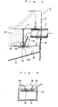
- Fig. 1 is a cross-sectional view showing an example of the wet dust collecting apparatus according to the present invention;
- Fig. 2 is a left side view of said wet dust-collecting apparatus;
- Fig. 3 is an enlarged view for illustrating the construction of a communication portion between the suction passage and the mist room; and
- Fig. 4 is an enlarged view for explaining the mist generating principle by a mist generator in the wet dust collecting apparatus.
- Now, the present invention will be described in detail based on an example illustrated in the accompanying drawings.
- As shown in Figs. 1 and 2, the wet
dust collecting apparatus 1 for collecting fume dust generated when machining with a laser and plasma machine comprises ahousing 2, asuction passage 3 formed in thehousing 2 for sucking high temperature laser and plasma dust, awater tub 4 arranged downstream of thesuction passage 3, amist room 5 formed in upper portion of thewater tub 4, a mist separatingfilter 6 of collision and inertia type arranged above themist room 5, a fan for sucking the laser and plasma dust from thesuction passage 3 through themist room 5 to themist filter 6 of inertial mist separator type, and combtoothed mist generator 8 arranged at a communication portion between thesuction passage 3 andmist room 5. - The
housing 2 is provided on its bottom face withcasters 9 for facilitating movement thereof. Thesuction passage 3 is formed from heat resisting material and anextendable duct 10 is connected at upstream end of thesuction passage 3 so as to communicate therewith. The front end of theduct 10 is connected to a fume dust generating portion of the laser beam and plasma arc cutting machine (not shown). - Fixed by means of a fixture on the lower end of a
partition plate 11 which confines the downstream of thesuction passage 3 is themist generator 8, while arestriction plate 12 is arranged slanted at a position in thesuction passage 3 opposite to thepartition plate 11. Of course, between thelower end 12a of therestriction plate 12 and the lower end of themist generator 8 is formed a slight gap. Therestriction plate 12 may be of course formed integrally with themist generator 8. - The
mist generator 8 is arranged such that the comb-toothed section 13 which comprises continuous convexes and concaves is partly immersed in the water in thewater tub 4 as shown in Figs. 3 and 4, and thus there is formed a number of narrow dust-containingair lanes 14 arranged side by side by the comb-toothed section 13 and the water surface W. - Accordingly, the fume dust sucked into the
suction passage 3 flows through the gap between thepartition plate 11 and therestriction plate 12 except the dust that directly drops into the water of thewater tub 4. Since the gap between thepartition plate 11 and therestriction plate 12 is gradually narrowed as it approaches the water surface W, the dust-containing air flowing in the gap is gradually speeded up and then flows into themist room 5 passing through the dust-containingair lanes 14 of themist generator 8. At this time, the dust-containing air passing through the dust-containingair lanes 14 forces the water surface W to vibrate at high speed so as to generate mist which floats in themist room 5 and thus there is formed a perfect mist atmosphere. - Of course, by adjusting the height of the water surface W, the amount of generated mist can be appropriately adjusted, because the degree of opening of the dust containing
air lanes 14 is increased or decreased. - As for the
water tub 4, it is arranged under thehousing 2, and in the water is immersed a lower end portion 2a of the side wall of thehousing 2 so as to form themist room 5 together with both the water surface W and thepartition plate 11. - At the bottom of the
water tub 4 is formed aslope 16 and the sludgy dust precipitated and deposited thereon flows into thepocket 4a to be gathered therein. - Each filter element of the
mist separating filter 6 is formed of an aluminium alloy, stainless steel or the like which has excellent heat resistance, water resistance and corrosion resistance, and, though unillustrated in the drawings, a plurality of L-typed plates thereof are precisely arranged and fixed to a frame. - The
fan 7 can be an air suction type employed in conventional dust collecting apparatus and therefore detailed explanation thereof will be omitted. - Since the wet
dust collecting apparatus 1 according to this embodiment is constructed as above, the hot laser and plasma dust sucked into thesuction passage 3 of thehousing 1 by the action of thefan 7 flows through a gradually narrowed gap between thepartition plate 11 and therestriction plate 12 and, after its flow velocity has been gradually increased as it approaches the water surface W, further passes through further restricted dust-containingair lanes 14 in themist generator 8 with high speed. The dust-containing air thus speeded up in the dust-containingair lanes 14 forces the water surface W to vibrate with high speed so as to generate mist on the water surface W with waterdrops of the water surface W finely grained, and the mist thus generated is sent into themist room 5 and floats therein. - Since the mist thus generated is floating in the
mist room 5, the laser and plasma dust contained in the air is rebounded on the water surface and introduced into themist room 5, and then sucked into themist separating filter 6 by thefan 7 after adhering to the mist within themist room 5. Since the laser and plasma dust is very fine, the dust collection can be effectively carried out by making it adhere to the mist. Of course, the laser and plasma dust which is dropped in the water without rebounding on the water surface W is left precipitated on the bottom of thewater tub 4. - With the
mist separating filter 6, the laser and plasma dust adhered to the mist is effectively collected by the principle of collision and inertia and flows down together with the moisture content to be removed. The collected laser and plasma dust may flow down into thewater tub 4 together with the moisture content. - Clean air after completion of the dust collection work by the
mist separating filter 6 is then exhausted outside thehousing 2 by the action of thefan 7 . - A
slope 16 is provided on the bottom portion of thewater tub 4 and the sludgy dust precipitated and deposited flows down into apocket portion 4a and condenses to some degree of hardness so as to be easily removed. Alternatively, the sludgy dust may be automatically removed out of the apparatus by means of a screw conveyer or the like. - While the present invention is explained in the above embodiment by means of an example applied to the wet dust collecting apparatus for collecting laser and plasma dust, it is not limited to such dust and can be applied also to other wet dust collecting apparatus for collecting cold dust or other fine dust generated in large quantities with a shotblast, sanding machine or the like.
- Further, in the present invention, it may be arranged that the water level adjustment of the total area of the dust containing
air lanes 14 of themist generator 8 is automatically controlled by utilizing pressure loss which changes in accordance with the amount of sucked air.
Claims (8)
- Wet dust collecting apparatus (1) comprising:a housing (2);a suction passage (3) leading into the housing for sucking in dust;a water reservoir (4) disposed in the housing (2);a mist chamber (5) which is above the water reservoir (4) and downstream of the suction passage (3);a dust filter (6) which is downstream of the mist chamber (5);a fan (7) for sucking dust from the suction passage (3) through the mist chamber (5) to the filter (6); anda comb-toothed mist generator (8) disposed at a position of communication between the suction passage (3) and the mist chamber (5);the arrangement being such that dust-containing air sucked into the suction passage (3) is directed against the mist generator (8) so as to vibrate the surface of water in the water reservoir (4) at high speed to generate mist in the mist chamber (5) which carries the dust to the dust filter (6).
- Wet dust collecting apparatus according to claim 1, wherein the teeth of the mist generator (8) have their lower ends immersed in the water of the water reservoir (4).
- Wet dust collecting apparatus according to claim 1 or 2, further comprising a partition plate (11) which separates the suction passage (3) from the mist chamber (5).
- Wet dust collecting apparatus according to claim 3, wherein the comb-toothed mist generator (8) extends downwards from the lower end of the partition plate (11).
- Wet dust collecting apparatus according to any one of claims 1 to 4, wherein the suction passage (3) includes a final portion (11, 12) which tapers as it approaches the mist generator (8) so as to increase the speed of the air flowing therethrough towards the mist generator (8).
- Wet dust collecting apparatus according to claim 5, wherein the final portion (11, 12) of the suction passage (3) defines a flow direction which points downwards.
- Wet dust collecting apparatus according to claim 6, wherein the final portion (11, 12) of the suction passage (3) is arranged to direct the dust-containing air through the mist generator (8) and also against a part of the water surface of the water reservoir (4) immediately upstream of the mist generator (8).
- Wet dust collecting apparatus according to claim 5, 6 or 7, wherein the final portion (11, 12) of the suction passage (3) is arranged to receive an upper part of the air flow which enters the suction passage and to deflect a lower part of that air flow down towards the water surface of the water reservoir (4).
Applications Claiming Priority (3)
| Application Number | Priority Date | Filing Date | Title |
|---|---|---|---|
| JP188696/95 | 1995-06-30 | ||
| JP18869695A JP3695665B2 (en) | 1995-06-30 | 1995-06-30 | Wet dust collector |
| JP18869695 | 1995-06-30 |
Publications (3)
| Publication Number | Publication Date |
|---|---|
| EP0750931A2 true EP0750931A2 (en) | 1997-01-02 |
| EP0750931A3 EP0750931A3 (en) | 1997-04-09 |
| EP0750931B1 EP0750931B1 (en) | 2001-09-12 |
Family
ID=16228225
Family Applications (1)
| Application Number | Title | Priority Date | Filing Date |
|---|---|---|---|
| EP96304791A Expired - Lifetime EP0750931B1 (en) | 1995-06-30 | 1996-06-28 | Wet dust collecting apparatus |
Country Status (5)
| Country | Link |
|---|---|
| US (1) | US5762663A (en) |
| EP (1) | EP0750931B1 (en) |
| JP (1) | JP3695665B2 (en) |
| DE (1) | DE69615096T2 (en) |
| ES (1) | ES2161979T3 (en) |
Cited By (3)
| Publication number | Priority date | Publication date | Assignee | Title |
|---|---|---|---|---|
| WO2009109763A1 (en) * | 2008-03-07 | 2009-09-11 | Reckitt Benckiser (Uk) Limited | An air cleaner |
| CN104971575A (en) * | 2014-04-09 | 2015-10-14 | 苏州鼎德电环保科技有限公司 | Gas-liquid-solid separator, gas-liquid separator and plasma desulfurization and denitrification device comprising gas-liquid-solid separator and gas-liquid separator |
| EP3981496A1 (en) * | 2020-10-07 | 2022-04-13 | Absaugwerk GmbH | Wet separator |
Families Citing this family (13)
| Publication number | Priority date | Publication date | Assignee | Title |
|---|---|---|---|---|
| US6398197B1 (en) * | 1999-05-10 | 2002-06-04 | Fisher & Paykel Limited | Water chamber |
| KR100389003B1 (en) * | 2000-10-09 | 2003-06-25 | 삼성전자주식회사 | Disk balancing apparatus and a balancing method |
| KR20020097444A (en) * | 2001-06-21 | 2002-12-31 | 이성규 | Wet type dust collector |
| JP2003038926A (en) * | 2001-07-31 | 2003-02-12 | Daiei Seisakusho:Kk | Dust collector |
| RU2279304C1 (en) * | 2005-03-21 | 2006-07-10 | Олег Савельевич Кочетов | Ventilation wet dust-catcher |
| JP5706235B2 (en) * | 2011-05-26 | 2015-04-22 | 株式会社ディスコ | Laser processing equipment |
| US8580021B1 (en) | 2011-06-28 | 2013-11-12 | Florencio A. McPherson | Portable air scrubber device |
| CN102758463A (en) * | 2012-07-24 | 2012-10-31 | 太原重工股份有限公司 | Dedusting device of excavator |
| US20140053722A1 (en) * | 2012-08-21 | 2014-02-27 | Paul Cacciotti | Machine tool mounted mist collector with automatic control |
| CN103816747B (en) * | 2014-02-26 | 2015-12-09 | 广州市番禺奥迪威电子有限公司 | The device of a kind of air purification method and this air purification method of enforcement |
| CN105169851B (en) * | 2015-08-24 | 2017-03-22 | 中国矿业大学 | Device and method for modulating liquid phase resonance water attack of auto-excitation type deduster |
| CN111939704B (en) * | 2020-08-19 | 2022-04-15 | 东营市美城环境清洁有限责任公司 | Dust collector for building engineering |
| US12599860B2 (en) * | 2021-11-16 | 2026-04-14 | Edwards Vacuum Llc | Liquid filter apparatus with thermal shield |
Family Cites Families (12)
| Publication number | Priority date | Publication date | Assignee | Title |
|---|---|---|---|---|
| US1062446A (en) * | 1912-12-13 | 1913-05-20 | Alfred Ernst | Gas-cleaner. |
| US2048145A (en) * | 1932-01-20 | 1936-07-21 | Donald A Sillers | Contact apparatus and method for contacting liquid and gas |
| US2015174A (en) * | 1934-02-09 | 1935-09-24 | Herman B Anglemyer | Air cleaner |
| US2491645A (en) * | 1944-11-23 | 1949-12-20 | Vilbiss Co | Apparatus for washing air |
| GB1162143A (en) * | 1966-08-25 | 1969-08-20 | Nikex Nehezipari Kulkere | Process and apparatus for Intimately Contacting a Gas and a Liquid |
| US3581467A (en) * | 1969-12-04 | 1971-06-01 | Frank M Donnelly | Method and apparatus for vortical liquid-gas movement |
| US3812658A (en) * | 1973-05-14 | 1974-05-28 | Peabody Engineering Corp | Gas cleaning apparatus |
| IT1091078B (en) * | 1977-10-25 | 1985-06-26 | Whitehead Moto Fides Stabil | OIL BATH AIR FILTER |
| US5078759A (en) * | 1990-10-15 | 1992-01-07 | Kira Alan K | Apparatus and method for precipitating particles from a gaseous stream |
| US5292353A (en) * | 1991-07-03 | 1994-03-08 | The Delfield Company | Air scrubber |
| DE4229895C2 (en) * | 1992-09-11 | 1997-01-30 | Steinmueller Gmbh L & C | Device for cooling a hot gas, in particular a hot useful gas generated in a combustion or gasification chamber by burning carbon-containing fuel |
| DE4331685A1 (en) * | 1993-09-17 | 1995-03-23 | Linde Ag | Procedure for operating a diving and diving |
-
1995
- 1995-06-30 JP JP18869695A patent/JP3695665B2/en not_active Expired - Fee Related
-
1996
- 1996-04-23 US US08/636,239 patent/US5762663A/en not_active Expired - Fee Related
- 1996-06-28 ES ES96304791T patent/ES2161979T3/en not_active Expired - Lifetime
- 1996-06-28 DE DE69615096T patent/DE69615096T2/en not_active Expired - Fee Related
- 1996-06-28 EP EP96304791A patent/EP0750931B1/en not_active Expired - Lifetime
Cited By (6)
| Publication number | Priority date | Publication date | Assignee | Title |
|---|---|---|---|---|
| WO2009109763A1 (en) * | 2008-03-07 | 2009-09-11 | Reckitt Benckiser (Uk) Limited | An air cleaner |
| CN102015064A (en) * | 2008-03-07 | 2011-04-13 | 雷克特和科尔曼(海外)有限公司 | An air cleaner |
| US8728208B2 (en) | 2008-03-07 | 2014-05-20 | Reckitt & Colman (Overseas) Limited | Air cleaner |
| CN104971575A (en) * | 2014-04-09 | 2015-10-14 | 苏州鼎德电环保科技有限公司 | Gas-liquid-solid separator, gas-liquid separator and plasma desulfurization and denitrification device comprising gas-liquid-solid separator and gas-liquid separator |
| CN104971575B (en) * | 2014-04-09 | 2019-02-01 | 苏州鼎德电环保科技有限公司 | Gas-liquid-solid separator, gas-liquid separator and its plasma-based sulphur removal denitration device |
| EP3981496A1 (en) * | 2020-10-07 | 2022-04-13 | Absaugwerk GmbH | Wet separator |
Also Published As
| Publication number | Publication date |
|---|---|
| DE69615096D1 (en) | 2001-10-18 |
| ES2161979T3 (en) | 2001-12-16 |
| EP0750931A3 (en) | 1997-04-09 |
| US5762663A (en) | 1998-06-09 |
| DE69615096T2 (en) | 2002-06-20 |
| JP3695665B2 (en) | 2005-09-14 |
| JPH0910536A (en) | 1997-01-14 |
| EP0750931B1 (en) | 2001-09-12 |
Similar Documents
| Publication | Publication Date | Title |
|---|---|---|
| EP0750931B1 (en) | Wet dust collecting apparatus | |
| AU647733B2 (en) | Cyclonic separator for removing and recovering airborne particles | |
| GB1595975A (en) | Apparatus for separating particles from gases | |
| JPH0739645B2 (en) | Cleaning device | |
| JPS6138646Y2 (en) | ||
| JPH10192628A (en) | Dust collector | |
| JP2001355824A (en) | Waste incinerator with dust and ash removal device | |
| CA2358580C (en) | Droplet separator | |
| JP4780486B2 (en) | Dust collector | |
| GB2198058A (en) | Filter | |
| JP3779344B2 (en) | Dust collector consisting of perforated screen | |
| SE426915B (en) | FILTERING DEVICE WITH SLAUGHTER MECHANISM THAT ALLOWS CLEANING OF A SUBSTANTABLE FILTERING MEDIUM FROM AIR-SEPARATED DUST | |
| NO762817L (en) | ||
| JPH0655022A (en) | Gravity settlement type dust collector | |
| KR950010938A (en) | Oil mist collector | |
| KR20020016246A (en) | Adhesion plate structure for impingement eliminator | |
| GB2006046A (en) | Method and apparatus for separating particulate pollutants from a stream of air or other gas | |
| JPH052722U (en) | Wet dust collector | |
| JPH08141342A (en) | Dust collection member with turning panel | |
| TWI758442B (en) | Compact dedusting apparatus with remote discharge | |
| JPH10170045A (en) | Range hood | |
| SU827128A1 (en) | Dust trap | |
| JPH043617Y2 (en) | ||
| JPH08266832A (en) | Dust collector | |
| RU2159144C2 (en) | Jet-type inertial dust collector |
Legal Events
| Date | Code | Title | Description |
|---|---|---|---|
| PUAI | Public reference made under article 153(3) epc to a published international application that has entered the european phase |
Free format text: ORIGINAL CODE: 0009012 |
|
| AK | Designated contracting states |
Kind code of ref document: A2 Designated state(s): CH DE ES FI FR GB IT LI SE |
|
| PUAL | Search report despatched |
Free format text: ORIGINAL CODE: 0009013 |
|
| AK | Designated contracting states |
Kind code of ref document: A3 Designated state(s): CH DE ES FI FR GB IT LI SE |
|
| 17P | Request for examination filed |
Effective date: 19970915 |
|
| 17Q | First examination report despatched |
Effective date: 19990414 |
|
| GRAG | Despatch of communication of intention to grant |
Free format text: ORIGINAL CODE: EPIDOS AGRA |
|
| GRAG | Despatch of communication of intention to grant |
Free format text: ORIGINAL CODE: EPIDOS AGRA |
|
| GRAH | Despatch of communication of intention to grant a patent |
Free format text: ORIGINAL CODE: EPIDOS IGRA |
|
| GRAH | Despatch of communication of intention to grant a patent |
Free format text: ORIGINAL CODE: EPIDOS IGRA |
|
| GRAA | (expected) grant |
Free format text: ORIGINAL CODE: 0009210 |
|
| AK | Designated contracting states |
Kind code of ref document: B1 Designated state(s): CH DE ES FI FR GB IT LI SE |
|
| REG | Reference to a national code |
Ref country code: CH Ref legal event code: NV Representative=s name: MICHELI & CIE INGENIEURS-CONSEILS Ref country code: CH Ref legal event code: EP |
|
| REF | Corresponds to: |
Ref document number: 69615096 Country of ref document: DE Date of ref document: 20011018 |
|
| ET | Fr: translation filed | ||
| REG | Reference to a national code |
Ref country code: ES Ref legal event code: FG2A Ref document number: 2161979 Country of ref document: ES Kind code of ref document: T3 |
|
| REG | Reference to a national code |
Ref country code: GB Ref legal event code: IF02 |
|
| PLBE | No opposition filed within time limit |
Free format text: ORIGINAL CODE: 0009261 |
|
| STAA | Information on the status of an ep patent application or granted ep patent |
Free format text: STATUS: NO OPPOSITION FILED WITHIN TIME LIMIT |
|
| 26N | No opposition filed | ||
| PGFP | Annual fee paid to national office [announced via postgrant information from national office to epo] |
Ref country code: SE Payment date: 20040630 Year of fee payment: 9 Ref country code: FI Payment date: 20040630 Year of fee payment: 9 |
|
| PGFP | Annual fee paid to national office [announced via postgrant information from national office to epo] |
Ref country code: FR Payment date: 20040721 Year of fee payment: 9 Ref country code: DE Payment date: 20040721 Year of fee payment: 9 |
|
| PGFP | Annual fee paid to national office [announced via postgrant information from national office to epo] |
Ref country code: CH Payment date: 20040723 Year of fee payment: 9 |
|
| PGFP | Annual fee paid to national office [announced via postgrant information from national office to epo] |
Ref country code: GB Payment date: 20040726 Year of fee payment: 9 |
|
| PGFP | Annual fee paid to national office [announced via postgrant information from national office to epo] |
Ref country code: ES Payment date: 20040728 Year of fee payment: 9 |
|
| PG25 | Lapsed in a contracting state [announced via postgrant information from national office to epo] |
Ref country code: FI Free format text: LAPSE BECAUSE OF NON-PAYMENT OF DUE FEES Effective date: 20050614 |
|
| PG25 | Lapsed in a contracting state [announced via postgrant information from national office to epo] |
Ref country code: IT Free format text: LAPSE BECAUSE OF NON-PAYMENT OF DUE FEES Effective date: 20050628 Ref country code: GB Free format text: LAPSE BECAUSE OF NON-PAYMENT OF DUE FEES Effective date: 20050628 |
|
| PG25 | Lapsed in a contracting state [announced via postgrant information from national office to epo] |
Ref country code: SE Free format text: LAPSE BECAUSE OF NON-PAYMENT OF DUE FEES Effective date: 20050629 Ref country code: ES Free format text: LAPSE BECAUSE OF NON-PAYMENT OF DUE FEES Effective date: 20050629 |
|
| PG25 | Lapsed in a contracting state [announced via postgrant information from national office to epo] |
Ref country code: LI Free format text: LAPSE BECAUSE OF NON-PAYMENT OF DUE FEES Effective date: 20050630 Ref country code: CH Free format text: LAPSE BECAUSE OF NON-PAYMENT OF DUE FEES Effective date: 20050630 |
|
| PG25 | Lapsed in a contracting state [announced via postgrant information from national office to epo] |
Ref country code: DE Free format text: LAPSE BECAUSE OF NON-PAYMENT OF DUE FEES Effective date: 20060103 |
|
| REG | Reference to a national code |
Ref country code: CH Ref legal event code: PL |
|
| EUG | Se: european patent has lapsed | ||
| PG25 | Lapsed in a contracting state [announced via postgrant information from national office to epo] |
Ref country code: FR Free format text: LAPSE BECAUSE OF NON-PAYMENT OF DUE FEES Effective date: 20060228 |
|
| GBPC | Gb: european patent ceased through non-payment of renewal fee |
Effective date: 20050628 |
|
| REG | Reference to a national code |
Ref country code: FR Ref legal event code: ST Effective date: 20060228 |
|
| REG | Reference to a national code |
Ref country code: ES Ref legal event code: FD2A Effective date: 20050629 |