EP0753634A1 - Tent structure - Google Patents
Tent structure Download PDFInfo
- Publication number
- EP0753634A1 EP0753634A1 EP95304919A EP95304919A EP0753634A1 EP 0753634 A1 EP0753634 A1 EP 0753634A1 EP 95304919 A EP95304919 A EP 95304919A EP 95304919 A EP95304919 A EP 95304919A EP 0753634 A1 EP0753634 A1 EP 0753634A1
- Authority
- EP
- European Patent Office
- Prior art keywords
- tent
- supporting pole
- pole
- poles
- main
- Prior art date
- Legal status (The legal status is an assumption and is not a legal conclusion. Google has not performed a legal analysis and makes no representation as to the accuracy of the status listed.)
- Withdrawn
Links
- 230000008878 coupling Effects 0.000 claims description 2
- 238000010168 coupling process Methods 0.000 claims description 2
- 238000005859 coupling reaction Methods 0.000 claims description 2
- 238000005452 bending Methods 0.000 description 8
- 230000003014 reinforcing effect Effects 0.000 description 3
- 238000004519 manufacturing process Methods 0.000 description 2
- 238000000034 method Methods 0.000 description 2
Images


Classifications
-
- E—FIXED CONSTRUCTIONS
- E04—BUILDING
- E04H—BUILDINGS OR LIKE STRUCTURES FOR PARTICULAR PURPOSES; SWIMMING OR SPLASH BATHS OR POOLS; MASTS; FENCING; TENTS OR CANOPIES, IN GENERAL
- E04H15/00—Tents or canopies, in general
- E04H15/32—Parts, components, construction details, accessories, interior equipment, specially adapted for tents, e.g. guy-line equipment, skirts, thresholds
- E04H15/34—Supporting means, e.g. frames
Definitions
- the invention is related to providing a tent structure, and in particular, to providing a tent structure for enabling a tent to be supported by a truss configuration support structure.
- a conventional tent includes only a structure supported with the tension force of its own skin and the bending strength of supporting poles being mutually connected. But, the tent can not only maintain its structural shape without the skin, but also is easily put out of shape by external force.
- the main object of the invention is to provide a new tent structure for affording a predetermined strength to a tent without reinforcing the tent skins.
- Another object of the invention is to provide a new tent structure for coupling an auxiliary supporting pole to a main supporting pole in a truss configuration, thereby affording a structural strength having the flexibility in height with respect to a tent.
- Still another object of the invention is to provide a new tent structure for adapting the truss configuration to the lower portions of the main pole, thereby reinforcing the strength of the tent's lower portion.
- a tent structure comprises a truss configuration formed on the lower portion of the main supporting pole in order to reinforce the lower portion of a tent. Furthermore, a tent structure comprises an auxiliary supporting pole coupled in a truss configuration to a main supporting pole in order to afford a structural strength having the flexibility in height with respect to a tent.
- a tent 10 is a dome type tent of X-character, at the apex point A of which main supporting poles 1 and 2 are crossed and attached to each other.
- the tent 10 includes auxiliary supporting poles 4 and 5 attached to the position B of the main pole at the predetermined height h by means of a connector(as described below in detail).
- the auxiliary supporting poles 4 and 5 are constructed in a truss configuration to make the shapes of B-C-B' and B-C-B'' centering on the position B. The configuration enables the main supporting pole to be supported only by the axial load to increase the structural bending strength.
- E is an elasticity coefficient
- I is a moment of inertia
- P is a center load
- l is a length of a supporting pole.
- the proportion between the bending stress applied to the full length of the poles and the bending stress applied to the distance of the position B to a position C or the distance of the position D to the position E is 8 : 1.
- the main supporting pole 10 supported in a truss configuration by auxiliary supporting poles 4 and 5 is superior to a pole not constructed as a truss configuration by eight times in respect to its strength.
- the main supporting poles 1 and 2 require a connector to form the truss configuration with auxiliary supporting poles 4 and 5.
- a connector 20 comprises a supporter 21 inserted into the predetermined position of a main supporting pole 1 and a fixture 22 attached to the supporter 21, on both sides of which cap portions 26 and 27 are mounted with each of the auxiliary supporting poles 4 and 5 being supported received.
- the supporter 21 includes a body in the form of a cylinder and a positioning fixture 23 determining the fixing position to be inserted into the main supporting pole, in which the positioning fixture 23 is inserted into the body to contact with the main supporting pole 1 or to be supported in the hole of the main supporting pole 1, and also the fixture 21 includes a projector 24 integrally extended therefrom in a position faced against the positioning fixture 23.
- a supporting plate 25 having a hole is inserted onto the projector 24 to couple the fixture 22 to the supporter 21 along with auxiliary supporting poles 4 and 5, so that the pole supporting pole 1 forms a truss configuration by means of auxiliary supporting poles 4 and 5.
- Fig. 3 shows another embodiment of a connecter 30 according to the invention.
- the connecter 30 includes a circular plate in a truncated cone configuration.
- the connecter 30 has a main hole 31 formed on one side thereof and auxiliary holes 32 and 33 formed in a triangle shape to the main hole 31, into which the auxiliary supporting poles 4 and 5 are inserted.
- the main hole 31 is perforated in the slant of 15 o to 30 o to the vertical line in order to install the main supporting pole 1 at an angle of 60 o to 75 o .
- the auxiliary holes 32 and 33 are perforated in the slant of around 30 o to the vertical line.
- Fig. 4 shows another embodiment of the connecter according to the invention.
- the connector 40 is curved in a predetermined length as a bar configuration of a tube type.
- the connecter 40 includes a main hole 41 enabling the main supporting pole 1 to be inserted into the center portion thereof and extending portions 42 and 43 having receiving portions 42 and 45 to be fitted therein, which is extended leftward and rightward by a determined distance from the main hole 41 and then the extending portions are curved downward. Therefore, the connecter 40 establishes the truss configuration by inserting auxiliary supporting poles into extending portions 42 and 43, respectively, with the main supporting pole 1 being inserted therein.
- the truss configuration enables auxiliary supporting poles to reinforce the lower portion of a main supporting pole as well as to support a tent body.
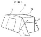
- a tent structure 50 comprises at least main supporting poles 51, 52 and at least two auxiliary supporting poles 53, 54, which are staggeringly crossed against one another to form a truss configuration.
- the main supporting poles 51 and 52 determining the height of a tent are fixed to the ground, so that both of their ends are sloped at a predetermined angle.
- the auxiliary supporting pole 53 passes at a predetermined height over one side of the main supporting poles 51 and 52, so that they are fixed at their intersecting point (a) to one another by means of a connecter or the tent skin. Therefore, the main supporting pole 51 and the auxiliary supporting pole 53 have a point b, contacting the main supporting pole 51 with the ground, and a point c, on the other hand, contacting the auxiliary supporting pole 53 with the ground, to form the truss configuration (a, b, c).
- the tent structure 50 is constructed as the truss configuration to have the axial load at the point a, thereby reducing the bending stress based on the center load of the supporting poles and remarkably improving the strength of the tent structure.
Landscapes
- Engineering & Computer Science (AREA)
- Architecture (AREA)
- Civil Engineering (AREA)
- Structural Engineering (AREA)
- Tents Or Canopies (AREA)
Abstract
A tent structure comprises a truss configuration formed on the lower portion of a main supporting pole (1,2) in order to reinforce the lower portion of a tent (10). Furthermore, a tent structure comprises an auxiliary supporting pole (4,5) coupled in a truss configuration to a main supporting pole (1,2) in order to afford a structural strength having the flexibility with respect to the height of a tent (10).
Description
- The invention is related to providing a tent structure, and in particular, to providing a tent structure for enabling a tent to be supported by a truss configuration support structure.
- A conventional tent includes only a structure supported with the tension force of its own skin and the bending strength of supporting poles being mutually connected. But, the tent can not only maintain its structural shape without the skin, but also is easily put out of shape by external force.
- Also, contemporary tents have become much larger following the increased bending strength of supporting poles. Generally, a method for preventing the stress of a tent by external forces or increasing the strength of the tent structure was to enlarge the diameter of supporting poles as well as to increase the number of supporting poles. This method is reversed to the tendency for manufacturing a lighter tent and has disadvantages in that the cost of materials for poles is expensive, thereby increasing the cost for manufacturing the tent. Therefore, the tent should be designed to develop a new structure.
- Herein, it is very advantageous to provide a predetermined strength of a tent even using conventional poles without reinforcing its own skin in order to increase the strength of the tent.
- Accordingly, the main object of the invention is to provide a new tent structure for affording a predetermined strength to a tent without reinforcing the tent skins.
- Another object of the invention is to provide a new tent structure for coupling an auxiliary supporting pole to a main supporting pole in a truss configuration, thereby affording a structural strength having the flexibility in height with respect to a tent.
- Still another object of the invention is to provide a new tent structure for adapting the truss configuration to the lower portions of the main pole, thereby reinforcing the strength of the tent's lower portion.
- According to the invention, a tent structure comprises a truss configuration formed on the lower portion of the main supporting pole in order to reinforce the lower portion of a tent. Furthermore, a tent structure comprises an auxiliary supporting pole coupled in a truss configuration to a main supporting pole in order to afford a structural strength having the flexibility in height with respect to a tent.
- The invention will be described below in detail with reference to the accompanying drawings, in which;
- Fig. 1 is a view illustrating a tent structure of one embodiment adapting the truss configuration to the lower portion of a supporting pole used in a dome type tent according to the invention;
- Fig. 2 is a perspective view illustrating the connector of a first embodiment used in forming the truss configuration at the lower portion of a supporting pole according to the invention;
- Fig. 3 is a perspective view illustrating the connector of a second embodiment according to the invention;
- Fig. 4 is a perspective view illustrating the connector of a second embodiment according to the invention; and
- Fig. 5 is a view illustrating a tent structure of another embodiment using a truss configuration as a main supporting pole and an auxiliary pole according to the invention.
- Referring to Fig. 1, a
tent 10 is a dome type tent of X-character, at the apex point A of which main supportingpoles 1 and 2 are crossed and attached to each other. Thetent 10 includes auxiliary supportingpoles poles 
- Wherein, E is an elasticity coefficient, I is a moment of inertia, P is a center load and l is a length of a supporting pole.
- Based on the formula, the greater the full length of a supporting pole becomes, the larger the bending stress δ increases in a geometrical series. Thus, if the height of the tent becomes higher, it should require a larger diameter and thickness of the poles.
- For example, assuming that the full length of the main supporting
pole 1 is 4m, and each of the distances from a position B to a position C and from a position D to a position E is 1m, the proportion between the bending stress applied to the full length of the poles and the bending stress applied to the distance of the position B to a position C or the distance of the position D to the position E is 8 : 1. Thus, it is noted that the main supportingpole 10 supported in a truss configuration by auxiliary supportingpoles poles 1 and 2 require a connector to form the truss configuration with auxiliary supportingpoles - As shown in Fig. 2, a
connector 20 comprises asupporter 21 inserted into the predetermined position of a main supportingpole 1 and afixture 22 attached to thesupporter 21, on both sides of whichcap portions poles supporter 21 includes a body in the form of a cylinder and apositioning fixture 23 determining the fixing position to be inserted into the main supporting pole, in which thepositioning fixture 23 is inserted into the body to contact with the main supportingpole 1 or to be supported in the hole of the main supportingpole 1, and also thefixture 21 includes aprojector 24 integrally extended therefrom in a position faced against thepositioning fixture 23. Therefore, a supportingplate 25 having a hole is inserted onto theprojector 24 to couple thefixture 22 to thesupporter 21 along with auxiliary supportingpoles pole supporting pole 1 forms a truss configuration by means of auxiliary supportingpoles - Fig. 3 shows another embodiment of a
connecter 30 according to the invention. Theconnecter 30 includes a circular plate in a truncated cone configuration. Theconnecter 30 has amain hole 31 formed on one side thereof andauxiliary holes main hole 31, into which the auxiliary supportingpoles main hole 31 is perforated in the slant of 15o to 30o to the vertical line in order to install the main supportingpole 1 at an angle of 60o to 75o. Theauxiliary holes - Fig. 4 shows another embodiment of the connecter according to the invention. The
connector 40 is curved in a predetermined length as a bar configuration of a tube type. In other words, theconnecter 40 includes amain hole 41 enabling the main supportingpole 1 to be inserted into the center portion thereof and extendingportions 42 and 43 having receivingportions main hole 41 and then the extending portions are curved downward. Therefore, theconnecter 40 establishes the truss configuration by inserting auxiliary supporting poles into extendingportions 42 and 43, respectively, with the main supportingpole 1 being inserted therein. - On the other hand, according to the invention, the truss configuration enables auxiliary supporting poles to reinforce the lower portion of a main supporting pole as well as to support a tent body.
- As shown in Fig. 5, a
tent structure 50 comprises at least main supportingpoles poles - Namely, the main supporting
poles pole 53 passes at a predetermined height over one side of the main supportingpoles pole 51 and the auxiliary supportingpole 53 have a point b, contacting the main supportingpole 51 with the ground, and a point c, on the other hand, contacting the auxiliary supportingpole 53 with the ground, to form the truss configuration (a, b, c). Similarly, the main supportingpoles pole 53 are coupled in a truss configuration to one another. Accordingly, thetent structure 50 is constructed as the truss configuration to have the axial load at the point a, thereby reducing the bending stress based on the center load of the supporting poles and remarkably improving the strength of the tent structure.
Claims (3)
- A tent structure comprising:
main supporting poles and auxiliary supporting poles, in which at least one auxiliary supporting pole is coupled in a truss configuration to the main supporting pole. - The tent structure as claimed in Claim 1, further comprising:
a connecter coupling at least one auxiliary supporting pole to the main supporting pole. - A tent structure comprising:
an auxiliary supporting pole is crossed over at least one main supporting pole and coupled to one another to form a truss configuration.
Priority Applications (1)
| Application Number | Priority Date | Filing Date | Title |
|---|---|---|---|
| EP95304919A EP0753634A1 (en) | 1995-07-13 | 1995-07-13 | Tent structure |
Applications Claiming Priority (1)
| Application Number | Priority Date | Filing Date | Title |
|---|---|---|---|
| EP95304919A EP0753634A1 (en) | 1995-07-13 | 1995-07-13 | Tent structure |
Publications (1)
| Publication Number | Publication Date |
|---|---|
| EP0753634A1 true EP0753634A1 (en) | 1997-01-15 |
Family
ID=8221259
Family Applications (1)
| Application Number | Title | Priority Date | Filing Date |
|---|---|---|---|
| EP95304919A Withdrawn EP0753634A1 (en) | 1995-07-13 | 1995-07-13 | Tent structure |
Country Status (1)
| Country | Link |
|---|---|
| EP (1) | EP0753634A1 (en) |
Cited By (7)
| Publication number | Priority date | Publication date | Assignee | Title |
|---|---|---|---|---|
| KR20030013784A (en) * | 2001-08-09 | 2003-02-15 | 라제건 | Wind Resistance Tent |
| GB2419901A (en) * | 2004-11-04 | 2006-05-10 | Baejin Corp | Reinforcing leg support for use with tent pole |
| DE102013019276A1 (en) | 2013-05-14 | 2014-11-20 | Vaude Gmbh & Co. Kg | Trekking tent |
| DE102016118739A1 (en) | 2016-10-04 | 2018-04-05 | Vaude Gmbh & Co. Kg | Tent with structure and tent roof |
| DE202018105847U1 (en) | 2018-10-12 | 2018-11-09 | Gerald Hecht | Pavilion or tent |
| EP3636859A1 (en) | 2018-10-12 | 2020-04-15 | Gerald Hecht | Pavilion or tent |
| US11572704B2 (en) | 2018-10-12 | 2023-02-07 | Gerald Hecht | Gazebo or tent |
Citations (3)
| Publication number | Priority date | Publication date | Assignee | Title |
|---|---|---|---|---|
| US2856941A (en) * | 1957-03-19 | 1958-10-21 | Earl C O'neal | Portable garage |
| US3122152A (en) * | 1960-12-30 | 1964-02-25 | Messer Maurice | Transportable and convertible shelter |
| US3424178A (en) * | 1965-11-04 | 1969-01-28 | Yoshimi Yazaki | Small size constructions which are readily fabricated or dismantled |
-
1995
- 1995-07-13 EP EP95304919A patent/EP0753634A1/en not_active Withdrawn
Patent Citations (3)
| Publication number | Priority date | Publication date | Assignee | Title |
|---|---|---|---|---|
| US2856941A (en) * | 1957-03-19 | 1958-10-21 | Earl C O'neal | Portable garage |
| US3122152A (en) * | 1960-12-30 | 1964-02-25 | Messer Maurice | Transportable and convertible shelter |
| US3424178A (en) * | 1965-11-04 | 1969-01-28 | Yoshimi Yazaki | Small size constructions which are readily fabricated or dismantled |
Cited By (7)
| Publication number | Priority date | Publication date | Assignee | Title |
|---|---|---|---|---|
| KR20030013784A (en) * | 2001-08-09 | 2003-02-15 | 라제건 | Wind Resistance Tent |
| GB2419901A (en) * | 2004-11-04 | 2006-05-10 | Baejin Corp | Reinforcing leg support for use with tent pole |
| DE102013019276A1 (en) | 2013-05-14 | 2014-11-20 | Vaude Gmbh & Co. Kg | Trekking tent |
| DE102016118739A1 (en) | 2016-10-04 | 2018-04-05 | Vaude Gmbh & Co. Kg | Tent with structure and tent roof |
| DE202018105847U1 (en) | 2018-10-12 | 2018-11-09 | Gerald Hecht | Pavilion or tent |
| EP3636859A1 (en) | 2018-10-12 | 2020-04-15 | Gerald Hecht | Pavilion or tent |
| US11572704B2 (en) | 2018-10-12 | 2023-02-07 | Gerald Hecht | Gazebo or tent |
Similar Documents
| Publication | Publication Date | Title |
|---|---|---|
| US5177928A (en) | Flat steel anchor for a pre-cast concrete component | |
| US5042219A (en) | Flat steel anchor for precast concrete pieces | |
| EP0753634A1 (en) | Tent structure | |
| SK35798A3 (en) | Steel wire element for mixing into subsequently hardening materials | |
| JP2000077126A (en) | Receptacle type electrical contact | |
| JP2001289357A (en) | Clamp | |
| US6375128B1 (en) | Pipe locator and support | |
| JPH0637840B2 (en) | Lattice girder reinforcement | |
| CN219410838U (en) | Connecting assembly and building structure | |
| US4510723A (en) | Prestressed cable anchorage system | |
| JPH0343283Y2 (en) | ||
| JPH0941734A (en) | Tent structure | |
| GB1602921A (en) | Elongate structural element | |
| KR200179329Y1 (en) | Ledger connector for scaffold of assembly type | |
| JP2506281Y2 (en) | Telephone pole for detention | |
| KR100447709B1 (en) | Connection joint for tentage supporting pole | |
| JP3848406B2 (en) | Curved frame with variable curvature | |
| JP3541664B2 (en) | Eave gutter support structure | |
| JPH0751766Y2 (en) | Bobbin structure for solenoid | |
| KR200356520Y1 (en) | pole connector for tent | |
| KR102643856B1 (en) | Truss Structure for Structurally Improved Membrane Structures | |
| JP2587691Y2 (en) | Processing machine for tension material winding of removal anchor | |
| EP0628668B1 (en) | Wall tie | |
| JPH0996128A (en) | Tent pole | |
| JPS6333470Y2 (en) |
Legal Events
| Date | Code | Title | Description |
|---|---|---|---|
| PUAI | Public reference made under article 153(3) epc to a published international application that has entered the european phase |
Free format text: ORIGINAL CODE: 0009012 |
|
| AK | Designated contracting states |
Kind code of ref document: A1 Designated state(s): AT BE CH DE DK ES FR GB GR IE IT LI LU MC NL PT SE |
|
| STAA | Information on the status of an ep patent application or granted ep patent |
Free format text: STATUS: THE APPLICATION IS DEEMED TO BE WITHDRAWN |
|
| 18D | Application deemed to be withdrawn |
Effective date: 19970716 |