EP0754911A2 - Emetteur de rayons infrarouges à brûleur catalytique - Google Patents
Emetteur de rayons infrarouges à brûleur catalytique Download PDFInfo
- Publication number
- EP0754911A2 EP0754911A2 EP96420083A EP96420083A EP0754911A2 EP 0754911 A2 EP0754911 A2 EP 0754911A2 EP 96420083 A EP96420083 A EP 96420083A EP 96420083 A EP96420083 A EP 96420083A EP 0754911 A2 EP0754911 A2 EP 0754911A2
- Authority
- EP
- European Patent Office
- Prior art keywords
- box
- oven
- catalytic
- impregnated
- turbine
- Prior art date
- Legal status (The legal status is an assumption and is not a legal conclusion. Google has not performed a legal analysis and makes no representation as to the accuracy of the status listed.)
- Granted
Links
Images


Classifications
-
- F—MECHANICAL ENGINEERING; LIGHTING; HEATING; WEAPONS; BLASTING
- F23—COMBUSTION APPARATUS; COMBUSTION PROCESSES
- F23G—CREMATION FURNACES; CONSUMING WASTE PRODUCTS BY COMBUSTION
- F23G7/00—Incinerators or other apparatus for consuming industrial waste, e.g. chemicals
- F23G7/06—Incinerators or other apparatus for consuming industrial waste, e.g. chemicals of waste gases or noxious gases, e.g. exhaust gases
- F23G7/07—Incinerators or other apparatus for consuming industrial waste, e.g. chemicals of waste gases or noxious gases, e.g. exhaust gases in which combustion takes place in the presence of catalytic material
-
- F—MECHANICAL ENGINEERING; LIGHTING; HEATING; WEAPONS; BLASTING
- F23—COMBUSTION APPARATUS; COMBUSTION PROCESSES
- F23C—METHODS OR APPARATUS FOR COMBUSTION USING FLUID FUEL OR SOLID FUEL SUSPENDED IN A CARRIER GAS OR AIR
- F23C5/00—Disposition of burners with respect to the combustion chamber or to one another; Mounting of burners in combustion apparatus
- F23C5/02—Structural details of mounting
- F23C5/06—Provision for adjustment of burner position during operation
-
- F—MECHANICAL ENGINEERING; LIGHTING; HEATING; WEAPONS; BLASTING
- F23—COMBUSTION APPARATUS; COMBUSTION PROCESSES
- F23D—BURNERS
- F23D14/00—Burners for combustion of a gas, e.g. of a gas stored under pressure as a liquid
- F23D14/12—Radiant burners
- F23D14/18—Radiant burners using catalysis for flameless combustion
-
- F—MECHANICAL ENGINEERING; LIGHTING; HEATING; WEAPONS; BLASTING
- F26—DRYING
- F26B—DRYING SOLID MATERIALS OR OBJECTS BY REMOVING LIQUID THEREFROM
- F26B23/00—Heating arrangements
- F26B23/02—Heating arrangements using combustion heating
- F26B23/022—Heating arrangements using combustion heating incinerating volatiles in the dryer exhaust gases, the produced hot gases being wholly, partly or not recycled into the drying enclosure
- F26B23/024—Heating arrangements using combustion heating incinerating volatiles in the dryer exhaust gases, the produced hot gases being wholly, partly or not recycled into the drying enclosure by means of catalytic oxidation
-
- F—MECHANICAL ENGINEERING; LIGHTING; HEATING; WEAPONS; BLASTING
- F26—DRYING
- F26B—DRYING SOLID MATERIALS OR OBJECTS BY REMOVING LIQUID THEREFROM
- F26B3/00—Drying solid materials or objects by processes involving the application of heat
- F26B3/28—Drying solid materials or objects by processes involving the application of heat by radiation, e.g. from the sun
- F26B3/30—Drying solid materials or objects by processes involving the application of heat by radiation, e.g. from the sun from infrared-emitting elements
- F26B3/305—Drying solid materials or objects by processes involving the application of heat by radiation, e.g. from the sun from infrared-emitting elements the infrared radiation being generated by combustion or combustion gases
Definitions
- the present invention relates to infrared ray emitters with catalytic burner and it relates more particularly to such an apparatus which constitutes a monobloc assembly intended to be installed in an oven or the like.
- Such infrared ray emitters are known which are intended to be installed in ovens, tunnels or ovens intended more particularly for drying or polymerizing liquid or powder paints on the most diverse supports.
- catalytic burners on the internal walls of ovens or the like, each comprising a frame which supports a catalytic structure composed of an element impregnated with a catalytic combustion material.
- fuel gas supply pipes which terminate in each burner at a Venturi ensuring the air / gas premix, electric current supply conductors for the pre resistances.
- the improvements which are the subject of the present invention aim to remedy these drawbacks and to allow the production of an infrared ray emitter with catalytic burner which constitutes a monobloc assembly installed inside an oven or the like.
- the set of components allows operation at high temperatures, of the order of 250 ° C, while comprising means for recycling the gaseous medium contained by the furnace by flameless oxidation of the solvents released by the paint.
- the box is mounted between two consoles secured to one of the walls of the oven or the like, one of the consoles being assembled to a base to which the casing of the air generator turbine is fixed.
- This turbine is wedged on a shaft which crosses the wall of the furnace on which the brackets are fixed to cooperate outside of it with the drive device of said turbine.
- the box is mounted orientable relative to the consoles.
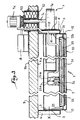
- Fig. 1 is an exploded perspective view of an infrared ray emitter according to the invention.
- Fig. 2 is a section along II-II (fig. 1).
- Fig. 3 is a horizontal section along III-III (Fig. 2) of an oven or the like inside which is installed an infrared ray emitter according to the invention.
- the infrared ray emitter shown in fig. 1 essentially comprises a box 1 produced in the form of an elongated parallelepiped closed on five of its faces, one of the large faces being open.
- a catalytic structure 2 is arranged in the open face 10 of the box 1.
- This structure is composed of an element 20 impregnated with a catalytic combustion material such as platinum.
- This element which is permeable to the gaseous mixture to be burned, consists of an inert support such as fiberglass or the like and capable of withstanding the high temperatures generated by catalytic combustion. We will not return to such a structure which is well known in practice.
- the element 20 is supported by a frame 21 fixed in a sealed manner relative to the open face 10 of the box 1. It can be seen that the frame 21 is associated with a frame 22 which determines a space corresponding to the section of the large open face 10 of the box 1.
- a spacer 23 whose ends are fixed to the frame 22 supports a member 24 injecting a combustible gas mixed with air and opening onto the inner face of the element 20, as is well known in practice.
- the spacer 23 also supports at least one electrical resistance 25 for preheating the impregnated element 20.
- the box 1 comprises two end flanges 11 and 12 which are respectively fixed to a console 4, 5.
- Each of these is provided with a ring of smooth holes 40, 50 in each of which a screw 3 can be engaged which is screwed into a threaded hole ccrrespondant 11, 12a of the flanges 11, 12.
- the bracket 5 is formed as a square, as will be explained better below.
- the console 5 is assembled to a support plate 6 on which the casing 7 has of an electric fan 7.
- the impeller 7 b of the electric fan which is located in the casing 7 a is wedged on one end of a shaft 7 c , the other end of which is assembled with the output shaft of the electric motor 7 d of the electric fan 7.
- the shaft 7 c is oriented perpendicular to the general direction of the box, as will be explained better below.
- the infrared radiation according to the invention is fixed by its brackets 4, 5 of the inner wall 9 has a partition 9 of an oven, suitably insulated tunnel or oven.
- the console 5 is fixed to the partition 9 by its right-angle part 52 which passes through the shaft 7c of the electric fan 7. The latter passes through this partition in a heat-tight manner by any appropriate means, in particular in a insulating sleeve 53.
- the pipe 24 has the injection member 24 supply fuel gas and the power conductors of the resistors 25 through a sealed manner to heat the partition wall 9.
- the tube 24 a and the conductors come from a control box 8 which is fixed to the outer wall 9 b of the partition 9, so as not to be exposed to the heat prevailing inside the oven or the like.
- the outlet orifice of the casing 7 has opens into a corresponding opening 60 of the support plate 6 which is centered on the longitudinal geometrical axis referenced X of the box 1.
- the console 5 Inside the ring of holes 50 , the console 5 has a passage 51 whose center is on the axis X.
- the flange 11 which has a central cutout 11 b corresponding to the passage 51.
- the flange 12 is full, that is to say, not drilled.
- the air sucked into the oven enclosure or the like is expelled inside the box 1 through the opening 60, the passage 51 and the cutout 11b in such a way that the box 1 constitutes a distribution chamber for the air expelled over the entire surface of the element 20.
- the design of the transmitter according to the invention allows its mounting in existing ovens or the like without significant modifications thereof and with a very simple installation.
- the air sent into the box 1 is that which is inside the oven or the like, the solvents emitted by the drying or polymerization of the paints are burnt at the level of the element 20 impregnated with 'a catalytic material, so that the gaseous medium contained by the oven is automatically recycled intensively.
- the one-piece transmitter according to the invention can withstand high temperatures, of the order of 250 ° C. .
Landscapes
- Engineering & Computer Science (AREA)
- Chemical & Material Sciences (AREA)
- Combustion & Propulsion (AREA)
- Mechanical Engineering (AREA)
- General Engineering & Computer Science (AREA)
- Chemical Kinetics & Catalysis (AREA)
- Life Sciences & Earth Sciences (AREA)
- Environmental & Geological Engineering (AREA)
- Microbiology (AREA)
- Sustainable Development (AREA)
- Gas Burners (AREA)
- Coating Apparatus (AREA)
- Application Of Or Painting With Fluid Materials (AREA)
Abstract
Description
- La présente invention est relative aux émetteurs de rayons infrarouges à brûleur catalytique et elle concerne plus particulièrement un tel appareil qui constitue un ensemble monobloc destiné à être installé dans un four ou analogue.
- On connaît de tels émetteurs de rayons infrarouges destinés à être installés dans des fours, des tunnels ou étuves destinés plus particulièrement au séchage ou à la polymérisation des peintures liquides ou en poudre sur des supports les plus divers.
- Suivant la technique connue, on dispose sur les parois internes des fours ou analogues des brûleurs catalytiques comportant chacun un cadre qui soutient une structure catalytique composée d'un élément imprégné d'une matière catalytique de combustion. A l'extérieur des cloisons des fours ainsi équipés, il est prévu des tuyauteries d'amenée du gaz combustible qui aboutissent dans chaque brûleur à un Venturi assurant le prémélange air/gaz, des conducteurs d'amenée du courant électrique pour les résistances de pré-chauffage des structures catalytiques et enfin des gaines destinées à diffuser de l'air engendré par un générateur d'air à turbine de manière à diffuser de l'air sur la surface des structures catalytiques.
- On comprend qu'une telle construction est complexe, de telle sorte qu'un four ou analogue ainsi équipé est d'un prix de revient très élevé.
- Les perfectionnements qui font l'objet de la présente invention visent à remédier à ces inconvénients et à permettre la réalisation d'un émetteur de rayons infrarouges à brûleur catalytique qui constitue un ensemble monobloc installé à l'intérieur d'un four ou analogue dont l'ensemble des composants permet un fonctionnement à des températures élevées, de l'ordre de 250°C, tout en comportant des moyens à recycler le milieu gazeux renfermé par le four par oxydation sans flamme des solvants dégagés par la peinture.
- A cet effet, l'émetteur de rayons infrarouges à brûleur catalytique suivant l'invention destiné à être installé dans un four ou analogue comprend :
- un caisson dont une grande face est ouverte ;
- une structure catalytique disposée dans la face ouverte du caisson ;
- un organe d'injection de gaz combustible ;
- un générateur d'air à turbine envoyant de l'air sous pression dans le caisson qui constitue chambre de distribution d'air sur toute la structure catalytique ;
- un système électrique de préchauffage de la structure catalytique.
- la turbine d'un générateur d'air, dont le dispositif d'entraînement est situé à l'extérieur du four, ainsi que les commandes électriques du système électrique de préchauffage.
- Suivant une forme de réalisation avantageuse, le caisson est monté entre deux consoles solidaires d'une des parois du four ou analogue, l'une des consoles étant assemblée à une embase à laquelle est fixée le carter de la turbine du générateur d'air. Cette turbine est calée sur un arbre qui traverse la paroi du four sur laquelle les consoles sont fixées pour coopérer à l'extérieur de celui-ci avec le dispositif d'entraînement de ladite turbine. De manière préférée, le caisson est monté orientable par rapport aux consoles.
- Le dessin annexé, donné à titre d'exemple, permettra de mieux comprendre l'invention, les caractéristiques qu'elle présente et les avantages qu'elle est susceptible de procurer :
- Fig. 1 est une vue éclatée en perspective d'un émetteur de rayon infrarouges conforme à l'invention.
- Fig. 2 en est une coupe suivant II-II (fig. 1).
- Fig. 3 est une coupe horizontale suivant III-III (fig. 2) d'un four ou analogue à l'intérieur duquel est installé un émetteur de rayons infrarouges suivant l'invention.
- L'émetteur de rayons infrarouges représenté en fig. 1 comprend essentiellement un caisson 1 réalisé sous la forme un parallélipipède allongé fermé sur cinq de ses faces, l'une 10 des grandes faces étant ouverte.
- Comme illustré en fig. 2, une structure catalytique 2 est disposée dans la face ouverte 10 du caisson 1. Cette structure est composée d'un élément 20 imprégné d'une matière catalytique de combustion telle que du platine. Cet élément, qui est perméable au mélange gazeux à brûler, est constitué d'un support inerte tel que de la fibre de verre ou analogue et propre à résister aux températures élevées engendrées par la combustion catalytique. On ne reviendra pas sur une telle structure qui est bien connue dans la pratique.
- L'élément 20 est soutenu par un cadre 21 fixé de manière étanche par rapport à la face ouverte 10 du caisson 1. On observe que le cadre 21 est associé à un châssis 22 qui détermine un espace correspondant à la section de la grande face ouverte 10 du caisson 1. Une entretoise 23 dont les extrémités sont fixées au châssis 22 soutient un organe 24 d'injection d'un gaz combustible mélangé à de l'air et débouchant sur la face intérieure de l'élément 20, comme cela est bien connu dans la pratique. L'entretoise 23 soutient encore au moins une résistance électrique 25 de préchauffage de l'élément imprégné 20.
- Comme illustré en fig. 1, le caisson 1 comporte deux flasques extrêmes 11 et 12 qui sont respectivement fixés à une console 4, 5. Chacune de celles-ci est munie d'une couronne de trous lisses 40, 50 dans chacun desquels on peut engager une vis 3 qui vient se visser dans un trou taraudé ccrrespondant 11a, 12a des flasques 11, 12. La console 5 est réalisée sous la forme d'une équerre, comme on l'expliquera mieux plus loin. La console 5 est assemblée à une plaque support 6 sur laquelle est monté le carter 7a d'un électro-ventilateur 7. Ainsi, en modifiant la position angulaire du caisson 1 par rapport aux consoles 4, 5 on peut orienter le caisson dans la direction souhaitée, comme illustré en traits discontinus en fig. 2. La turbine 7b de l'électro-ventilateur qui se trouve dans le carter 7a est calée sur l'une des extrémité d'un arbre 7c dont l'autre extrémité est assemblée à l'arbre de sortie du moteur électrique 7d de l'électroventilateur 7. L'arbre 7c est orienté perpendiculairement à la direction générale du caisson, comme on l'expliquera mieux plus loin.
- Comme illustré en fig. 3, l'émetteur de rayons infrarouges suivant l'invention est fixé par ses consoles 4, 5 sur la paroi interne 9a d'une cloison 9 d'un four, tunnel ou étuve convenablement calorifugée. La console 5 est fixée sur la cloison 9 par sa partie à angle droit 52 qui traversée par l'arbre 7c de l'électro-ventilateur 7. Ce dernier traverse cette cloison de manière étanche à la chaleur par tous moyens appropriés, notamment dans un manchon isolant 53. De même manière, le tuyau 24a d'alimentation de l'organe d'injection 24 de gaz combustible et les conducteurs d'alimentation électrique des résistances 25 traversent de manière étanche à la chaleur la cloison 9. Le tuyau 24a et les conducteurs sont issus d'un coffret de commande 8 qui est fixé sur la paroi extérieure 9b de la cloison 9, de manière à ne pas être exposés à la chaleur régnant à l'intérieur du four ou analogue.
- En revenant à fig. 1, on ccnstate que l'orifice de sortie du carter 7a débouche dans une ouverture correspondante 60 de la plaque support 6 qui est centrée sur l'axe géométrique longitudinal référencé X du caisson 1. A l'intérieur de la couronne de trous 50, la console 5 comporte un passage 51 dont le centre se trouve sur l'axe X. Il en va de même du flasque 11 qui comporte une découpe centrale 11b correspondant au passage 51. Par contre, le flasque 12 est plein, c'est-à-dire non percé. Ainsi, lorsque la turbine 7b de l'électro-ventilateur 7 est mise en route, l'air aspiré dans l'enceinte du four ou analogue est expulsé à l'intérieur du caisson 1 en traversant l'ouverture 60, le passage 51 et la découpe 11b de telle manière que le caisson 1 constitue une chambre de distribution de l'air expulsé sur toute la surface de l'élément 20.
- La conception de l'émetteur suivant l'invention permet son montage dans des fours ou analogues existants sans modifications importantes de ceux-ci et avec une mise en place très simple. De plus, du fait que l'air envoyé dans le caisson 1 est celui qui se trouve dans l'enceinte du four ou analogue, les solvants émis par le séchage ou la polymérisation des peintures sont brûlés au niveau de l'élément 20 imprégné d'une matière catalytique, si bien que le milieu gazeux renfermé par le four est recyclé automatiquement de manière intense.
- Enfin, par suite de la localisation des appareils délicats (moteur électrique, instruments de commande) hors de l'enceinte du four ou analogue, l'émetteur monobloc suivant l'invention peut supporter des températures élevées, de l'ordre de 250°C.
- Il doit d'ailleurs être entendu que la description qui précède n'a été donnée qu'à titre d'exemple et qu'elle ne limite nullement le domaine de l'invention dont on ne sortirait pas en remplaçant les détails d'exécution décrits par tous autres équivalents.
Claims (4)
- Emetteur de rayons infrarouges à brûleur catalytique destiné à être installé dans un four et comprenant :- un caisson dont une grande face est ouverte ;- une structure catalytique composée d'un élément imprégné d'une matière catalytique de combustion, placé dans un cadre lui-même disposé dans la face ouverte du caisson ;- un organe d'injection d'un gaz combustible situé dans le caisson et débouchant sur la face intérieure de l'élément imprégné, ledit organe étant alimenté en gaz par un tuyau ;- un générateur d'air à turbine envoyant de l'air sous pression dans le caisson qui constitue une chambre de distribution d'air sur toute la surface de l'élément imprégné ;- un système électrique de préchauffage de l'élément imprégné. ledit émetteur constituant un ensemble monobloc disposé dans le four et comportant des premiers moyens de fonctionner à des températures élevées de l'ordre de 250°C et des seconds moyens de recycler le milieu gazeux renfermé par le four.
- Emetteur de rayons infrarouges à brûleur catalytique suivant la revendication 1, dans lequel le dispositif d'entraînement de la turbine du générateur d'air et les commandes électriques du système électrique de préchauffage sont disposées à l'extérieur dudit four.
- Emetteur de rayons infrarouges à brûleur catalytique destiné à être installé dans un four ou analogue comprenant :- un caisson dont une grande face est ouverte ;- une structure catalytique composée d'un élément imprégné d'une matière catalytique de combustion, placé dans un cadre lui-même disposé dans la face ouverte du caisson ;- un organe d'injection d'un gaz combustible situé dans le caisson et débouchant sur la face intérieure de l'élément imprégné, ledit organe étant alimenté en gaz par un tuyau ;- un générateur d'air à turbine envoyant de l'air sous pression dans le caisson qui constitue une chambre de distribution d'air sur toute la surface de l'élément imprégné ;- un système électrique de préchauffage de l'élément imprégné ;- deux consoles solidaires d'une paroi interne du four, entre lesquelles le caisson est monté, l'une des consoles étant en outre assemblée à une embase à laquelle est fixé le carter de la turbine du générateur d'air, ladite turbine étant calée sur un arbre orienté perpendiculairement à la direction générale du caisson en vue de traverser la cloison sur laquelle les consoles sont fixées pour coopérer avec un moteur d'entraînement fixé à la face extérieure de ladite cloison, tandis que le tuyau d'alimentation en gaz et les conducteurs électriques du système de préchauffage traversent également la paroi pour aboutir à un coffret de commande fixé sur la face extérieure de ladite paroi.
- Emetteur de rayons infrarouges à brûleur catalytique suivant la revendication 3, dans lequel le caisson est monté orientable par rapport aux consoles.
Applications Claiming Priority (2)
| Application Number | Priority Date | Filing Date | Title |
|---|---|---|---|
| US504946 | 1995-07-20 | ||
| US08/504,946 US5586877A (en) | 1995-07-20 | 1995-07-20 | Infrared ray emitters with catalytic burner |
Publications (3)
| Publication Number | Publication Date |
|---|---|
| EP0754911A2 true EP0754911A2 (fr) | 1997-01-22 |
| EP0754911A3 EP0754911A3 (fr) | 1998-06-03 |
| EP0754911B1 EP0754911B1 (fr) | 2001-12-12 |
Family
ID=24008375
Family Applications (1)
| Application Number | Title | Priority Date | Filing Date |
|---|---|---|---|
| EP96420083A Expired - Lifetime EP0754911B1 (fr) | 1995-07-20 | 1996-03-14 | Emetteur de rayons infrarouges à brûleur catalytique |
Country Status (5)
| Country | Link |
|---|---|
| US (1) | US5586877A (fr) |
| EP (1) | EP0754911B1 (fr) |
| JP (1) | JP3098187B2 (fr) |
| AT (1) | ATE210798T1 (fr) |
| DE (1) | DE69617822T2 (fr) |
Cited By (4)
| Publication number | Priority date | Publication date | Assignee | Title |
|---|---|---|---|---|
| WO2013174383A1 (fr) * | 2012-05-21 | 2013-11-28 | Mærsk Olie Og Gas As | Séchage et cuisson sur site de systèmes de peinture utilisant des radiateurs à infrarouge catalytiques |
| WO2015107296A1 (fr) | 2014-01-16 | 2015-07-23 | Sunkiss Matherm Radiation | Ensemble de ventilation à recyclage d'air pour émetteur de rayonnements infrarouges avec contrôle de température |
| US9789514B2 (en) | 2008-05-08 | 2017-10-17 | Primetals Technologies France SAS | Method of drying and/or curing an organic coating on a continuously running metal strip, and device for implementing this method |
| CN110979871A (zh) * | 2019-10-23 | 2020-04-10 | 湖州市练市三峰线缆厂 | 一种漆包线自动包装线及其包装工艺 |
Families Citing this family (15)
| Publication number | Priority date | Publication date | Assignee | Title |
|---|---|---|---|---|
| FR2753461B1 (fr) * | 1996-09-19 | 1998-10-30 | Gerflor Sa | Procede et installation de fabrication d'une structure plastique composite, par exemple un revetement de sol |
| FR2791419B1 (fr) * | 1999-03-25 | 2001-05-04 | Sunkiss Aeronautique | Equipement d'emission surfacique d'un rayonnement infra-rouge, du type tunnel, comportant des dispositifs de combustion catalytique |
| US6521904B2 (en) * | 2000-12-15 | 2003-02-18 | Precision Combustion, Inc. | IR source, method and apparatus |
| DE102004006514A1 (de) * | 2004-02-10 | 2005-08-25 | Voith Paper Patent Gmbh | Verfahren zur Beheizung einer Walze sowie beheizbare Walze |
| PL1798470T3 (pl) * | 2005-12-13 | 2008-08-29 | Schwank Gmbh | Urządzenie grzewcze i sposób jego pracy |
| WO2007085251A1 (fr) * | 2006-01-26 | 2007-08-02 | Heatgear Professional Aps | Système chauffant catalytique portable pour un autoproducteur |
| US20080081306A1 (en) * | 2006-09-19 | 2008-04-03 | Kiosky Chung | Barbecue stove with two burners |
| US7717704B2 (en) * | 2007-03-28 | 2010-05-18 | Prince Castle, Inc. | Wire mesh burner plate for a gas oven burner |
| US8637792B2 (en) | 2011-05-18 | 2014-01-28 | Prince Castle, LLC | Conveyor oven with adjustable air vents |
| DE102012002865B4 (de) * | 2012-02-11 | 2021-06-10 | Gogas Goch Gmbh & Co. Kg | Verfahren zur energetischen Optimierung des Trocknungsprozesses von mit organisch-lösemittelhaltigen Stoffen behandelten Erzeugnissen |
| CN106287717A (zh) * | 2015-05-15 | 2017-01-04 | 张达积 | 红外线氢氧燃烧器 |
| CN106287639B (zh) * | 2015-05-15 | 2019-05-21 | 宁德市维克贸易有限公司 | 蒸汽变换氢氧预混清洁锅炉 |
| CN105509074B (zh) * | 2016-01-19 | 2017-12-26 | 周海波 | 漆膜烘干室燃气催化无焰加热voc处理系统 |
| CN106391420A (zh) * | 2016-10-31 | 2017-02-15 | 苏州格瑞涂装科技有限公司 | 一种天然气触媒催化燃烧中波红外辐射的加热固化方法及其设备 |
| CN108787378B (zh) * | 2017-05-12 | 2023-07-28 | 佛山宜可居新材料有限公司 | 一种用于人造板材表面的粉末涂料固化的设备及方法 |
Family Cites Families (9)
| Publication number | Priority date | Publication date | Assignee | Title |
|---|---|---|---|---|
| CA599739A (en) * | 1960-06-14 | N. Ipsen Harold | Heat treating furnace | |
| DE1254279B (de) * | 1962-11-23 | 1967-11-16 | Erhard Schwarze | OElbrenner |
| US3437085A (en) * | 1967-03-01 | 1969-04-08 | American Gas Ass | Self-cleaning gas oven system and gas burner means therefor |
| NL7314826A (fr) * | 1972-12-11 | 1974-06-13 | ||
| JPS5723716A (en) * | 1980-07-18 | 1982-02-08 | Matsushita Electric Ind Co Ltd | Combustor |
| JPS59199222A (ja) * | 1983-04-27 | 1984-11-12 | Sekisui Chem Co Ltd | 熱可塑性樹脂発泡体の製造方法およびその製造装置 |
| DE3916890A1 (de) * | 1988-05-31 | 1989-12-07 | Hagos Kachelofen Luftheizbauer | Gasheizvorrichtung fuer heizkammern, insbesondere gasheizsystem fuer kacheloefen |
| IE903998A1 (en) * | 1990-11-06 | 1992-05-22 | Advanced Ceramics Ltd | A catalytic heating element |
| US5203315A (en) * | 1992-08-18 | 1993-04-20 | Raytheon Company | Gas convection oven with dual function burner |
-
1995
- 1995-07-20 US US08/504,946 patent/US5586877A/en not_active Expired - Lifetime
-
1996
- 1996-03-14 EP EP96420083A patent/EP0754911B1/fr not_active Expired - Lifetime
- 1996-03-14 DE DE69617822T patent/DE69617822T2/de not_active Expired - Lifetime
- 1996-03-14 AT AT96420083T patent/ATE210798T1/de not_active IP Right Cessation
- 1996-04-02 JP JP08115190A patent/JP3098187B2/ja not_active Expired - Fee Related
Cited By (4)
| Publication number | Priority date | Publication date | Assignee | Title |
|---|---|---|---|---|
| US9789514B2 (en) | 2008-05-08 | 2017-10-17 | Primetals Technologies France SAS | Method of drying and/or curing an organic coating on a continuously running metal strip, and device for implementing this method |
| WO2013174383A1 (fr) * | 2012-05-21 | 2013-11-28 | Mærsk Olie Og Gas As | Séchage et cuisson sur site de systèmes de peinture utilisant des radiateurs à infrarouge catalytiques |
| WO2015107296A1 (fr) | 2014-01-16 | 2015-07-23 | Sunkiss Matherm Radiation | Ensemble de ventilation à recyclage d'air pour émetteur de rayonnements infrarouges avec contrôle de température |
| CN110979871A (zh) * | 2019-10-23 | 2020-04-10 | 湖州市练市三峰线缆厂 | 一种漆包线自动包装线及其包装工艺 |
Also Published As
| Publication number | Publication date |
|---|---|
| US5586877A (en) | 1996-12-24 |
| DE69617822D1 (de) | 2002-01-24 |
| EP0754911A3 (fr) | 1998-06-03 |
| DE69617822T2 (de) | 2002-08-14 |
| JP3098187B2 (ja) | 2000-10-16 |
| EP0754911B1 (fr) | 2001-12-12 |
| ATE210798T1 (de) | 2001-12-15 |
| JPH0929156A (ja) | 1997-02-04 |
Similar Documents
| Publication | Publication Date | Title |
|---|---|---|
| EP0754911B1 (fr) | Emetteur de rayons infrarouges à brûleur catalytique | |
| FR2595134A1 (fr) | Bruleur a gaz a soufflage d'air force pour un poele a bois | |
| FR2804496A1 (fr) | Bruleur a gaz a multiples couronnes de flammes | |
| FR2556547A1 (fr) | Generateur electrique perfectionne de rayons infrarouges constituant epurateur d'atmosphere | |
| BE902029A (fr) | Bruleur a gaz pour fourneaux et plans de cuisson en general. | |
| EP1640663A2 (fr) | Brûleur à gaz à flamme uniquement interne perfectionné | |
| EP1217302A1 (fr) | Dispositif chauffant radiant comportant une tête chauffante orientable | |
| EP0178198A2 (fr) | Brûleur à mélange préalable intégré et à flamme pilote intégrée | |
| EP1941207B1 (fr) | Bruleur/generateur d'air chaud a allumage interne | |
| FR2673268A1 (fr) | Four de cuisson electrique a usage domestique. | |
| EP1699330A1 (fr) | Procede d'allumage d'un appareil a combustible solide, et appareil permettant de mettre en oeuvre le procede | |
| FR2534005A1 (fr) | Agencement d'une chaudiere etanche a gaz a tirage force | |
| FR2505987A1 (fr) | Bruleur a gaz apte aux cuissons a basse temperature | |
| EP0998648B1 (fr) | Appareil de chauffage | |
| EP0064725A1 (fr) | Brûleur à gaz apte notamment aux cuissons à basse température | |
| FR3110608A1 (fr) | Appareil de sechage et/ou de lavage de linge equipe d’un système autonome d’extinction de feu | |
| FR2680226A1 (fr) | Dispositif de chauffage a gaz par rayonnement. | |
| EP0347383A2 (fr) | Appareil pour l'allumage de matières combustibles | |
| EP0663991A1 (fr) | Appareil et installation pour l'incineration de dechets. | |
| FR2500586A1 (fr) | Appareil d'eclairage a gaz | |
| EP1450101A1 (fr) | Conduit terminal pour conduit de cheminée à double paroi | |
| FR2763670A1 (fr) | Appareil de chauffage au gaz, notamment pour les batiments d'elevage | |
| FR2511755A2 (fr) | Bruleur a gaz apte aux cuissons a basse temperature | |
| FR2884594A1 (fr) | Bruleur/generateur d'air chaud a allumage interne | |
| CA2248174C (fr) | Appareil de chauffage |
Legal Events
| Date | Code | Title | Description |
|---|---|---|---|
| PUAI | Public reference made under article 153(3) epc to a published international application that has entered the european phase |
Free format text: ORIGINAL CODE: 0009012 |
|
| AK | Designated contracting states |
Kind code of ref document: A2 Designated state(s): AT BE DE ES FR GB IE IT NL SE |
|
| PUAL | Search report despatched |
Free format text: ORIGINAL CODE: 0009013 |
|
| AK | Designated contracting states |
Kind code of ref document: A3 Designated state(s): AT BE DE ES FR GB IE IT NL SE |
|
| 111L | Licence recorded |
Free format text: 980402 0100 A.C.I.R., SOCIETE ANONYME |
|
| 17P | Request for examination filed |
Effective date: 19980624 |
|
| 17Q | First examination report despatched |
Effective date: 20000512 |
|
| GRAG | Despatch of communication of intention to grant |
Free format text: ORIGINAL CODE: EPIDOS AGRA |
|
| GRAG | Despatch of communication of intention to grant |
Free format text: ORIGINAL CODE: EPIDOS AGRA |
|
| GRAH | Despatch of communication of intention to grant a patent |
Free format text: ORIGINAL CODE: EPIDOS IGRA |
|
| GRAH | Despatch of communication of intention to grant a patent |
Free format text: ORIGINAL CODE: EPIDOS IGRA |
|
| GRAA | (expected) grant |
Free format text: ORIGINAL CODE: 0009210 |
|
| AK | Designated contracting states |
Kind code of ref document: B1 Designated state(s): AT BE DE ES FR GB IE IT NL SE |
|
| PG25 | Lapsed in a contracting state [announced via postgrant information from national office to epo] |
Ref country code: NL Free format text: LAPSE BECAUSE OF FAILURE TO SUBMIT A TRANSLATION OF THE DESCRIPTION OR TO PAY THE FEE WITHIN THE PRESCRIBED TIME-LIMIT Effective date: 20011212 Ref country code: IT Free format text: LAPSE BECAUSE OF FAILURE TO SUBMIT A TRANSLATION OF THE DESCRIPTION OR TO PAY THE FEE WITHIN THE PRESCRIBED TIME-LIMIT;WARNING: LAPSES OF ITALIAN PATENTS WITH EFFECTIVE DATE BEFORE 2007 MAY HAVE OCCURRED AT ANY TIME BEFORE 2007. THE CORRECT EFFECTIVE DATE MAY BE DIFFERENT FROM THE ONE RECORDED. Effective date: 20011212 Ref country code: IE Free format text: LAPSE BECAUSE OF FAILURE TO SUBMIT A TRANSLATION OF THE DESCRIPTION OR TO PAY THE FEE WITHIN THE PRESCRIBED TIME-LIMIT Effective date: 20011212 Ref country code: GB Free format text: LAPSE BECAUSE OF FAILURE TO SUBMIT A TRANSLATION OF THE DESCRIPTION OR TO PAY THE FEE WITHIN THE PRESCRIBED TIME-LIMIT Effective date: 20011212 Ref country code: AT Free format text: LAPSE BECAUSE OF FAILURE TO SUBMIT A TRANSLATION OF THE DESCRIPTION OR TO PAY THE FEE WITHIN THE PRESCRIBED TIME-LIMIT Effective date: 20011212 |
|
| REF | Corresponds to: |
Ref document number: 210798 Country of ref document: AT Date of ref document: 20011215 Kind code of ref document: T |
|
| REG | Reference to a national code |
Ref country code: GB Ref legal event code: IF02 |
|
| REG | Reference to a national code |
Ref country code: IE Ref legal event code: FG4D Free format text: FRENCH |
|
| REF | Corresponds to: |
Ref document number: 69617822 Country of ref document: DE Date of ref document: 20020124 |
|
| PG25 | Lapsed in a contracting state [announced via postgrant information from national office to epo] |
Ref country code: SE Free format text: LAPSE BECAUSE OF FAILURE TO SUBMIT A TRANSLATION OF THE DESCRIPTION OR TO PAY THE FEE WITHIN THE PRESCRIBED TIME-LIMIT Effective date: 20020312 |
|
| PG25 | Lapsed in a contracting state [announced via postgrant information from national office to epo] |
Ref country code: BE Free format text: LAPSE BECAUSE OF NON-PAYMENT OF DUE FEES Effective date: 20020331 |
|
| NLV1 | Nl: lapsed or annulled due to failure to fulfill the requirements of art. 29p and 29m of the patents act | ||
| GBV | Gb: ep patent (uk) treated as always having been void in accordance with gb section 77(7)/1977 [no translation filed] |
Effective date: 20011212 |
|
| PG25 | Lapsed in a contracting state [announced via postgrant information from national office to epo] |
Ref country code: ES Free format text: LAPSE BECAUSE OF FAILURE TO SUBMIT A TRANSLATION OF THE DESCRIPTION OR TO PAY THE FEE WITHIN THE PRESCRIBED TIME-LIMIT Effective date: 20020627 |
|
| REG | Reference to a national code |
Ref country code: IE Ref legal event code: FD4D |
|
| BERE | Be: lapsed |
Owner name: *AJC Effective date: 20020331 |
|
| PLBE | No opposition filed within time limit |
Free format text: ORIGINAL CODE: 0009261 |
|
| STAA | Information on the status of an ep patent application or granted ep patent |
Free format text: STATUS: NO OPPOSITION FILED WITHIN TIME LIMIT |
|
| 26N | No opposition filed | ||
| NLV1 | Nl: lapsed or annulled due to failure to fulfill the requirements of art. 29p and 29m of the patents act | ||
| PGFP | Annual fee paid to national office [announced via postgrant information from national office to epo] |
Ref country code: DE Payment date: 20110329 Year of fee payment: 16 |
|
| REG | Reference to a national code |
Ref country code: DE Ref legal event code: R119 Ref document number: 69617822 Country of ref document: DE Effective date: 20121002 |
|
| REG | Reference to a national code |
Ref country code: FR Ref legal event code: TP Owner name: SUNKISS MATHERM RADIATION, FR Effective date: 20140404 Ref country code: FR Ref legal event code: CD Owner name: SUNKISS MATHERM RADIATION, FR Effective date: 20140404 Ref country code: FR Ref legal event code: CA Effective date: 20140404 |
|
| PG25 | Lapsed in a contracting state [announced via postgrant information from national office to epo] |
Ref country code: DE Free format text: LAPSE BECAUSE OF NON-PAYMENT OF DUE FEES Effective date: 20121002 |
|
| REG | Reference to a national code |
Ref country code: FR Ref legal event code: PLFP Year of fee payment: 20 |
|
| PGFP | Annual fee paid to national office [announced via postgrant information from national office to epo] |
Ref country code: FR Payment date: 20150130 Year of fee payment: 20 |