EP0756370A2 - Convertisseur résonant avec domaine de charge étendu - Google Patents
Convertisseur résonant avec domaine de charge étendu Download PDFInfo
- Publication number
- EP0756370A2 EP0756370A2 EP96305168A EP96305168A EP0756370A2 EP 0756370 A2 EP0756370 A2 EP 0756370A2 EP 96305168 A EP96305168 A EP 96305168A EP 96305168 A EP96305168 A EP 96305168A EP 0756370 A2 EP0756370 A2 EP 0756370A2
- Authority
- EP
- European Patent Office
- Prior art keywords
- switching devices
- main
- resonant
- auxiliary
- bridge
- Prior art date
- Legal status (The legal status is an assumption and is not a legal conclusion. Google has not performed a legal analysis and makes no representation as to the accuracy of the status listed.)
- Granted
Links
- 230000010363 phase shift Effects 0.000 claims abstract description 8
- 238000004088 simulation Methods 0.000 description 5
- 239000003990 capacitor Substances 0.000 description 4
- 238000000034 method Methods 0.000 description 3
- 238000004804 winding Methods 0.000 description 2
- 230000020169 heat generation Effects 0.000 description 1
- 230000010355 oscillation Effects 0.000 description 1
- 230000003071 parasitic effect Effects 0.000 description 1
Images


Classifications
-
- H—ELECTRICITY
- H02—GENERATION; CONVERSION OR DISTRIBUTION OF ELECTRIC POWER
- H02M—APPARATUS FOR CONVERSION BETWEEN AC AND AC, BETWEEN AC AND DC, OR BETWEEN DC AND DC, AND FOR USE WITH MAINS OR SIMILAR POWER SUPPLY SYSTEMS; CONVERSION OF DC OR AC INPUT POWER INTO SURGE OUTPUT POWER; CONTROL OR REGULATION THEREOF
- H02M1/00—Details of apparatus for conversion
- H02M1/44—Circuits or arrangements for compensating for electromagnetic interference in converters or inverters
-
- H—ELECTRICITY
- H02—GENERATION; CONVERSION OR DISTRIBUTION OF ELECTRIC POWER
- H02M—APPARATUS FOR CONVERSION BETWEEN AC AND AC, BETWEEN AC AND DC, OR BETWEEN DC AND DC, AND FOR USE WITH MAINS OR SIMILAR POWER SUPPLY SYSTEMS; CONVERSION OF DC OR AC INPUT POWER INTO SURGE OUTPUT POWER; CONTROL OR REGULATION THEREOF
- H02M3/00—Conversion of DC power input into DC power output
- H02M3/22—Conversion of DC power input into DC power output with intermediate conversion into AC
- H02M3/24—Conversion of DC power input into DC power output with intermediate conversion into AC by static converters
- H02M3/28—Conversion of DC power input into DC power output with intermediate conversion into AC by static converters using discharge tubes with control electrode or semiconductor devices with control electrode to produce the intermediate AC
- H02M3/325—Conversion of DC power input into DC power output with intermediate conversion into AC by static converters using discharge tubes with control electrode or semiconductor devices with control electrode to produce the intermediate AC using devices of a triode or a transistor type requiring continuous application of a control signal
- H02M3/335—Conversion of DC power input into DC power output with intermediate conversion into AC by static converters using discharge tubes with control electrode or semiconductor devices with control electrode to produce the intermediate AC using devices of a triode or a transistor type requiring continuous application of a control signal using semiconductor devices only
- H02M3/337—Conversion of DC power input into DC power output with intermediate conversion into AC by static converters using discharge tubes with control electrode or semiconductor devices with control electrode to produce the intermediate AC using devices of a triode or a transistor type requiring continuous application of a control signal using semiconductor devices only in push-pull configuration
- H02M3/3372—Conversion of DC power input into DC power output with intermediate conversion into AC by static converters using discharge tubes with control electrode or semiconductor devices with control electrode to produce the intermediate AC using devices of a triode or a transistor type requiring continuous application of a control signal using semiconductor devices only in push-pull configuration of the parallel type
-
- H—ELECTRICITY
- H02—GENERATION; CONVERSION OR DISTRIBUTION OF ELECTRIC POWER
- H02M—APPARATUS FOR CONVERSION BETWEEN AC AND AC, BETWEEN AC AND DC, OR BETWEEN DC AND DC, AND FOR USE WITH MAINS OR SIMILAR POWER SUPPLY SYSTEMS; CONVERSION OF DC OR AC INPUT POWER INTO SURGE OUTPUT POWER; CONTROL OR REGULATION THEREOF
- H02M7/00—Conversion of AC power input into DC power output; Conversion of DC power input into AC power output
- H02M7/42—Conversion of DC power input into AC power output without possibility of reversal
- H02M7/44—Conversion of DC power input into AC power output without possibility of reversal by static converters
- H02M7/48—Conversion of DC power input into AC power output without possibility of reversal by static converters using discharge tubes with control electrode or semiconductor devices with control electrode
- H02M7/53—Conversion of DC power input into AC power output without possibility of reversal by static converters using discharge tubes with control electrode or semiconductor devices with control electrode using devices of a triode or transistor type requiring continuous application of a control signal
- H02M7/537—Conversion of DC power input into AC power output without possibility of reversal by static converters using discharge tubes with control electrode or semiconductor devices with control electrode using devices of a triode or transistor type requiring continuous application of a control signal using semiconductor devices only, e.g. single switched pulse inverters
- H02M7/5387—Conversion of DC power input into AC power output without possibility of reversal by static converters using discharge tubes with control electrode or semiconductor devices with control electrode using devices of a triode or transistor type requiring continuous application of a control signal using semiconductor devices only, e.g. single switched pulse inverters in a bridge configuration
-
- Y—GENERAL TAGGING OF NEW TECHNOLOGICAL DEVELOPMENTS; GENERAL TAGGING OF CROSS-SECTIONAL TECHNOLOGIES SPANNING OVER SEVERAL SECTIONS OF THE IPC; TECHNICAL SUBJECTS COVERED BY FORMER USPC CROSS-REFERENCE ART COLLECTIONS [XRACs] AND DIGESTS
- Y02—TECHNOLOGIES OR APPLICATIONS FOR MITIGATION OR ADAPTATION AGAINST CLIMATE CHANGE
- Y02B—CLIMATE CHANGE MITIGATION TECHNOLOGIES RELATED TO BUILDINGS, e.g. HOUSING, HOUSE APPLIANCES OR RELATED END-USER APPLICATIONS
- Y02B70/00—Technologies for an efficient end-user side electric power management and consumption
- Y02B70/10—Technologies improving the efficiency by using switched-mode power supplies [SMPS], i.e. efficient power electronics conversion e.g. power factor correction or reduction of losses in power supplies or efficient standby modes
-
- Y—GENERAL TAGGING OF NEW TECHNOLOGICAL DEVELOPMENTS; GENERAL TAGGING OF CROSS-SECTIONAL TECHNOLOGIES SPANNING OVER SEVERAL SECTIONS OF THE IPC; TECHNICAL SUBJECTS COVERED BY FORMER USPC CROSS-REFERENCE ART COLLECTIONS [XRACs] AND DIGESTS
- Y02—TECHNOLOGIES OR APPLICATIONS FOR MITIGATION OR ADAPTATION AGAINST CLIMATE CHANGE
- Y02P—CLIMATE CHANGE MITIGATION TECHNOLOGIES IN THE PRODUCTION OR PROCESSING OF GOODS
- Y02P80/00—Climate change mitigation technologies for sector-wide applications
- Y02P80/10—Efficient use of energy, e.g. using compressed air or pressurized fluid as energy carrier
Definitions
- the present invention relates generally to power converters and, more particularly, to a resonant converter with auxiliary circuitry for achieving high efficiency operation over a wide load range.
- Loss of zero-voltage switching capability i.e., switching active switching devices with substantially zero voltage thereacross
- a resonant converter e.g., a series resonant converter or a phase-shifted series resonant converter
- EMI electromagnetic interference
- problems in controlling output voltage are typically solved by adding one or more reactive components to the resonant circuit for storing some reactive energy.
- such an approach significantly changes the control characteristics of the converter such that the converter control is very complex and results in a loss of output voltage control.
- the additional reactive energy is circulated through the converter at heavy loads, leading to an increase in conduction losses and a reduction in efficiency.
- An embodiment of the resonant converter comprises a full-bridge or half-bridge connection of main switching devices, each switching device having a snubber capacitor and an antiparallel diode coupled thereacross, and a resonant circuit coupled to the main switching devices.
- There is an auxiliary circuit corresponding to each half-bridge connection of main switching devices each auxiliary circuit comprising a half-bridge connection of auxiliary switching devices with the junction therebetween coupled to the junction between the main switching devices of the corresponding half-bridge.
- ZVS zero-voltage switching
- the resonant converter operates with high efficiency and low EMI over a wide load range, and allows phase-shifted pulse width modulation and frequency control over a wide load range without loss of ZVS capability.
- the control characteristics of the resonant converter are unaltered.
- FIG. 1 illustrates a resonant converter 10 with auxiliary circuits 12 and 14 according to the present invention.
- the resonant converter 10 comprises a conventional resonant converter 11 comprising main switching devices Q1, Q2, Q3 and Q4 connected as shown in a full-bridge configuration, each switch having a snubber capacitor C1-C4, respectively, and an antiparallel diode (which may he an integral device) D1-D4, respectively, coupled thereacross.
- the resonant converter 11 comprises a resonant circuit 13, which is illustrated in FIG.
- the load circuit is connected to the secondary winding of transformer T at points c and d, as shown, and comprises a parallel connection of a full-wave rectifier 16, a filter capacitor Cf, and a load 18.
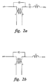
- FIG. 1 A series resonant converter is illustrated in FIG. 1 by way of example only since the principles of the present invention apply equally to other types of resonant circuits, including, for example, a series/parallel resonant circuit and a parallel resonant circuit, as illustrated in FIGS. 2A and 2B, respectively.
- switching frequency control There are basically two conventional resonant converter control methods. The more common of the two is switching frequency control. The problem with switching frequency control is that, at light loads, output voltage control can only be maintained if the switching frequency is increased to very high values (which is usually not practicable in the series resonant converter of FIG. 1).
- the second conventional type of control useful in a full-bridge resonant converter is phase-shifted pulse width modulation (PSPWM) wherein the switching frequency is fixed, but the phase shift between the two half-bridges is varied. In this way, the pulse width of the voltage between junctions a and b is modified to effectively provide output voltage control by PWM.
- PSPWM phase-shifted pulse width modulation
- the main problem of PSPWM control is loss of zero-voltage switching (ZVS) at light loads. When ZVS is lost, switching losses increase and excessive EMI is generated.
- ZVS zero-voltage switching
- the control characteristics of the converter are influenced by parasitic oscillations caused by hard switching.
- auxiliary circuitry In accordance with the present invention, the problems of the conventional resonant converter control methods, described hereinabove, are overcome by adding auxiliary circuitry.
- two auxiliary circuits 12 and 14 are added.
- Each auxiliary circuit comprises a half-bridge connection of low-current auxiliary switching devices Qx1-Qx4 and Qx3-Qx2, respectively; the junction between the switching devices of each auxiliary half-bridge is connected to a corresponding one of the junctions a and b, respectively, between the main switching devices Q1-Q4 and Q3-Q2, respectively, of the series resonant converter.
- the current rating of the auxiliary components is typically significantly less than the current rating (e.g., less than 10%) of the main switching devices and resonant inductor in the series resonant converter.
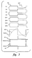
- FIG. 3 illustrates gate drive signals for switching devices Q1-Q4 and Qx1-Qx4 and converter waveforms for a series resonant converter with auxiliary circuitry in accordance with the present invention, such as that of FIG. 1, under heavy load conditions.
- the main bridge voltage v(a,b) and the resonant inductor current waveforms are the same as for a conventional series resonant converter.
- At heavy loads there is plenty of energy stored in the resonant inductor Lr, and this energy is used to commutate nodes a and b in resonant fashion, thus providing ZVS operation for switching devices Q1-Q4.
- auxiliary inductor currents ix1 and ix2 are kept at a very low level, typically below 2% of the resonant inductor current and are sufficient only to commutate the nodes ax and bx and provide ZVS conditions for the auxiliary switching devices.
- FIG. 4 illustrates gate drive signals for switching devices Q1-Q4 and Qx1-Qx4 and converter waveforms for a series resonant converter with auxiliary circuits in accordance with the present invention, such as that of FIG. 1, under light load conditions.
- operation of the main series resonant converter bridge is essentially the same as conventional phase-shifted PWM.
- the current iLR is not sufficient to commutate nodes a and b.
- phase shift between the corresponding main and auxiliary switching devices i.e., v(ax,a) and v(bx,b)
- the currents ix1 and ix2 are increased to a level sufficient for the sum of the currents iLR and ix1 (or ix2) to provide ZVS for all the bridge switching devices.
- FIG. 5 illustrates simulation results for the converter of FIG. 1 operating at an input voltage of 400 V, an output voltage of 80 kV, and an output current of 1250 mA
- FIG. 6 illustrates simulation results for the converter of FIG. 1 operating at an input voltage of 400 V, an output voltage of 150 kV, and an output current of 10 mA.
- the parameters of a high voltage transformer were used for transformer T, including leakage inductance and winding capacitance.
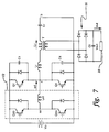
- FIG. 7 illustrates an alternative embodiment of a resonant converter including auxiliary circuitry according to the present invention comprising a half-bridge connection of main switching devices Q1 and Q4 and a single auxiliary half-bridge circuit with auxiliary switching devices Qx1 and Qx4.
- the output of the half-bridge resonant converter is controlled by frequency control, and the phase between the auxiliary switching devices and the main switching devices is varied in order to maintain ZVS at light loads.
- a resonant converter with auxiliary circuitry in accordance with the present invention operates with high efficiency and low EMI over a wide load range, and allows phase-shifted pulse width modulation and frequency control over a wide load range without loss of ZVS capability.
- the control characteristics of the resonant converter are virtually unchanged.
Landscapes
- Engineering & Computer Science (AREA)
- Power Engineering (AREA)
- Physics & Mathematics (AREA)
- Electromagnetism (AREA)
- Dc-Dc Converters (AREA)
- Inverter Devices (AREA)
Applications Claiming Priority (2)
| Application Number | Priority Date | Filing Date | Title |
|---|---|---|---|
| US08/506,312 US5546294A (en) | 1995-07-24 | 1995-07-24 | Resonant converter with wide load range |
| US506312 | 2000-02-17 |
Publications (3)
| Publication Number | Publication Date |
|---|---|
| EP0756370A2 true EP0756370A2 (fr) | 1997-01-29 |
| EP0756370A3 EP0756370A3 (fr) | 1997-06-11 |
| EP0756370B1 EP0756370B1 (fr) | 2001-11-21 |
Family
ID=24014083
Family Applications (1)
| Application Number | Title | Priority Date | Filing Date |
|---|---|---|---|
| EP96305168A Expired - Lifetime EP0756370B1 (fr) | 1995-07-24 | 1996-07-12 | Convertisseur résonant avec domaine de charge étendu |
Country Status (4)
| Country | Link |
|---|---|
| US (1) | US5546294A (fr) |
| EP (1) | EP0756370B1 (fr) |
| JP (1) | JPH09117156A (fr) |
| DE (1) | DE69617128T2 (fr) |
Cited By (4)
| Publication number | Priority date | Publication date | Assignee | Title |
|---|---|---|---|---|
| US6072856A (en) * | 1997-06-12 | 2000-06-06 | U.S. Phillips Corporation | Power supply unit including a pulse width modulated inverter, notably for an x-ray generator |
| WO2014033013A3 (fr) * | 2012-08-29 | 2014-10-30 | Schmidhauser Ag | Convertisseur continu-continu |
| EP1976108A3 (fr) * | 2007-03-27 | 2016-01-27 | Astrium GmbH | Convertisseur, en particulier pour une turbine à ions |
| EP1998432A3 (fr) * | 2007-05-30 | 2016-06-15 | Delphi Technologies, Inc. | Procédé de contrôle de séquence de commutation pour un convertisseur de pont PS-ZVT |
Families Citing this family (48)
| Publication number | Priority date | Publication date | Assignee | Title |
|---|---|---|---|---|
| DE69523752T2 (de) * | 1995-08-31 | 2002-08-29 | St Microelectronics Srl | Verfahren und Schaltung zur pulsbreitenmodulierten Steuerung einer Brücke und eines Plattenantriebs und unter Verwendung derselben |
| US5773966A (en) * | 1995-11-06 | 1998-06-30 | General Electric Company | Dual-mode, high-efficiency dc-dc converter useful for portable battery-operated equipment |
| JP3531385B2 (ja) * | 1996-10-28 | 2004-05-31 | ソニー株式会社 | 電源装置 |
| KR100224103B1 (ko) * | 1996-12-14 | 1999-10-15 | 윤종용 | 공진형 전원 스위치장치 |
| US5986895A (en) * | 1998-06-05 | 1999-11-16 | Astec International Limited | Adaptive pulse width modulated resonant Class-D converter |
| DE69940902D1 (de) * | 1998-12-08 | 2009-07-02 | Panasonic Corp | Schaltnetzteil |
| JP2001025259A (ja) * | 1999-07-05 | 2001-01-26 | Tdk Corp | Pwmインバーター装置 |
| US6246594B1 (en) | 1999-07-23 | 2001-06-12 | Shindengen Electric Manufacturing Co., Ltd. | Switching power supply having low loss characteristics |
| US6166528A (en) * | 1999-11-02 | 2000-12-26 | Fairchild Semiconductor Corporation | Lossless current sensing in buck converters working with low duty cycles and high clock frequencies |
| US6381150B2 (en) * | 1999-11-19 | 2002-04-30 | Iwatt | Isolated dual converter having primary side internal feedback for output regulation |
| US6163140A (en) * | 2000-02-01 | 2000-12-19 | Micrel Incorporated | Start-up circuit for voltage regulators |
| AU2001242322A1 (en) * | 2000-04-03 | 2001-10-15 | Aalborg Universitet | A resonant converter |
| US6504739B2 (en) | 2001-05-18 | 2003-01-07 | Astec International Limited | Simple control circuit for synchronous rectifiers used in ZVS phase shifted full bridge converter |
| AU2002339815A1 (en) * | 2001-05-21 | 2002-12-03 | Marconi Intellectual Property (Ringfence) Inc. | Power systems power circuits and components for power systems |
| JP4017490B2 (ja) * | 2002-10-02 | 2007-12-05 | 株式会社デンソー | Dc/dcコンバータ |
| US20040239401A1 (en) * | 2003-05-27 | 2004-12-02 | Chi-Shun Liao | Zero-voltage-switching full-bridge converter |
| US6909617B1 (en) * | 2004-01-22 | 2005-06-21 | La Marche Manufacturing Co. | Zero-voltage-switched, full-bridge, phase-shifted DC-DC converter with improved light/no-load operation |
| FR2866491B1 (fr) * | 2004-02-12 | 2006-06-02 | Air Liquide | Onduleur quasi resonnant a commutation douce, convertisseur de tension et poste de soudage l'utilisant |
| US7307475B2 (en) * | 2004-05-28 | 2007-12-11 | Ixys Corporation | RF generator with voltage regulator |
| DE102006022819A1 (de) * | 2005-05-23 | 2007-01-04 | Infineon Technologies Ag | Schaltungsanordnung zum Versorgen einer Last mit einem Ausgangsstrom |
| DE102006022845B4 (de) * | 2005-05-23 | 2016-01-07 | Infineon Technologies Ag | Ansteuerschaltung für eine Schaltereinheit einer getakteten Leistungsversorgungsschaltung und Resonanzkonverter |
| JP4797663B2 (ja) * | 2006-02-03 | 2011-10-19 | Tdk株式会社 | スイッチング電源装置 |
| JP5105819B2 (ja) * | 2006-10-05 | 2012-12-26 | 河村電器産業株式会社 | Dc−dcコンバータ |
| US7869237B1 (en) | 2007-12-27 | 2011-01-11 | Lockheed Martin Corporation | Phase-shifted bridge with auxiliary circuit to maintain zero-voltage-switching |
| US7796405B2 (en) * | 2008-04-07 | 2010-09-14 | Dell Products, Lp | Phase shifted DC-DC converter with improved efficiency at light load |
| WO2009156230A2 (fr) * | 2008-06-25 | 2009-12-30 | Siemens Ag Österreich | Onduleur et procédé de fonctionnement de l'onduleur |
| US7859870B1 (en) | 2008-07-29 | 2010-12-28 | Lockheed Martin Corporation | Voltage clamps for energy snubbing |
| US7742573B2 (en) * | 2008-10-17 | 2010-06-22 | General Electric Company | Fast switching circuit for x-ray imaging applications |
| IT1392841B1 (it) * | 2008-12-29 | 2012-03-23 | Alenia Aeronautica Spa | Disposizione circuitale per la conversione attiva di potenza, basata su una configurazione di convertitore a commutazione risonante |
| EP2209197A1 (fr) * | 2009-01-16 | 2010-07-21 | Whirpool Corporation | Procédé de contrôle de convertisseurs de puissance résonants dans des systèmes de chauffage par induction et système de chauffage par induction pour réaliser ledit procédé |
| DE112009004565B4 (de) * | 2009-04-27 | 2019-10-17 | Hewlett Packard Enterprise Development Lp | Umwandlungssystem für elektrische leistung mit einem anpassbaren transformatorwindungsverhältnis für verbesserte effizienz |
| CN102931843B (zh) * | 2011-08-09 | 2015-02-11 | 陈仲 | 自驱动有源辅助网络的软开关全桥直流变换器 |
| CN102594179B (zh) * | 2012-01-19 | 2014-08-20 | 华为技术有限公司 | 逆变器电路及其控制方法、逆变器电路控制装置 |
| CN102570872A (zh) * | 2012-02-23 | 2012-07-11 | 石家庄通合电子有限公司 | 一种单相并网逆变电路 |
| JP2014079150A (ja) * | 2012-09-19 | 2014-05-01 | Toshiba Corp | 電磁機器駆動システム及びモータ駆動車両 |
| US9595888B2 (en) * | 2012-11-29 | 2017-03-14 | General Electric Company | System and method to avoid reverse recovery in a power converter |
| US9515562B2 (en) * | 2013-03-05 | 2016-12-06 | Futurewei Technologies, Inc. | LLC resonant converters |
| US9119592B2 (en) | 2013-09-03 | 2015-09-01 | General Electric Company | Interleaved resonant converter |
| JP2015095988A (ja) * | 2013-11-13 | 2015-05-18 | 株式会社東芝 | Dc−dcコンバータ |
| US9712066B2 (en) * | 2014-06-02 | 2017-07-18 | Utah State University | Assisted zero voltage switching for a DC-to-DC converter |
| JP6331791B2 (ja) * | 2014-07-10 | 2018-05-30 | 株式会社デンソー | 電力変換装置、及び非接触給電システム |
| JP6331793B2 (ja) * | 2014-07-11 | 2018-05-30 | 株式会社デンソー | 電力変換装置、及び非接触給電システム |
| US9584117B1 (en) | 2016-03-21 | 2017-02-28 | Toyota Motor Engineering & Manufacturing North America, Inc. | Hybrid resonant driver for sic MOSFET |
| JP7144591B2 (ja) * | 2017-12-04 | 2022-09-29 | ローム株式会社 | 電力変換装置 |
| TWI671984B (zh) | 2018-11-14 | 2019-09-11 | 群光電能科技股份有限公司 | 電源供應裝置 |
| JP2021072730A (ja) * | 2019-10-31 | 2021-05-06 | 新電元工業株式会社 | 電源装置および電源装置の制御方法 |
| JP7372178B2 (ja) * | 2020-03-06 | 2023-10-31 | 新電元工業株式会社 | 電源装置 |
| US20250367748A1 (en) * | 2024-05-29 | 2025-12-04 | The Esab Group, Inc. | Manipulation of resonant elements in switching power supplies |
Family Cites Families (4)
| Publication number | Priority date | Publication date | Assignee | Title |
|---|---|---|---|---|
| US4916599A (en) * | 1989-03-29 | 1990-04-10 | Hyperpower, Inc. | Switching power supply |
| US4992919A (en) * | 1989-12-29 | 1991-02-12 | Lee Chu Quon | Parallel resonant converter with zero voltage switching |
| US5267138A (en) * | 1992-03-23 | 1993-11-30 | Creos International Ltd. | Driving and clamping power regulation technique for continuous, in-phase, full-duration, switch-mode resonant converter power supply |
| US5479337A (en) * | 1993-11-30 | 1995-12-26 | Kaiser Aerospace And Electronics Corporation | Very low power loss amplifier for analog signals utilizing constant-frequency zero-voltage-switching multi-resonant converter |
-
1995
- 1995-07-24 US US08/506,312 patent/US5546294A/en not_active Expired - Fee Related
-
1996
- 1996-07-12 EP EP96305168A patent/EP0756370B1/fr not_active Expired - Lifetime
- 1996-07-12 DE DE69617128T patent/DE69617128T2/de not_active Expired - Fee Related
- 1996-07-16 JP JP8185240A patent/JPH09117156A/ja not_active Withdrawn
Non-Patent Citations (2)
| Title |
|---|
| PROCEEDINGS OF THE ANNUAL APPLIED POWER ELECTRONICS CONFERENCE AND EXPOSITION (APEC), ORLANDO, FEB. 13 - 17, 1994, vol. 1, 13 February 1994, INSTITUTE OF ELECTRICAL AND ELECTRONICS ENGINEERS, pages 143-149, XP000467312 CHO J G ET AL: "NOVEL FULL BRIDGE ZERO-VOLTAGE-TRANSITION PWM DC-DC CONVERTER FOR HIGH POWER APPLICATIONS" * |
| PROCEEDINGS OF THE ANNUAL POWER ELECTRONICS SPECIALISTS CONFERENCE (PESC), SEATTLE, JUNE 20 - 25, 1993, no. CONF. 24, 20 June 1993, INSTITUTE OF ELECTRICAL AND ELECTRONICS ENGINEERS, pages 165-170, XP000399443 HAMADA S ET AL: "AN IMPROVED SOFT-SWITCHING PWM FULL-BRIDGE DC-DC CONVERTER MODIFICATION OPERATING AT REDUCED CONDUCTION LOSS" * |
Cited By (4)
| Publication number | Priority date | Publication date | Assignee | Title |
|---|---|---|---|---|
| US6072856A (en) * | 1997-06-12 | 2000-06-06 | U.S. Phillips Corporation | Power supply unit including a pulse width modulated inverter, notably for an x-ray generator |
| EP1976108A3 (fr) * | 2007-03-27 | 2016-01-27 | Astrium GmbH | Convertisseur, en particulier pour une turbine à ions |
| EP1998432A3 (fr) * | 2007-05-30 | 2016-06-15 | Delphi Technologies, Inc. | Procédé de contrôle de séquence de commutation pour un convertisseur de pont PS-ZVT |
| WO2014033013A3 (fr) * | 2012-08-29 | 2014-10-30 | Schmidhauser Ag | Convertisseur continu-continu |
Also Published As
| Publication number | Publication date |
|---|---|
| JPH09117156A (ja) | 1997-05-02 |
| US5546294A (en) | 1996-08-13 |
| DE69617128D1 (de) | 2002-01-03 |
| DE69617128T2 (de) | 2002-08-22 |
| EP0756370B1 (fr) | 2001-11-21 |
| EP0756370A3 (fr) | 1997-06-11 |
Similar Documents
| Publication | Publication Date | Title |
|---|---|---|
| EP0756370B1 (fr) | Convertisseur résonant avec domaine de charge étendu | |
| Hua et al. | An improved full-bridge zero-voltage-switched PWM converter using a saturable inductor | |
| US6310785B1 (en) | Zero voltage switching DC-DC converter | |
| US6356462B1 (en) | Soft-switched full-bridge converters | |
| US5796598A (en) | Voltage-converting circuit for the power supply of an electrical consumer of high output, particularly a bobbin winding machine | |
| US5442540A (en) | Soft-switching PWM converters | |
| Lee et al. | Novel zero-voltage-transition and zero-current-transition pulse-width-modulation converters | |
| US5646835A (en) | Series resonant converter | |
| CA2837698C (fr) | Alimentation electrique a mode resonant dotee d'un inducteur a enroulements multiples | |
| Garcia et al. | An optimized DC-to-DC converter topology for high-voltage pulse-load applications | |
| Kollipara et al. | Phase control and power optimization of LLC converter | |
| Kutkut | A full bridge soft switched telecom power supply with a current doubler rectifier | |
| CA3122390A1 (fr) | Convertisseur de puissance resonant | |
| US5701243A (en) | High-power factor series resonant rectifier circuit | |
| Bendre et al. | New high power DC-DC converter with loss limited switching and lossless secondary clamp | |
| Rajeev | An input current shaper with boost and flyback converter using integrated magnetics | |
| García et al. | Using the hybrid series-parallel resonant converter with capacitive output filter and with PWM phase-shifted control for high-voltage applications | |
| US20010042739A1 (en) | Arc welding generator with input voltage adapting regulator stage | |
| Filba-Martinez et al. | Modulation and capacitor voltage balancing control of a four-level active-clamped dual-active-bridge DC-DC converter | |
| KR102959127B1 (ko) | 공진 전력 변환기 | |
| RU2830228C2 (ru) | Резонансный преобразователь мощности | |
| KR102914819B1 (ko) | 넓은 전압 범위 대응이 가능한 고효율 psfb 컨버터 | |
| Chauhan et al. | Active Clamped Dual Current-Fed Bidirectional DC-DC Converter for Wide Voltage Range Applications | |
| KR20190090661A (ko) | 풀-브릿지 컨버터 구동용 3탭 출력을 가진 dc/dc 플라이백 컨버터 | |
| Foch et al. | DC and slow pulsed converter topologies |
Legal Events
| Date | Code | Title | Description |
|---|---|---|---|
| PUAI | Public reference made under article 153(3) epc to a published international application that has entered the european phase |
Free format text: ORIGINAL CODE: 0009012 |
|
| AK | Designated contracting states |
Kind code of ref document: A2 Designated state(s): DE NL |
|
| PUAL | Search report despatched |
Free format text: ORIGINAL CODE: 0009013 |
|
| AK | Designated contracting states |
Kind code of ref document: A3 Designated state(s): DE NL |
|
| 17P | Request for examination filed |
Effective date: 19971211 |
|
| 17Q | First examination report despatched |
Effective date: 19980925 |
|
| GRAG | Despatch of communication of intention to grant |
Free format text: ORIGINAL CODE: EPIDOS AGRA |
|
| GRAG | Despatch of communication of intention to grant |
Free format text: ORIGINAL CODE: EPIDOS AGRA |
|
| GRAH | Despatch of communication of intention to grant a patent |
Free format text: ORIGINAL CODE: EPIDOS IGRA |
|
| GRAH | Despatch of communication of intention to grant a patent |
Free format text: ORIGINAL CODE: EPIDOS IGRA |
|
| GRAA | (expected) grant |
Free format text: ORIGINAL CODE: 0009210 |
|
| AK | Designated contracting states |
Kind code of ref document: B1 Designated state(s): DE NL |
|
| REF | Corresponds to: |
Ref document number: 69617128 Country of ref document: DE Date of ref document: 20020103 |
|
| PLBE | No opposition filed within time limit |
Free format text: ORIGINAL CODE: 0009261 |
|
| STAA | Information on the status of an ep patent application or granted ep patent |
Free format text: STATUS: NO OPPOSITION FILED WITHIN TIME LIMIT |
|
| 26N | No opposition filed | ||
| PGFP | Annual fee paid to national office [announced via postgrant information from national office to epo] |
Ref country code: DE Payment date: 20070831 Year of fee payment: 12 |
|
| PGFP | Annual fee paid to national office [announced via postgrant information from national office to epo] |
Ref country code: NL Payment date: 20070724 Year of fee payment: 12 |
|
| NLV4 | Nl: lapsed or anulled due to non-payment of the annual fee |
Effective date: 20090201 |
|
| PG25 | Lapsed in a contracting state [announced via postgrant information from national office to epo] |
Ref country code: DE Free format text: LAPSE BECAUSE OF NON-PAYMENT OF DUE FEES Effective date: 20090203 |
|
| PG25 | Lapsed in a contracting state [announced via postgrant information from national office to epo] |
Ref country code: NL Free format text: LAPSE BECAUSE OF NON-PAYMENT OF DUE FEES Effective date: 20090201 |