EP0758733A2 - Verfahren und Vorrichtung zur Luftzerlegung durch Tieftemperaturrektifikation - Google Patents
Verfahren und Vorrichtung zur Luftzerlegung durch Tieftemperaturrektifikation Download PDFInfo
- Publication number
- EP0758733A2 EP0758733A2 EP96112620A EP96112620A EP0758733A2 EP 0758733 A2 EP0758733 A2 EP 0758733A2 EP 96112620 A EP96112620 A EP 96112620A EP 96112620 A EP96112620 A EP 96112620A EP 0758733 A2 EP0758733 A2 EP 0758733A2
- Authority
- EP
- European Patent Office
- Prior art keywords
- stream
- rectification
- air
- pressure
- liquid product
- Prior art date
- Legal status (The legal status is an assumption and is not a legal conclusion. Google has not performed a legal analysis and makes no representation as to the accuracy of the status listed.)
- Granted
Links
Images

Classifications
-
- F—MECHANICAL ENGINEERING; LIGHTING; HEATING; WEAPONS; BLASTING
- F25—REFRIGERATION OR COOLING; COMBINED HEATING AND REFRIGERATION SYSTEMS; HEAT PUMP SYSTEMS; MANUFACTURE OR STORAGE OF ICE; LIQUEFACTION SOLIDIFICATION OF GASES
- F25J—LIQUEFACTION, SOLIDIFICATION OR SEPARATION OF GASES OR GASEOUS OR LIQUEFIED GASEOUS MIXTURES BY PRESSURE AND COLD TREATMENT OR BY BRINGING THEM INTO THE SUPERCRITICAL STATE
- F25J3/00—Processes or apparatus for separating the constituents of gaseous or liquefied gaseous mixtures involving the use of liquefaction or solidification
- F25J3/02—Processes or apparatus for separating the constituents of gaseous or liquefied gaseous mixtures involving the use of liquefaction or solidification by rectification, i.e. by continuous interchange of heat and material between a vapour stream and a liquid stream
- F25J3/04—Processes or apparatus for separating the constituents of gaseous or liquefied gaseous mixtures involving the use of liquefaction or solidification by rectification, i.e. by continuous interchange of heat and material between a vapour stream and a liquid stream for air
- F25J3/04006—Providing pressurised feed air or process streams within or from the air fractionation unit
- F25J3/04012—Providing pressurised feed air or process streams within or from the air fractionation unit by compression of warm gaseous streams; details of intake or interstage cooling
- F25J3/04018—Providing pressurised feed air or process streams within or from the air fractionation unit by compression of warm gaseous streams; details of intake or interstage cooling of main feed air
-
- F—MECHANICAL ENGINEERING; LIGHTING; HEATING; WEAPONS; BLASTING
- F25—REFRIGERATION OR COOLING; COMBINED HEATING AND REFRIGERATION SYSTEMS; HEAT PUMP SYSTEMS; MANUFACTURE OR STORAGE OF ICE; LIQUEFACTION SOLIDIFICATION OF GASES
- F25J—LIQUEFACTION, SOLIDIFICATION OR SEPARATION OF GASES OR GASEOUS OR LIQUEFIED GASEOUS MIXTURES BY PRESSURE AND COLD TREATMENT OR BY BRINGING THEM INTO THE SUPERCRITICAL STATE
- F25J3/00—Processes or apparatus for separating the constituents of gaseous or liquefied gaseous mixtures involving the use of liquefaction or solidification
- F25J3/02—Processes or apparatus for separating the constituents of gaseous or liquefied gaseous mixtures involving the use of liquefaction or solidification by rectification, i.e. by continuous interchange of heat and material between a vapour stream and a liquid stream
- F25J3/04—Processes or apparatus for separating the constituents of gaseous or liquefied gaseous mixtures involving the use of liquefaction or solidification by rectification, i.e. by continuous interchange of heat and material between a vapour stream and a liquid stream for air
- F25J3/04006—Providing pressurised feed air or process streams within or from the air fractionation unit
- F25J3/04012—Providing pressurised feed air or process streams within or from the air fractionation unit by compression of warm gaseous streams; details of intake or interstage cooling
- F25J3/04024—Providing pressurised feed air or process streams within or from the air fractionation unit by compression of warm gaseous streams; details of intake or interstage cooling of purified feed air, so-called boosted air
-
- F—MECHANICAL ENGINEERING; LIGHTING; HEATING; WEAPONS; BLASTING
- F25—REFRIGERATION OR COOLING; COMBINED HEATING AND REFRIGERATION SYSTEMS; HEAT PUMP SYSTEMS; MANUFACTURE OR STORAGE OF ICE; LIQUEFACTION SOLIDIFICATION OF GASES
- F25J—LIQUEFACTION, SOLIDIFICATION OR SEPARATION OF GASES OR GASEOUS OR LIQUEFIED GASEOUS MIXTURES BY PRESSURE AND COLD TREATMENT OR BY BRINGING THEM INTO THE SUPERCRITICAL STATE
- F25J3/00—Processes or apparatus for separating the constituents of gaseous or liquefied gaseous mixtures involving the use of liquefaction or solidification
- F25J3/02—Processes or apparatus for separating the constituents of gaseous or liquefied gaseous mixtures involving the use of liquefaction or solidification by rectification, i.e. by continuous interchange of heat and material between a vapour stream and a liquid stream
- F25J3/04—Processes or apparatus for separating the constituents of gaseous or liquefied gaseous mixtures involving the use of liquefaction or solidification by rectification, i.e. by continuous interchange of heat and material between a vapour stream and a liquid stream for air
- F25J3/04006—Providing pressurised feed air or process streams within or from the air fractionation unit
- F25J3/04012—Providing pressurised feed air or process streams within or from the air fractionation unit by compression of warm gaseous streams; details of intake or interstage cooling
- F25J3/0403—Providing pressurised feed air or process streams within or from the air fractionation unit by compression of warm gaseous streams; details of intake or interstage cooling of nitrogen
-
- F—MECHANICAL ENGINEERING; LIGHTING; HEATING; WEAPONS; BLASTING
- F25—REFRIGERATION OR COOLING; COMBINED HEATING AND REFRIGERATION SYSTEMS; HEAT PUMP SYSTEMS; MANUFACTURE OR STORAGE OF ICE; LIQUEFACTION SOLIDIFICATION OF GASES
- F25J—LIQUEFACTION, SOLIDIFICATION OR SEPARATION OF GASES OR GASEOUS OR LIQUEFIED GASEOUS MIXTURES BY PRESSURE AND COLD TREATMENT OR BY BRINGING THEM INTO THE SUPERCRITICAL STATE
- F25J3/00—Processes or apparatus for separating the constituents of gaseous or liquefied gaseous mixtures involving the use of liquefaction or solidification
- F25J3/02—Processes or apparatus for separating the constituents of gaseous or liquefied gaseous mixtures involving the use of liquefaction or solidification by rectification, i.e. by continuous interchange of heat and material between a vapour stream and a liquid stream
- F25J3/04—Processes or apparatus for separating the constituents of gaseous or liquefied gaseous mixtures involving the use of liquefaction or solidification by rectification, i.e. by continuous interchange of heat and material between a vapour stream and a liquid stream for air
- F25J3/04006—Providing pressurised feed air or process streams within or from the air fractionation unit
- F25J3/04078—Providing pressurised feed air or process streams within or from the air fractionation unit providing pressurized products by liquid compression and vaporisation with cold recovery, i.e. so-called internal compression
- F25J3/0409—Providing pressurised feed air or process streams within or from the air fractionation unit providing pressurized products by liquid compression and vaporisation with cold recovery, i.e. so-called internal compression of oxygen
-
- F—MECHANICAL ENGINEERING; LIGHTING; HEATING; WEAPONS; BLASTING
- F25—REFRIGERATION OR COOLING; COMBINED HEATING AND REFRIGERATION SYSTEMS; HEAT PUMP SYSTEMS; MANUFACTURE OR STORAGE OF ICE; LIQUEFACTION SOLIDIFICATION OF GASES
- F25J—LIQUEFACTION, SOLIDIFICATION OR SEPARATION OF GASES OR GASEOUS OR LIQUEFIED GASEOUS MIXTURES BY PRESSURE AND COLD TREATMENT OR BY BRINGING THEM INTO THE SUPERCRITICAL STATE
- F25J3/00—Processes or apparatus for separating the constituents of gaseous or liquefied gaseous mixtures involving the use of liquefaction or solidification
- F25J3/02—Processes or apparatus for separating the constituents of gaseous or liquefied gaseous mixtures involving the use of liquefaction or solidification by rectification, i.e. by continuous interchange of heat and material between a vapour stream and a liquid stream
- F25J3/04—Processes or apparatus for separating the constituents of gaseous or liquefied gaseous mixtures involving the use of liquefaction or solidification by rectification, i.e. by continuous interchange of heat and material between a vapour stream and a liquid stream for air
- F25J3/04006—Providing pressurised feed air or process streams within or from the air fractionation unit
- F25J3/04078—Providing pressurised feed air or process streams within or from the air fractionation unit providing pressurized products by liquid compression and vaporisation with cold recovery, i.e. so-called internal compression
- F25J3/04103—Providing pressurised feed air or process streams within or from the air fractionation unit providing pressurized products by liquid compression and vaporisation with cold recovery, i.e. so-called internal compression using solely hydrostatic liquid head
-
- F—MECHANICAL ENGINEERING; LIGHTING; HEATING; WEAPONS; BLASTING
- F25—REFRIGERATION OR COOLING; COMBINED HEATING AND REFRIGERATION SYSTEMS; HEAT PUMP SYSTEMS; MANUFACTURE OR STORAGE OF ICE; LIQUEFACTION SOLIDIFICATION OF GASES
- F25J—LIQUEFACTION, SOLIDIFICATION OR SEPARATION OF GASES OR GASEOUS OR LIQUEFIED GASEOUS MIXTURES BY PRESSURE AND COLD TREATMENT OR BY BRINGING THEM INTO THE SUPERCRITICAL STATE
- F25J3/00—Processes or apparatus for separating the constituents of gaseous or liquefied gaseous mixtures involving the use of liquefaction or solidification
- F25J3/02—Processes or apparatus for separating the constituents of gaseous or liquefied gaseous mixtures involving the use of liquefaction or solidification by rectification, i.e. by continuous interchange of heat and material between a vapour stream and a liquid stream
- F25J3/04—Processes or apparatus for separating the constituents of gaseous or liquefied gaseous mixtures involving the use of liquefaction or solidification by rectification, i.e. by continuous interchange of heat and material between a vapour stream and a liquid stream for air
- F25J3/04006—Providing pressurised feed air or process streams within or from the air fractionation unit
- F25J3/04109—Arrangements of compressors and /or their drivers
- F25J3/04115—Arrangements of compressors and /or their drivers characterised by the type of prime driver, e.g. hot gas expander
- F25J3/04127—Gas turbine as the prime mechanical driver
-
- F—MECHANICAL ENGINEERING; LIGHTING; HEATING; WEAPONS; BLASTING
- F25—REFRIGERATION OR COOLING; COMBINED HEATING AND REFRIGERATION SYSTEMS; HEAT PUMP SYSTEMS; MANUFACTURE OR STORAGE OF ICE; LIQUEFACTION SOLIDIFICATION OF GASES
- F25J—LIQUEFACTION, SOLIDIFICATION OR SEPARATION OF GASES OR GASEOUS OR LIQUEFIED GASEOUS MIXTURES BY PRESSURE AND COLD TREATMENT OR BY BRINGING THEM INTO THE SUPERCRITICAL STATE
- F25J3/00—Processes or apparatus for separating the constituents of gaseous or liquefied gaseous mixtures involving the use of liquefaction or solidification
- F25J3/02—Processes or apparatus for separating the constituents of gaseous or liquefied gaseous mixtures involving the use of liquefaction or solidification by rectification, i.e. by continuous interchange of heat and material between a vapour stream and a liquid stream
- F25J3/04—Processes or apparatus for separating the constituents of gaseous or liquefied gaseous mixtures involving the use of liquefaction or solidification by rectification, i.e. by continuous interchange of heat and material between a vapour stream and a liquid stream for air
- F25J3/04006—Providing pressurised feed air or process streams within or from the air fractionation unit
- F25J3/04109—Arrangements of compressors and /or their drivers
- F25J3/04145—Mechanically coupling of different compressors of the air fractionation process to the same driver(s)
-
- F—MECHANICAL ENGINEERING; LIGHTING; HEATING; WEAPONS; BLASTING
- F25—REFRIGERATION OR COOLING; COMBINED HEATING AND REFRIGERATION SYSTEMS; HEAT PUMP SYSTEMS; MANUFACTURE OR STORAGE OF ICE; LIQUEFACTION SOLIDIFICATION OF GASES
- F25J—LIQUEFACTION, SOLIDIFICATION OR SEPARATION OF GASES OR GASEOUS OR LIQUEFIED GASEOUS MIXTURES BY PRESSURE AND COLD TREATMENT OR BY BRINGING THEM INTO THE SUPERCRITICAL STATE
- F25J3/00—Processes or apparatus for separating the constituents of gaseous or liquefied gaseous mixtures involving the use of liquefaction or solidification
- F25J3/02—Processes or apparatus for separating the constituents of gaseous or liquefied gaseous mixtures involving the use of liquefaction or solidification by rectification, i.e. by continuous interchange of heat and material between a vapour stream and a liquid stream
- F25J3/04—Processes or apparatus for separating the constituents of gaseous or liquefied gaseous mixtures involving the use of liquefaction or solidification by rectification, i.e. by continuous interchange of heat and material between a vapour stream and a liquid stream for air
- F25J3/04248—Generation of cold for compensating heat leaks or liquid production, e.g. by Joule-Thompson expansion
- F25J3/04284—Generation of cold for compensating heat leaks or liquid production, e.g. by Joule-Thompson expansion using internal refrigeration by open-loop gas work expansion, e.g. of intermediate or oxygen enriched (waste-)streams
- F25J3/0429—Generation of cold for compensating heat leaks or liquid production, e.g. by Joule-Thompson expansion using internal refrigeration by open-loop gas work expansion, e.g. of intermediate or oxygen enriched (waste-)streams of feed air, e.g. used as waste or product air or expanded into an auxiliary column
- F25J3/04296—Claude expansion, i.e. expanded into the main or high pressure column
-
- F—MECHANICAL ENGINEERING; LIGHTING; HEATING; WEAPONS; BLASTING
- F25—REFRIGERATION OR COOLING; COMBINED HEATING AND REFRIGERATION SYSTEMS; HEAT PUMP SYSTEMS; MANUFACTURE OR STORAGE OF ICE; LIQUEFACTION SOLIDIFICATION OF GASES
- F25J—LIQUEFACTION, SOLIDIFICATION OR SEPARATION OF GASES OR GASEOUS OR LIQUEFIED GASEOUS MIXTURES BY PRESSURE AND COLD TREATMENT OR BY BRINGING THEM INTO THE SUPERCRITICAL STATE
- F25J3/00—Processes or apparatus for separating the constituents of gaseous or liquefied gaseous mixtures involving the use of liquefaction or solidification
- F25J3/02—Processes or apparatus for separating the constituents of gaseous or liquefied gaseous mixtures involving the use of liquefaction or solidification by rectification, i.e. by continuous interchange of heat and material between a vapour stream and a liquid stream
- F25J3/04—Processes or apparatus for separating the constituents of gaseous or liquefied gaseous mixtures involving the use of liquefaction or solidification by rectification, i.e. by continuous interchange of heat and material between a vapour stream and a liquid stream for air
- F25J3/04248—Generation of cold for compensating heat leaks or liquid production, e.g. by Joule-Thompson expansion
- F25J3/04333—Generation of cold for compensating heat leaks or liquid production, e.g. by Joule-Thompson expansion using quasi-closed loop internal vapor compression refrigeration cycles, e.g. of intermediate or oxygen enriched (waste-)streams
- F25J3/04351—Generation of cold for compensating heat leaks or liquid production, e.g. by Joule-Thompson expansion using quasi-closed loop internal vapor compression refrigeration cycles, e.g. of intermediate or oxygen enriched (waste-)streams of nitrogen
- F25J3/04357—Generation of cold for compensating heat leaks or liquid production, e.g. by Joule-Thompson expansion using quasi-closed loop internal vapor compression refrigeration cycles, e.g. of intermediate or oxygen enriched (waste-)streams of nitrogen and comprising a gas work expansion loop
-
- F—MECHANICAL ENGINEERING; LIGHTING; HEATING; WEAPONS; BLASTING
- F25—REFRIGERATION OR COOLING; COMBINED HEATING AND REFRIGERATION SYSTEMS; HEAT PUMP SYSTEMS; MANUFACTURE OR STORAGE OF ICE; LIQUEFACTION SOLIDIFICATION OF GASES
- F25J—LIQUEFACTION, SOLIDIFICATION OR SEPARATION OF GASES OR GASEOUS OR LIQUEFIED GASEOUS MIXTURES BY PRESSURE AND COLD TREATMENT OR BY BRINGING THEM INTO THE SUPERCRITICAL STATE
- F25J3/00—Processes or apparatus for separating the constituents of gaseous or liquefied gaseous mixtures involving the use of liquefaction or solidification
- F25J3/02—Processes or apparatus for separating the constituents of gaseous or liquefied gaseous mixtures involving the use of liquefaction or solidification by rectification, i.e. by continuous interchange of heat and material between a vapour stream and a liquid stream
- F25J3/04—Processes or apparatus for separating the constituents of gaseous or liquefied gaseous mixtures involving the use of liquefaction or solidification by rectification, i.e. by continuous interchange of heat and material between a vapour stream and a liquid stream for air
- F25J3/04406—Processes or apparatus for separating the constituents of gaseous or liquefied gaseous mixtures involving the use of liquefaction or solidification by rectification, i.e. by continuous interchange of heat and material between a vapour stream and a liquid stream for air using a dual pressure main column system
- F25J3/04412—Processes or apparatus for separating the constituents of gaseous or liquefied gaseous mixtures involving the use of liquefaction or solidification by rectification, i.e. by continuous interchange of heat and material between a vapour stream and a liquid stream for air using a dual pressure main column system in a classical double column flowsheet, i.e. with thermal coupling by a main reboiler-condenser in the bottom of low pressure respectively top of high pressure column
-
- F—MECHANICAL ENGINEERING; LIGHTING; HEATING; WEAPONS; BLASTING
- F25—REFRIGERATION OR COOLING; COMBINED HEATING AND REFRIGERATION SYSTEMS; HEAT PUMP SYSTEMS; MANUFACTURE OR STORAGE OF ICE; LIQUEFACTION SOLIDIFICATION OF GASES
- F25J—LIQUEFACTION, SOLIDIFICATION OR SEPARATION OF GASES OR GASEOUS OR LIQUEFIED GASEOUS MIXTURES BY PRESSURE AND COLD TREATMENT OR BY BRINGING THEM INTO THE SUPERCRITICAL STATE
- F25J3/00—Processes or apparatus for separating the constituents of gaseous or liquefied gaseous mixtures involving the use of liquefaction or solidification
- F25J3/02—Processes or apparatus for separating the constituents of gaseous or liquefied gaseous mixtures involving the use of liquefaction or solidification by rectification, i.e. by continuous interchange of heat and material between a vapour stream and a liquid stream
- F25J3/04—Processes or apparatus for separating the constituents of gaseous or liquefied gaseous mixtures involving the use of liquefaction or solidification by rectification, i.e. by continuous interchange of heat and material between a vapour stream and a liquid stream for air
- F25J3/04521—Coupling of the air fractionation unit to an air gas-consuming unit, so-called integrated processes
- F25J3/04593—The air gas consuming unit is also fed by an air stream
- F25J3/046—Completely integrated air feed compression, i.e. common MAC
-
- Y—GENERAL TAGGING OF NEW TECHNOLOGICAL DEVELOPMENTS; GENERAL TAGGING OF CROSS-SECTIONAL TECHNOLOGIES SPANNING OVER SEVERAL SECTIONS OF THE IPC; TECHNICAL SUBJECTS COVERED BY FORMER USPC CROSS-REFERENCE ART COLLECTIONS [XRACs] AND DIGESTS
- Y10—TECHNICAL SUBJECTS COVERED BY FORMER USPC
- Y10S—TECHNICAL SUBJECTS COVERED BY FORMER USPC CROSS-REFERENCE ART COLLECTIONS [XRACs] AND DIGESTS
- Y10S62/00—Refrigeration
- Y10S62/915—Combustion
Definitions
- the invention relates to a method for air separation by low-temperature rectification in a rectification column system which has at least one rectification column, with the steps (a) to (h) listed in claim 1.
- Such methods integrate the distillative air separation and a process in which compressed air and possibly air gases are consumed by compressing the feed air for the air separation unit and the air required in the chemical process together.
- the mechanical energy generated by work-relieving exhaust gases from the chemical reaction is often used to generate electrical energy. If necessary, mechanical energy can also be used directly for air compression.
- the chemical reaction can be, for example, coal gasification or combustion.
- one of the products is removed in liquid form from the rectification, brought to pressure in the liquid state and then evaporated against a correspondingly compressed process stream, the latter at least partially condensing.
- this internal compression it is possible to produce a gaseous product, as is often required for a chemical process, with relatively little expenditure on equipment.
- a method of the type mentioned at the outset is known from EP-A-0 584 419.
- part of the compressed air is fed to a combustion chamber, the rest is used as feed air for air separation.
- Liquid oxygen is taken from the low-pressure stage of a double rectification column, pressurized by means of a pump and evaporated against post-compressed air.
- the invention is based on the object of designing such a method and a corresponding device in such a way that the process can be carried out particularly economically in terms of energy.
- This object is achieved in that at least part of the mechanical energy which is generated during the work-related expansion of the exhaust gas of the chemical reaction is used for the post-compression of the process stream which is used for the evaporation of the liquid product stream by indirect heat exchange.
- some of the mechanical energy generated during the work-related expansion of the exhaust gas from the chemical reaction can be transferred to other compressors, in particular used for the joint compression of the air flow.
- a generator / electric motor is used to compensate for any excess / deficit in mechanical energy for driving the two or more compressors.
- the process stream for the evaporation of the liquid product can be formed by a part of the first partial stream of the compressed air or by a nitrogen product stream from the or one of the rectification columns.
- a portion of the feed air compressed to at least the rectification pressure is preferably post-compressed, partially or completely condensed against the evaporating liquid product and then fed into the or one of the rectification columns.
- gaseous nitrogen is taken, for example, from the pressure column of a double rectification column, recompressed, at least partially condensed and added to one of the rectification columns as a return line and / or drawn off as a liquid product.
- part of the post-compressed process stream which is not brought into indirect heat exchange with the evaporating liquid product stream, is expanded to perform work. This allows the evaporation of the internally compressed product and a refrigeration cycle that is operated with air or nitrogen, for example, to be integrated.
- Work generated in the refrigeration cycle can be used to recompress the process stream, for example via a second compressor which is mechanically coupled to the expansion machine for the process stream.
- This second The compressor can be connected upstream or downstream of the compressor coupled to the gas turbine.
- the liquid product stream can be removed from the lower region of the low pressure column, so that gaseous oxygen is obtained as an internally compressed pressure product.
- nitrogen for example from the top of the pressure column
- argon from a connected argon rectification can be pressurized liquid and vaporized against the post-compressed process stream.
- the invention also relates to a device for air separation by low-temperature rectification according to claim 8.
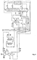
- atmospheric air is drawn in through a filter 2, compressed in an air compressor 3 to a pressure of 5 to 14 bar, preferably 5.5 to 6.5 bar, and then divided into a first partial flow 4 and a second partial flow 5.
- the second partial flow 5 is fed to a combustion chamber 6 and burned there with a fuel 7.
- the exhaust gas 8 from the combustion is expanded in a gas turbine 9 while performing work.
- the first partial stream 4 is freed of the compression heat (aftercooler 10), cooled further in direct heat exchange with water 11, cleaned in a molecular sieve system 12 and fed to the main heat exchanger 14 via line 13.
- the air cooled to approximately dew point is fed via line 15 to the pressure column 17 of a double rectification column 16, preferably directly above the sump.
- the operating pressure of the pressure column 17 is 5 to 14 bar, preferably 5.5 to 6.5 bar.
- gaseous nitrogen is liquefied in the main condenser 19 against evaporating oxygen from the bottom of the low pressure column 18.
- the condensate 20 is fed as return to the pressure column 17 (line 21) or - after subcooling in the counterflow 23 - to the low pressure column 18 (line 22).
- Oxygen-enriched bottom liquid 24 from the pressure column 17 is also supercooled (23) and fed into the low-pressure column 18 (operating pressure 1.3 to 2 bar, preferably 1.5 to 1.7 bar) at an intermediate level.
- Gaseous nitrogen 25 from the top of the low-pressure column can be removed as product after heating in the counterflow 23 and in the main heat exchanger 14 via line 26.
- At least part of the oxygen product generated in the low pressure column 17 is drawn off in liquid form (line 27) and brought to pressure by means of a pump 28, for example to 5 to 110 bar, depending on the product pressure required.
- a pump 28 for example to 5 to 110 bar, depending on the product pressure required.
- the pressure increase can be brought about by static height or by pressure build-up evaporation in a liquid tank.
- the high pressure liquid is evaporated in the main heat exchanger 14 and discharged via line 29 as a gaseous pressure product.
- product evaporation is possible in a condenser evaporator separate from the main heat exchanger (see for example EP-A-0 584 419).
- part 30 of the purified feed air is used specifically as a process stream, which supplies the heat required for the evaporation of the internally compressed liquid product. It is brought to a pressure of 12 to 120 bar, preferably 15 to 60 bar, in a first post-compressor 31 and a second post-compressor 33. The heat of compression is removed in an aftercooler 32, 34, respectively.
- the post-compressed air condenses at least partially, preferably completely, against the evaporating liquid oxygen and is throttled via line 35 into the pressure column 17.
- the feed point is preferably a few theoretical floors above the introduction of the main air (line 15).
- a portion 36 of the post-compressed air is branched off between the two post-compressors 31, 33, fed to a turbine 37 at a temperature lying between the temperatures at the warm and cold ends of the main heat exchanger, and there working from 10 to 60 bar, preferably 12 to 50 bar, to approximately Pressure column pressure relaxed.
- the mechanical energy generated in this way is used for recompression 33.
- the relaxed air 38 is led together with the main air 15 to the pressure column 17.
- the branch leading through turbine 37, the second post-compressor 33 and the after-cooler 34 can be omitted.
- the pressure required for the evaporation of the liquid product must then already be reached in the first (and only) post-compressor 31.
- the exemplary embodiment shown in FIG. 2 differs from FIG. 1 by the use of nitrogen 230 from the pressure column 17 instead of air for the vaporization of the liquid pressurized oxygen.
- the nitrogen gas 230 is first heated to approximately ambient temperature in the main heat exchanger 14 and then brought to a pressure of 12 to 120 bar, preferably 15 to 60 bar, in the first post-compressor 231 and in the second post-compressor 233.
- a portion of the post-compressed nitrogen is at least partially, preferably completely, condensed against the evaporating liquid oxygen in the main heat exchanger 14 and throttled via line 235 into the pressure column 17; another part 236 is expanded in the turbine 237, which drives the second post-compressor 233, to approximately pressure column pressure and is returned to the circuit via line 238.
- gas turbine 9, air compressor 3 and first post-compressor 31/231 are preferably seated on a common shaft.
- a motor or generator can additionally sit on the common shaft.
- the mass transfer elements in the pressure column 17 and low pressure column 18 can consist of conventional still bottoms, packing (disordered packing) and / or orderly pack exist. Combinations of different types of elements in one column are also possible. Because of the low pressure drop, ordered packings in all columns, especially in the low pressure column, are preferred.
Landscapes
- Engineering & Computer Science (AREA)
- Physics & Mathematics (AREA)
- Mechanical Engineering (AREA)
- Thermal Sciences (AREA)
- General Engineering & Computer Science (AREA)
- Health & Medical Sciences (AREA)
- Emergency Medicine (AREA)
- Separation By Low-Temperature Treatments (AREA)
Abstract
Description
- Die Erfindung betrifft ein Verfahren zur Luftzerlegung durch Tieftemperaturrektifikation in einem Rektifiziersäulensystem, das mindestens eine Rektifiziersäule aufweist, mit den im Patentanspruch 1 aufgeführten Schritten (a) bis (h).
- Derartige Verfahren integrieren die destillative Luftzerlegung und einen Prozeß, in der Druckluft und gegebenenfalls Luftgase verbraucht werden, indem die Einsatzluft für den Luftzerleger und die in dem chemischen Prozeß benötigte Luft gemeinsam verdichtet werden. Die durch arbeitsleistende Entspannung von Abgasen aus der chemischen Reaktion erzeugte mechanische Energie wird häufig zur Gewinnung elektrischer Energie eingesetzt. Gegebenenfalls kann mechanische Energie auch unmittelbar zur Luftverdichtung verwendet werden. Bei der chemischen Reaktion kann es sich beispielsweise um eine Kohlevergasung oder um eine Verbrennung handeln.
- Bei dem Verfahren wird eines der Produkte flüssig aus der Rektifikation entnommen, im flüssigen Zustand auf Druck gebracht und anschließend gegen einen entsprechend verdichteten Prozeßstrom verdampft, wobei letzterer mindestens teilweise kondensiert. Mit Hilfe dieser Innenverdichtung ist es möglich, ein gasförmiges Produkt, wie es häufig für einen chemischen Prozeß benötigt wird, mit relativ geringem apparativem Aufwand herzustellen.
- Ein Verfahren der eingangs genannten Art ist aus der EP-A-0 584 419 bekannt. Hier wird ein Teil der verdichteten Luft einer Brennkammer zugeführt, der Rest dient als Einsatzluft für die Luftzerlegung. Flüssigsauerstoff wird aus der Niederdruckstufe einer Doppelrektifiziersäule entnommen, mit Hilfe einer Pumpe auf Druck gebracht und gegen nachverdichtete Luft verdampft.
- Der Erfindung liegt die Aufgabe zugrunde, ein derartiges Verfahren und eine entsprechende Vorrichtung so auszugestalten, daß der Prozeß energetisch besonders günstig gefahren werden kann.
- Diese Aufgabe wird dadurch gelöst, daß mindestens ein Teil der mechanischen Energie, die bei der arbeitsleistenden Entspannung des Abgases der chemischen Reaktion erzeugt wird, zur Nachverdichtung des Prozeßstroms verwendet wird, der zur Verdampfung des Flüssigproduktstroms durch indirekten Wärmeaustausch dient.
- Es braucht damit keine externe Energie für die Nachverdichtung des Prozeßstroms eingesetzt zu werden. Durch einfache mechanische Kopplung der Entspannungsmaschine für Abgas (in der Regel einer Gasturbine) mit einem Kompressor zur Nachverdichtung über eine gemeinsame Welle kann die bei der Entspannung geleistete Arbeit auf den Verdichter übertragen werden. Möglicherweise überschüssige mechanische Energie kann beispielsweise von einem Bremsgebläse aufgenommen werden, günstiger ist jedoch die Umwandlung in elektrische Energie durch Ankopplung eines Generators an die gemeinsame Welle.
- Zusätzlich kann ein Teil der mechanischen Energie, die bei der arbeitsleistenden Entspannung des Abgases der chemischen Reaktion erzeugt wird, auf andere Verdichter übertragen, insbesondere zur gemeinsamen Verdichtung des Luftstroms verwendet werden. Ein Generator/Elektromotor dient zum Ausgleich eines eventuellen Überschusses/Defizits an mechanischer Energie zum Antrieb der zwei oder mehr Verdichter.
- Der Prozeßstrom zur Verdampfung des Flüssigprodukts kann durch einen Teil des ersten Teilstroms der verdichteten Luft oder durch einen Stickstoff-Produktstrom aus der oder einer der Rektifiziersäulen gebildet werden. Im ersten Fall wird vorzugsweise ein Teil der auf mindestens Rektifizierdruck verdichteten Einsatzluft nachverdichtet, gegen das verdampfende Flüssigprodukt teilweise oder vollständig kondensiert und anschließend in die oder eine der Rektifiziersäulen eingespeist. Im zweiten Fall wird gasförmiger Stickstoff beispielsweise aus der Drucksäule einer Doppelrektifiziersäule entnommen, nachverdichtet, mindestens teilweise kondensiert und als Rücklauf auf eine der Rektifiziersäulen aufgegeben und/oder als Flüssigprodukt abgezogen.
- Es ist ferner günstig, wenn ein Teil des nachverdichteten Prozeßstroms, der nicht in indirekten Wärmeaustausch mit dem verdampfenden Flüssigproduktstrom gebracht wird, arbeitsleistend entspannt wird. Damit können die Verdampfung des innenverdichteten Produkts und ein Kältekreislauf, der beispielsweise mit Luft oder Stickstoff betrieben wird, integriert werden.
- Im Kältekreislauf erzeugte Arbeit kann zur Nachverdichtung des Prozeßstroms verwendet werden, beispielsweise über einen zweiten Verdichter, der mechanisch mit der Entspannungsmaschine für den Prozeßstrom gekoppelt ist. Dieser zweite Verdichter kann dem mit der Gasturbine gekoppelten Kompressor vor- oder nachgeschaltet sein.
- Wenn das Rektifiziersäulensystem eine aus Drucksäule und Niederdrucksäule bestehende Doppelsäule aufweist, kann der Flüssigproduktstrom aus dem unteren Bereich der Niederdrucksäule entnommen werden, so daß gasförmiger Sauerstoff als innenverdichtetes Druckprodukt gewonnen wird. Alternativ oder zusätzlich können Stickstoff (beispielsweise vom Kopf der Drucksäule) oder Argon aus einer angeschlossenen Argonrektifikation flüssig auf Druck gebracht und gegen den nachverdichteten Prozeßstrom verdampft werden. Selbstverständlich ist es möglich, das oder die Flüssigprodukte vor oder nach der Innenverdichtung in einem Flüssigtank zwischenzuspeichern.
- Die Erfindung betrifft außerdem eine Vorrichtung zur Luftzerlegung durch Tieftemperaturrektifikation gemäß Patentanspruch 8.
- Die Erfindung sowie weitere Einzelheiten der Erfindung werden im folgenden anhand von in den Zeichnungen dargestellten Ausführungsbeispielen näher erläutert. Hierbei zeigen:
- Figur 1
- ein besonders bevorzugtes Ausführungsbeispiel für das erfindungsgemäße Verfahren und die erfindungsgemäße Vorrichtung, bei dem der nachverdichtete Prozeßstrom durch einen Teil der verdichteten Einsatzluft gebildet wird, und
- Figur 2
- ein weiteres Ausführungbeispiel mit Stickstoff als nachverdichtetem Prozeßstrom.
- Zunächst werden anhand von Figur 1 diejenigen Vefahrensschritte und Apparateteile beschrieben, die beiden Ausführungsbeispielen gemeinsam sind.
- Atmosphärische Luft wird bei 1 durch ein Filter 2 angesaugt, in einem Luftverdichter 3 auf einen Druck von 5 bis 14 bar, vorzugsweise 5,5 bis 6,5 bar komprimiert und anschließend in einen ersten Teilstrom 4 und einen zweiten Teilstrom 5 geteilt. Der zweite Teilstrom 5 wird einer Brennkammer 6 zugeführt und dort mit einem Brennstoff 7 verbrannt. Das Abgas 8 aus der Verbrennung wird in einer Gasturbine 9 arbeitsleistend entspannt.
- Der erste Teilstrom 4 wird von der Kompressionswärme befreit (Nachkühler 10), in direktem Wärmeaustausch mit Wasser 11 weiter abgekühlt, in einer Molsiebanlage 12 gereinigt und über Leitung 13 dem Hauptwärmetauscher 14 zugeleitet. Die auf etwa Taupunkt abgekühlte Luft wird über Leitung 15 der Drucksäule 17 einer Doppelrektifiziersäule 16 zugeleitet, vorzugsweise direkt oberhalb des Sumpfes. Der Betriebsdruck der Drucksäule 17 beträgt 5 bis 14 bar, vorzugsweise 5,5 bis 6,5 bar. Am Kopf der Drucksäule 17 anfallender gasförmiger Stickstoff wird im Hauptkondensator 19 gegen verdampfenden Sauerstoff aus dem Sumpf der Niederdrucksäule 18 verflüssigt. Das Kondensat 20 wird als Rücklauf auf die Drucksäule 17 (Leitung 21) beziehungsweise - nach Unterkühlung im Gegenströmer 23 - auf die Niederdrucksäule 18 aufgegeben (Leitung 22). Sauerstoffangereicherte Sumpfflüssigkeit 24 aus der Drucksäule 17 wird ebenfalls unterkühlt (23) und auf einem Zwischenniveau in die Niederdrucksäule 18 (Betriebsdruck 1,3 bis 2 bar, vorzugsweise 1,5 bis 1,7 bar) eingespeist. Gasförmiger Stickstoff 25 vom Kopf der Niederdrucksäule kann nach Anwärmung im Gegenströmer 23 und im Hauptwärmetauscher 14 über Leitung 26 als Produkt abgezogen werden.
- Mindestens ein Teil des in der Niederdrucksäule 17 erzeugten Sauerstoffprodukts wird flüssig abgezogen (Leitung 27) und mittels einer Pumpe 28 auf Druck gebracht, beispielsweise auf 5 bis 110 bar, je nach benötigtem Produktdruck. Alternativ oder zusätzlich kann die Druckerhöhung durch statische Höhe oder durch Druckaufbauverdampfung in einem Flüssigtank bewirkt werden. Die Hochdruckflüssigkeit wird im Hauptwärmetauscher 14 verdampft und über Leitung 29 als gasförmiges Druckprodukt abgeführt. Alternativ ist die Produktverdampfung in einem vom Hauptwärmetauscher getrennten Kondensator-Verdampfter möglich (siehe beispielweise EP-A-0 584 419).
- Im Beispiel der Figur 1 wird speziell ein Teil 30 der gereinigten Einsatzluft als Prozeßstrom eingesetzt, der die für die Verdampfung des innenverdichteten Flüssigprodukts benötigte Wärme liefert. Er wird in einem ersten Nachverdichter 31 und einem zweiten Nachverdichter 33 auf einen Druck von 12 bis 120 bar, vorzugsweise 15 bis 60 bar gebracht. Die Kompressionswärme wird jeweils in einem Nachkühler 32, 34 entfernt. Im Hauptwärmetauscher 14 kondensiert die nachverdichtete Luft mindestens teilweise, vorzugsweise vollständig gegen den verdampfenden Flüssigsauerstoff und wird über Leitung 35 in die Drucksäule 17 eingedrosselt. Die Einspeisestelle liegt vorzugsweise einige theoretische Böden oberhalb der Einführung der Hauptluft (Leitung 15).
- Ein Teil 36 der nachverdichteten Luft wird zwischen den beiden Nachverdichtern 31, 33 abgezweigt, bei einer zwischen den Temperaturen am warmen und kalten Ende des Hauptwärmetauschers liegenden Temperatur einer Turbine 37 zugeführt und dort arbeitsleistend von 10 bis 60 bar, vorzugsweise 12 bis 50 bar auf etwa Drucksäulendruck entspannt. Die dabei erzeugte mechanische Energie wird zur Nachverdichtung 33 eingesetzt. Die entspannte Luft 38 wird gemeinsam mit der Hauptluft 15 zur Drucksäule 17 geführt.
- Falls die in Turbine 37 gewonnene Kälte nicht benötigt wird, können der durch Turbine 37 führende Ast, der zweite Nachverdichter 33 und der Nachkühler 34 weggelassen werden. Der für die Verdampfung des Flüssigprodukts benötigte Druck muß dann bereits im ersten (und einzigen) Nachverdichter 31 erreicht werden.
- Das in Figur 2 dargestellte Ausführungsbeispiel unterscheidet sich von Figur 1 durch die Verwendung von Stickstoff 230 aus der Drucksäule 17 anstelle von Luft für die Verdampfung des flüssigen Drucksauerstoffs. Das Stickstoffgas 230 wird zunächst im Hauptwärmetauscher 14 auf etwa Umgebungstemperatur angewärmt und anschließend im ersten Nachverdichter 231 und im zweiten Nachverdichter 233 auf einen Druck von von 12 bis 120 bar, vorzugsweise 15 bis 60 bar gebracht. Ein Teil des nachverdichteten Stickstoffs wird im Hauptwärmetauscher 14 gegen den verdampfenden Flüssigsauerstoff mindestens teilweise, vorzugsweise vollständig kondensiert und über Leitung 235 in die Drucksäule 17 eingedrosselt; ein anderer Teil 236 wird in der Turbine 237, die den zweiten Nachverdichter 233 antreibt, auf etwa Drucksäulendruck entspannt und über Leitung 238 in den Kreislauf zurückgeführt. Ebenso wie beim ersten Ausführungsbeispiel ist es bei niedrigem oder anderweitig gedecktem Kältebedarf möglich, auf die Turbinen-Nachverdichter-Kombination 237/233 zu verzichten.
- Bei beiden Ausführungsbeispielen sitzen Gasturbine 9, Luftverdichter 3 und erster Nachverdichter 31/231 vorzugsweise auf einer gemeinsamen Welle. Je nachdem, ob die in der Gasturbine erzeugte mechanische Energie (unter Berücksichtigung des Wirkungsgrads der Maschinen) geringer oder größer als die von den angetriebenen Verdichtern 3, 31/231 benötigte Leistung ist, kann zusätzlich ein Motor oder Generator auf der gemeinsamen Welle sitzen.
- Die Stoffaustauschelemente in Drucksäule 17 und Niederdrucksäule 18 können aus konventionellen Destillierböden, Füllkörpern (ungeordneter Packung) und/oder geordneter Packung bestehen. Auch Kombinationen verschiedenartiger Elemente in einer Säule sind möglich. Wegen des geringen Druckverlusts werden geordnete Packungen in allen Säulen, insbesondere in der Niederdrucksäule, bevorzugt.
Claims (8)
- Verfahren zur Luftzerlegung durch Tieftemperaturrektifikation in einem Rektifiziersäulensystem (16), das mindestens eine Rektifiziersäule (17,18) aufweist, mit folgenden Schritten:(a) Verdichtung (3) eines Luftstroms (1) auf mindestens den höchsten Druck, der innerhalb des Rektifiziersäulensystems (16) herrscht,(b) Aufteilung des verdichteten Luftstroms in einen ersten Teilstrom (4), der als Einsatzluftstrom für das Rektifiziersäulensystem dient, und in einen zweiten Teilstrom (5), der einer chemischen Reaktion (6) als Oxidationsmittel zugeführt wird,(c) arbeitsleistende Entspannung (9) mindestens eines Teils des Abgases (8) der chemischen Reaktion (7),(d) Abkühlung (14) des ersten Teilstroms (4) auf etwa Taupunktstemperatur und Einführung (15) in die beziehungsweise eine der Rektifiziersäulen (17),(e) Entnahme eines Flüssigproduktstroms (27) aus der beziehungsweise einer der Rektifiziersäulen (18),(f) Erhöhung (28) des Drucks im Flüssigproduktstrom (27),(g) Nachverdichtung (31, 33; 231, 233) eines Prozeßstroms (30; 230) der Tieftemperaturrektifikation auf einen Druck, der wesentlich über dem höchsten im Rektifiziersäulensystem (16) vorkommenden Druck liegt, und(h) Verdampfung des Flüssigproduktstroms durch indirekten Wärmeaustausch (14) mit mindestens einem Teil (35, 235) des nachverdichteten Prozeßstroms,dadurch gekennzeichnet, daß(i) mindestens ein Teil der mechanischen Energie, die bei der arbeitsleistenden Entspannung (9) des Abgases (8) der chemischen Reaktion (7) in Schritt (c) erzeugt wird, zur Nachverdichtung (31) des Prozeßstroms (30; 230) in Schritt (g) verwendet wird.
- Verfahren nach Anspruch 1, dadurch gekennzeichnet, daß ein Teil der mechanischen Energie, die bei der arbeitsleistenden Entspannung (9) des Abgases (8) der chemischen Reaktion (7) in Schritt (c) erzeugt wird, zur Verdichtung (9) des Luftstroms (1) in Schritt (a) verwendet wird.
- Verfahren nach Anspruch 1 oder 2, dadurch gekennzeichnet, daß der Prozeßstrom durch einen Teil (30) des ersten Teilstroms (4) der verdichteten Luft gebildet wird.
- Verfahren nach Anspruch 1 oder 2, dadurch gekennzeichnet, daß der Prozeßstrom durch einen Stickstoff-Produktstrom (230) aus der oder einer der Rektifiziersäulen (17) gebildet wird.
- Verfahren nach einem der Ansprüche 1 bis 4, dadurch gekennzeichnet, daß ein Teil (36; 236) des nachverdichteten Prozeßstroms, der nicht in indirekten Wärmeaustausch mit dem verdampfenden Flüssigproduktstrom (27) gebracht wird, arbeitsleistend entspannt (37; 237) wird.
- Verfahren nach Anspruch 5, dadurch gekennzeichnet, daß mindestens ein Teil der mechanischen Energie, die bei der arbeitsleistenden Entspannung (37; 237) des Teils (36; 236) des Prozeßstroms erzeugt wird, zur Nachverdichtung (33) des Prozeßstroms verwendet wird.
- Verfahren nach einem der Ansprüche 1 bis 6, dadurch gekennzeichnet, daß das Rektifiziersäulensystem eine Drucksäule (17) und eine Niederdrucksäule (18) aufweist, wobei der Flüssigproduktstrom (27) aus dem unteren Bereich der Niederdrucksäule (18) entnommen wird.
- Vorrichtung zur Luftzerlegung durch Tieftemperaturrektifikation mit einem Rektifiziersäulensystem (16), das mindestens eine Rektifiziersäule (17,18) aufweist, sowie(a) einen Luftverdichter (3),(b) eine erste Luftleitung (4), die vom Austritt des Luftverdichters (3) durch einen Hauptwärmetauscher (14) zum Rektifiziersäulensystem (16) führt,(c) eine zweite Luftleitung (5), die vom Austritt des Luftverdichters (3) zu einer chemischen Reaktionsvorrichtung (6) führt,(d) eine Gasturbine (9), deren Eintritt mit dem Austritt der chemischen Reaktionsvorrichtung (6) verbunden ist,(e) eine Flüssigproduktleitung (27) zur Entnahme eines Flüssigproduktstroms aus der beziehungsweise einer der Rektifiziersäulen (18),(f) ein Mittel (28) zur Erhöhung des Drucks im Flüssigproduktstrom,(g) Mittel (33, 31; 231; 233) zur Nachverdichtung eines Prozeßstroms (30; 230) der Tieftemperaturrektifikation auf einen Druck, der wesentlich über dem höchsten im Rektifiziersäulensystem (16) vorkommenden Druck liegt, und(h) Mittel (14) zur Verdampfung des Flüssigproduktstroms durch indirekten Wärmeaustausch mit mindestens einem Teil des nachverdichteten Prozeßstroms,gekennzeichnet durch(i) Mittel zur Übertragung mindestens eines Teils der in der Gasturbine (9) erzeugten mechanischen Energie auf die Mittel (31; 231) zur Nachverdichtung des Prozeßstroms.
Applications Claiming Priority (2)
| Application Number | Priority Date | Filing Date | Title |
|---|---|---|---|
| DE19529681 | 1995-08-11 | ||
| DE19529681A DE19529681C2 (de) | 1995-08-11 | 1995-08-11 | Verfahren und Vorrichtung zur Luftzerlegung durch Tieftemperaturrektifikation |
Publications (3)
| Publication Number | Publication Date |
|---|---|
| EP0758733A2 true EP0758733A2 (de) | 1997-02-19 |
| EP0758733A3 EP0758733A3 (de) | 1997-07-30 |
| EP0758733B1 EP0758733B1 (de) | 2000-11-02 |
Family
ID=7769333
Family Applications (1)
| Application Number | Title | Priority Date | Filing Date |
|---|---|---|---|
| EP96112620A Expired - Lifetime EP0758733B1 (de) | 1995-08-11 | 1996-08-05 | Verfahren und Vorrichtung zur Luftzerlegung durch Tieftemperaturrektifikation |
Country Status (4)
| Country | Link |
|---|---|
| US (1) | US5845517A (de) |
| EP (1) | EP0758733B1 (de) |
| DE (2) | DE19529681C2 (de) |
| DK (1) | DK0758733T3 (de) |
Families Citing this family (33)
| Publication number | Priority date | Publication date | Assignee | Title |
|---|---|---|---|---|
| GB9717349D0 (en) * | 1997-08-15 | 1997-10-22 | Boc Group Plc | Air separation plant |
| US6178775B1 (en) * | 1998-10-30 | 2001-01-30 | The Boc Group, Inc. | Method and apparatus for separating air to produce an oxygen product |
| US6263659B1 (en) | 1999-06-04 | 2001-07-24 | Air Products And Chemicals, Inc. | Air separation process integrated with gas turbine combustion engine driver |
| US6256994B1 (en) | 1999-06-04 | 2001-07-10 | Air Products And Chemicals, Inc. | Operation of an air separation process with a combustion engine for the production of atmospheric gas products and electric power |
| US6345493B1 (en) | 1999-06-04 | 2002-02-12 | Air Products And Chemicals, Inc. | Air separation process and system with gas turbine drivers |
| DE102007031765A1 (de) | 2007-07-07 | 2009-01-08 | Linde Ag | Verfahren zur Tieftemperaturzerlegung von Luft |
| DE102007031759A1 (de) | 2007-07-07 | 2009-01-08 | Linde Ag | Verfahren und Vorrichtung zur Erzeugung von gasförmigem Druckprodukt durch Tieftemperaturzerlegung von Luft |
| US20100192629A1 (en) * | 2009-01-30 | 2010-08-05 | Richard John Jibb | Oxygen product production method |
| US8726691B2 (en) * | 2009-01-30 | 2014-05-20 | Praxair Technology, Inc. | Air separation apparatus and method |
| US20100192628A1 (en) * | 2009-01-30 | 2010-08-05 | Richard John Jibb | Apparatus and air separation plant |
| DE102009034979A1 (de) | 2009-04-28 | 2010-11-04 | Linde Aktiengesellschaft | Verfahren und Vorrichtung zur Erzeugung von gasförmigem Drucksauerstoff |
| EP2312248A1 (de) | 2009-10-07 | 2011-04-20 | Linde Aktiengesellschaft | Verfahren und Vorrichtung Gewinnung von Drucksauerstoff und Krypton/Xenon |
| DE102010052544A1 (de) | 2010-11-25 | 2012-05-31 | Linde Ag | Verfahren zur Gewinnung eines gasförmigen Druckprodukts durch Tieftemperaturzerlegung von Luft |
| DE102010052545A1 (de) | 2010-11-25 | 2012-05-31 | Linde Aktiengesellschaft | Verfahren und Vorrichtung zur Gewinnung eines gasförmigen Druckprodukts durch Tieftemperaturzerlegung von Luft |
| EP2520886A1 (de) | 2011-05-05 | 2012-11-07 | Linde AG | Verfahren und Vorrichtung zur Erzeugung eines gasförmigen Sauerstoff-Druckprodukts durch Tieftemperaturzerlegung von Luft |
| DE102011112909A1 (de) | 2011-09-08 | 2013-03-14 | Linde Aktiengesellschaft | Verfahren und Vorrichtung zur Gewinnung von Stahl |
| EP2600090B1 (de) | 2011-12-01 | 2014-07-16 | Linde Aktiengesellschaft | Verfahren und Vorrichtung zur Erzeugung von Drucksauerstoff durch Tieftemperaturzerlegung von Luft |
| DE102011121314A1 (de) | 2011-12-16 | 2013-06-20 | Linde Aktiengesellschaft | Verfahren zur Erzeugung eines gasförmigen Sauerstoff-Druckprodukts durch Tieftemperaturzerlegung von Luft |
| DE102012006484A1 (de) * | 2012-03-29 | 2013-10-02 | Linde Aktiengesellschaft | Transportables Paket mit einer Coldbox und Verfahren zum Herstellen einer Tieftemperatur-Luftzerlegungsanlage |
| DE102012017488A1 (de) | 2012-09-04 | 2014-03-06 | Linde Aktiengesellschaft | Verfahren zur Erstellung einer Luftzerlegungsanlage, Luftzerlegungsanlage und zugehöriges Betriebsverfahren |
| WO2014154339A2 (de) | 2013-03-26 | 2014-10-02 | Linde Aktiengesellschaft | Verfahren zur luftzerlegung und luftzerlegungsanlage |
| EP2784420A1 (de) | 2013-03-26 | 2014-10-01 | Linde Aktiengesellschaft | Verfahren zur Luftzerlegung und Luftzerlegungsanlage |
| EP2801777A1 (de) | 2013-05-08 | 2014-11-12 | Linde Aktiengesellschaft | Luftzerlegungsanlage mit Hauptverdichterantrieb |
| EP3044522A2 (de) * | 2013-09-10 | 2016-07-20 | L'Air Liquide Société Anonyme pour l'Etude et l'Exploitation des Procédés Georges Claude | Verfahren und vorrichtung zur trennung bei temperaturen unter der umgebungstemperatur |
| DE102013017590A1 (de) | 2013-10-22 | 2014-01-02 | Linde Aktiengesellschaft | Verfahren zur Gewinnung eines Krypton und Xenon enthaltenden Fluids und hierfür eingerichtete Luftzerlegungsanlage |
| EP2963371B1 (de) | 2014-07-05 | 2018-05-02 | Linde Aktiengesellschaft | Verfahren und vorrichtung zur gewinnung eines druckgasprodukts durch tieftemperaturzerlegung von luft |
| PL2963369T3 (pl) | 2014-07-05 | 2018-10-31 | Linde Aktiengesellschaft | Sposób i urządzenie do niskotemperaturowej separacji powietrza |
| EP2963370B1 (de) | 2014-07-05 | 2018-06-13 | Linde Aktiengesellschaft | Verfahren und vorrichtung zur tieftemperaturzerlegung von luft |
| EP2963367A1 (de) | 2014-07-05 | 2016-01-06 | Linde Aktiengesellschaft | Verfahren und Vorrichtung zur Tieftemperaturzerlegung von Luft mit variablem Energieverbrauch |
| US10668859B2 (en) * | 2017-02-24 | 2020-06-02 | Velvac Incorporated | Method and apparatus for communicating video signals and data between a trailer and a towing vehicle |
| US10684071B2 (en) * | 2017-08-25 | 2020-06-16 | Praxair Technology, Inc. | Annular divided wall column for an air separation unit |
| US10578357B2 (en) * | 2017-08-25 | 2020-03-03 | Praxair Technology, Inc. | Annular divided wall column with ring shaped collectors and distributers for an air separation unit |
| US11566841B2 (en) * | 2019-11-27 | 2023-01-31 | L'air Liquide, Societe Anonyme Pour L'etude Et L'exploitation Des Procedes Georges Claude | Cryogenic liquefier by integration with power plant |
Family Cites Families (8)
| Publication number | Priority date | Publication date | Assignee | Title |
|---|---|---|---|---|
| US3731495A (en) * | 1970-12-28 | 1973-05-08 | Union Carbide Corp | Process of and apparatus for air separation with nitrogen quenched power turbine |
| IL36741A (en) * | 1971-04-30 | 1974-11-29 | Zakon T | Method for the separation of gaseous mixtures with recuperation of mechanical energy and apparatus for carrying out this method |
| US4224045A (en) * | 1978-08-23 | 1980-09-23 | Union Carbide Corporation | Cryogenic system for producing low-purity oxygen |
| EP0093448B1 (de) * | 1982-05-03 | 1986-10-15 | Linde Aktiengesellschaft | Verfahren und Vorrichtung zur Gewinnung von gasförmigem Sauerstoff unter erhöhtem Druck |
| JP2685483B2 (ja) * | 1988-04-11 | 1997-12-03 | 株式会社日立製作所 | 空気分離装置 |
| EP0383994A3 (de) * | 1989-02-23 | 1990-11-07 | Linde Aktiengesellschaft | Verfahren und Vorrichtung zur Luftzerlegung durch Rektifikation |
| US5251451A (en) * | 1992-08-28 | 1993-10-12 | Air Products And Chemicals, Inc. | Multiple reboiler, double column, air boosted, elevated pressure air separation cycle and its integration with gas turbines |
| FR2704632B1 (fr) * | 1993-04-29 | 1995-06-23 | Air Liquide | Procede et installation pour la separation de l'air. |
-
1995
- 1995-08-11 DE DE19529681A patent/DE19529681C2/de not_active Expired - Fee Related
-
1996
- 1996-08-05 DK DK96112620T patent/DK0758733T3/da active
- 1996-08-05 EP EP96112620A patent/EP0758733B1/de not_active Expired - Lifetime
- 1996-08-05 DE DE59606078T patent/DE59606078D1/de not_active Expired - Fee Related
- 1996-08-12 US US08/695,601 patent/US5845517A/en not_active Expired - Fee Related
Also Published As
| Publication number | Publication date |
|---|---|
| US5845517A (en) | 1998-12-08 |
| EP0758733B1 (de) | 2000-11-02 |
| DK0758733T3 (da) | 2001-01-15 |
| EP0758733A3 (de) | 1997-07-30 |
| DE19529681A1 (de) | 1997-02-13 |
| DE19529681C2 (de) | 1997-05-28 |
| DE59606078D1 (de) | 2000-12-07 |
Similar Documents
| Publication | Publication Date | Title |
|---|---|---|
| DE19529681C2 (de) | Verfahren und Vorrichtung zur Luftzerlegung durch Tieftemperaturrektifikation | |
| EP0505812B1 (de) | Verfahren zur Tieftemperaturzerlegung von Luft | |
| DE69509841T2 (de) | Verfahren und Vorrichtung zur Herstellung von Sauerstoff | |
| EP0955509B1 (de) | Verfahren und Vorrichtung zur Gewinnung von hochreinem Sauerstoff | |
| EP0949471B1 (de) | Luftzerlegungsanlage mit zwei verschiedenen Betriebsmodi | |
| DE69413918T2 (de) | Tieftemperaturzerlegung von Luft | |
| EP1067345B1 (de) | Verfahren und Vorrichtung zur Tieftemperaturzerlegung von Luft | |
| DE69205424T2 (de) | Verfahren und Vorrichtung für die Luftzerlegung durch Rektifikation. | |
| EP0384483A2 (de) | Verfahren und Vorrichtung zur Luftzerlegung durch Rektifikation | |
| DE19803437A1 (de) | Verfahren und Vorrichtung zur Gewinnung eines Druckprodukts durch Tieftemperaturzerlegung von Luft | |
| EP3290843A2 (de) | Verfahren und vorrichtung zur erzeugung von druckstickstoff und flüssigstickstoff durch tieftemperaturzerlegung von luft | |
| EP1074805B1 (de) | Verfahren und Vorrichtung zur Gewinnung von Sauerstoff unter überatmosphärischem Druck | |
| EP2867599A2 (de) | Verfahren und vorrichtung zur erzeugung elektrischer energie | |
| DE69614950T2 (de) | Verfahren und vorrichtung zur erzeugung von hochreinem stickstoff | |
| EP1146301A1 (de) | Verfahren und Vorrichtung zur Gewinnung von Drückstickstoff durch Tieftemperaturzerlegung von Luft | |
| EP1213552A1 (de) | Maschinensystem zur arbeitsleistenden Entspannung zweier Prozess-Ströme | |
| EP0768503B1 (de) | Dreifachsäulenverfahren zur Tieftemperaturzerlegung von Luft | |
| EP1199532B1 (de) | Drei-Säulen-System zur Tieftemperatur-Zerlegung von Luft | |
| DE10045128A1 (de) | Verfahren und Vorrichtung zur Erzeugung hoch reinen Stickstoffs durch Tieftemperatur-Luftzerlegung | |
| EP0775881B1 (de) | Verfahren und Vorrichtung zur Gewinnung von Sauerstoff und Stickstoff unter überatmosphärischem Druck | |
| EP1209431B1 (de) | Verfahren und Vorrichtung zur Erzeugung von Sauerstoff und Stickstoff | |
| EP1189002A1 (de) | Verfahren und Vorrichtung zur Gewinnung eines gasförmigen Produkts durch Tieftemperaturzerlegung von Luft | |
| DE10013074A1 (de) | Verfahren zur Gewinnung von gasförmigem Stickstoff | |
| EP1284403B1 (de) | Verfahren und Vorrichtung zur Erzeugung von Sauerstoff durch Tieftemperatur-Zerlegung von Luft | |
| DE19819338A1 (de) | Verfahren und Vorrichtung zur Gewinnung von hochreinem Druckstickstoff |
Legal Events
| Date | Code | Title | Description |
|---|---|---|---|
| PUAI | Public reference made under article 153(3) epc to a published international application that has entered the european phase |
Free format text: ORIGINAL CODE: 0009012 |
|
| AK | Designated contracting states |
Kind code of ref document: A2 Designated state(s): DE DK FR GB NL |
|
| PUAL | Search report despatched |
Free format text: ORIGINAL CODE: 0009013 |
|
| AK | Designated contracting states |
Kind code of ref document: A3 Designated state(s): DE DK FR GB NL |
|
| 17P | Request for examination filed |
Effective date: 19970729 |
|
| 17Q | First examination report despatched |
Effective date: 19990527 |
|
| GRAG | Despatch of communication of intention to grant |
Free format text: ORIGINAL CODE: EPIDOS AGRA |
|
| GRAG | Despatch of communication of intention to grant |
Free format text: ORIGINAL CODE: EPIDOS AGRA |
|
| GRAH | Despatch of communication of intention to grant a patent |
Free format text: ORIGINAL CODE: EPIDOS IGRA |
|
| GRAH | Despatch of communication of intention to grant a patent |
Free format text: ORIGINAL CODE: EPIDOS IGRA |
|
| GRAA | (expected) grant |
Free format text: ORIGINAL CODE: 0009210 |
|
| AK | Designated contracting states |
Kind code of ref document: B1 Designated state(s): DE DK FR GB NL |
|
| ET | Fr: translation filed | ||
| REF | Corresponds to: |
Ref document number: 59606078 Country of ref document: DE Date of ref document: 20001207 |
|
| GBT | Gb: translation of ep patent filed (gb section 77(6)(a)/1977) |
Effective date: 20001130 |
|
| REG | Reference to a national code |
Ref country code: DK Ref legal event code: T3 |
|
| PLBQ | Unpublished change to opponent data |
Free format text: ORIGINAL CODE: EPIDOS OPPO |
|
| PLBI | Opposition filed |
Free format text: ORIGINAL CODE: 0009260 |
|
| PLBF | Reply of patent proprietor to notice(s) of opposition |
Free format text: ORIGINAL CODE: EPIDOS OBSO |
|
| 26 | Opposition filed |
Opponent name: L'AIR LIQUIDE, SOCIETE ANONYME POUR L'ETUDE ET L'E Effective date: 20010802 |
|
| NLR1 | Nl: opposition has been filed with the epo |
Opponent name: L'AIR LIQUIDE, SOCIETE ANONYME POUR L'ETUDE ET L'E |
|
| REG | Reference to a national code |
Ref country code: GB Ref legal event code: IF02 |
|
| PLBF | Reply of patent proprietor to notice(s) of opposition |
Free format text: ORIGINAL CODE: EPIDOS OBSO |
|
| PLBF | Reply of patent proprietor to notice(s) of opposition |
Free format text: ORIGINAL CODE: EPIDOS OBSO |
|
| PLBO | Opposition rejected |
Free format text: ORIGINAL CODE: EPIDOS REJO |
|
| PLBN | Opposition rejected |
Free format text: ORIGINAL CODE: 0009273 |
|
| STAA | Information on the status of an ep patent application or granted ep patent |
Free format text: STATUS: OPPOSITION REJECTED |
|
| 27O | Opposition rejected |
Effective date: 20030206 |
|
| NLR2 | Nl: decision of opposition |
Effective date: 20030206 |
|
| REG | Reference to a national code |
Ref country code: FR Ref legal event code: CA |
|
| PGFP | Annual fee paid to national office [announced via postgrant information from national office to epo] |
Ref country code: NL Payment date: 20080803 Year of fee payment: 13 Ref country code: DK Payment date: 20080815 Year of fee payment: 13 Ref country code: DE Payment date: 20080821 Year of fee payment: 13 |
|
| PGFP | Annual fee paid to national office [announced via postgrant information from national office to epo] |
Ref country code: FR Payment date: 20080818 Year of fee payment: 13 |
|
| PGFP | Annual fee paid to national office [announced via postgrant information from national office to epo] |
Ref country code: GB Payment date: 20080813 Year of fee payment: 13 |
|
| REG | Reference to a national code |
Ref country code: NL Ref legal event code: V1 Effective date: 20100301 |
|
| REG | Reference to a national code |
Ref country code: DK Ref legal event code: EBP |
|
| GBPC | Gb: european patent ceased through non-payment of renewal fee |
Effective date: 20090805 |
|
| REG | Reference to a national code |
Ref country code: FR Ref legal event code: ST Effective date: 20100430 |
|
| PG25 | Lapsed in a contracting state [announced via postgrant information from national office to epo] |
Ref country code: NL Free format text: LAPSE BECAUSE OF NON-PAYMENT OF DUE FEES Effective date: 20100301 Ref country code: FR Free format text: LAPSE BECAUSE OF NON-PAYMENT OF DUE FEES Effective date: 20090831 Ref country code: DK Free format text: LAPSE BECAUSE OF NON-PAYMENT OF DUE FEES Effective date: 20090831 Ref country code: DE Free format text: LAPSE BECAUSE OF NON-PAYMENT OF DUE FEES Effective date: 20100302 |
|
| PG25 | Lapsed in a contracting state [announced via postgrant information from national office to epo] |
Ref country code: GB Free format text: LAPSE BECAUSE OF NON-PAYMENT OF DUE FEES Effective date: 20090805 |