EP0759199B1 - Druckfühlende hinweisanordnung - Google Patents
Druckfühlende hinweisanordnung Download PDFInfo
- Publication number
- EP0759199B1 EP0759199B1 EP95905992A EP95905992A EP0759199B1 EP 0759199 B1 EP0759199 B1 EP 0759199B1 EP 95905992 A EP95905992 A EP 95905992A EP 95905992 A EP95905992 A EP 95905992A EP 0759199 B1 EP0759199 B1 EP 0759199B1
- Authority
- EP
- European Patent Office
- Prior art keywords
- force
- pointing device
- transfer member
- sensor
- analog stick
- Prior art date
- Legal status (The legal status is an assumption and is not a legal conclusion. Google has not performed a legal analysis and makes no representation as to the accuracy of the status listed.)
- Expired - Lifetime
Links
- 239000000853 adhesive Substances 0.000 claims description 20
- 230000001070 adhesive effect Effects 0.000 claims description 20
- 238000004382 potting Methods 0.000 claims description 8
- 238000000034 method Methods 0.000 claims description 6
- 238000000926 separation method Methods 0.000 claims description 4
- 150000001875 compounds Chemical class 0.000 claims description 3
- 238000004519 manufacturing process Methods 0.000 claims description 2
- 230000000694 effects Effects 0.000 claims 1
- 230000035945 sensitivity Effects 0.000 description 10
- UHNRLQRZRNKOKU-UHFFFAOYSA-N CCN(CC1=NC2=C(N1)C1=CC=C(C=C1N=C2N)C1=NNC=C1)C(C)=O Chemical compound CCN(CC1=NC2=C(N1)C1=CC=C(C=C1N=C2N)C1=NNC=C1)C(C)=O UHNRLQRZRNKOKU-UHFFFAOYSA-N 0.000 description 6
- 239000011435 rock Substances 0.000 description 6
- 239000000758 substrate Substances 0.000 description 4
- 230000007246 mechanism Effects 0.000 description 3
- 239000004020 conductor Substances 0.000 description 2
- 230000003213 activating effect Effects 0.000 description 1
- 230000001154 acute effect Effects 0.000 description 1
- 230000000994 depressogenic effect Effects 0.000 description 1
- 230000007613 environmental effect Effects 0.000 description 1
- 239000011152 fibreglass Substances 0.000 description 1
- 230000001939 inductive effect Effects 0.000 description 1
- 238000005259 measurement Methods 0.000 description 1
- 230000003287 optical effect Effects 0.000 description 1
- 229920000515 polycarbonate Polymers 0.000 description 1
- 239000004417 polycarbonate Substances 0.000 description 1
- 229920001296 polysiloxane Polymers 0.000 description 1
Images


Classifications
-
- G—PHYSICS
- G05—CONTROLLING; REGULATING
- G05G—CONTROL DEVICES OR SYSTEMS INSOFAR AS CHARACTERISED BY MECHANICAL FEATURES ONLY
- G05G9/00—Manually-actuated control mechanisms provided with one single controlling member co-operating with two or more controlled members, e.g. selectively, simultaneously
- G05G9/02—Manually-actuated control mechanisms provided with one single controlling member co-operating with two or more controlled members, e.g. selectively, simultaneously the controlling member being movable in different independent ways, movement in each individual way actuating one controlled member only
- G05G9/04—Manually-actuated control mechanisms provided with one single controlling member co-operating with two or more controlled members, e.g. selectively, simultaneously the controlling member being movable in different independent ways, movement in each individual way actuating one controlled member only in which movement in two or more ways can occur simultaneously
- G05G9/047—Manually-actuated control mechanisms provided with one single controlling member co-operating with two or more controlled members, e.g. selectively, simultaneously the controlling member being movable in different independent ways, movement in each individual way actuating one controlled member only in which movement in two or more ways can occur simultaneously the controlling member being movable by hand about orthogonal axes, e.g. joysticks
- G05G2009/0474—Manually-actuated control mechanisms provided with one single controlling member co-operating with two or more controlled members, e.g. selectively, simultaneously the controlling member being movable in different independent ways, movement in each individual way actuating one controlled member only in which movement in two or more ways can occur simultaneously the controlling member being movable by hand about orthogonal axes, e.g. joysticks characterised by means converting mechanical movement into electric signals
- G05G2009/04762—Force transducer, e.g. strain gauge
-
- H—ELECTRICITY
- H01—ELECTRIC ELEMENTS
- H01H—ELECTRIC SWITCHES; RELAYS; SELECTORS; EMERGENCY PROTECTIVE DEVICES
- H01H2239/00—Miscellaneous
- H01H2239/078—Variable resistance by variable contact area or point
Definitions
- This invention relates to a method and an apparatus for a force-sensing analog user interface for an electronic device and, in particular, to a force-sensing pointing device.
- pointing devices such as a joystick, mouse, and trackball
- a mouse and a trackball typically use electro-mechanical or optical systems to convert a rotational motion of a ball to a linear motion of a cursor.
- joysticks typically include an array of digital contact switches that detect when the joystick is moved in a particular direction.
- More sophisticated analog pointing devices control the speed and direction of cursor movement by sensing the magnitude and direction of a force applied to the pointing device.
- a force applied to the pointing device For example, to use the Porta-PointTM and Dura-PointTM pointing devices sold by Interlink Electronics of Camarillo, California, a computer operator presses an elastomeric pad that covers an array of four force-sensing resistors. The cursor then moves in a direction and at a speed corresponding to the direction and pressure of the operator's touch.
- pointing devices that comprise an elastomeric pressure sensitive pad are ergonomically desirable, joysticks have already achieved widespread consumer recognition and acceptance.
- a low cost, accurate force-sensing joystick for use in consumer electronics is, therefore, desirable.
- Force-sensing joysticks typically use strain gauge sensors mounted on a portion of the device that bends under an applied force.
- International Patent Application PCT/US90/06831 of Rutledge and Selker for "Analog Input Device Located in the Primary Typing Area of a Keyboard” describes a strain gauge sensor positioned on a cantilever arm that bends as force is applied to a combined alphanumeric key/joystick.
- Such strain gauge sensors are relatively expensive and, therefore, increase the cost of a computer utilizing a pointing device incorporating such sensors.
- WO 93/07606 describes a hand held computer input apparatus and method that includes a touch pad indicating at least one of the direction, intensity, and duration of pressure on a potentiometer.
- the touch pad includes a transducer, a molded disk, and a resilient pad permanently secured to the transducer.
- An object of the present invention is, therefore, to produce a low-cost, force-sensing user interface device.
- Another object of this invention is to produce such a device for use in a wide variety of environments.
- a further object of this invention is to produce such a device for use as a user interface in a portable electronic device.
- Yet another object of this invention is to produce a low-cost, force-sensing pointing device for controlling a cursor on a computer display.
- the present invention is an apparatus as defined in appended claim 1 for entering information into an electronic device through the use of a pointing device and a method as defined in appended claim 15 of making a pointing device.
- a pointing device of the present invention produces an analog electrical signal in response to an applied force. The magnitude of the electrical signal typically corresponds to the direction and velocity of cursor movement on a display.
- the invention includes an actuator having an arm with a force transfer member at one end. The force transfer member is held by a connector in a position next to a force sensor. The connector maintains the force transfer member in position but allows the force transfer member to change dimensions as the ambient temperature changes without inducing forces that significantly affect the sensor output.
- the connector includes an elastomeric adhesive that holds the force transfer member to the sensor.
- the elastomeric properties of the connector allow a small amount of travel of the arm of the actuator while maintaining the actuator in contact with the sensor.
- a retainer limits the maximum travel distance of the arm, thereby preventing separation of the actuator from the connector, but leaves the actuator relatively free to change dimensions in response to ambient temperature changes.
- a preferred force transfer member has a rounded or bevelled bottom surface so the actuator rocks slightly under an applied force. The portion of the bottom surface of the force transfer member that transfers the force changes as the actuator rocks, and the force is transferred to the sensor through a single contiguous area that changes position as the applied force changes.
- the sensor converts the applied force to a change in an electrical signal.
- the electrical signal is typically converted into cursor movement or other change in an electronic device.
- a pointing device of the present invention can have a very small maximum travel distance of the actuator, resulting in a close approximation to an ergonomically desired isometric pointing device.
- the low cost, small size, and thermal stability of the present invention make it particularly suitable for use on a keyboard, where it can be positioned between or separate from the alphanumeric keys, or combined with an alphanumeric key.
- Fig. 1 is an isometric view of a preferred pointing device of the present invention.
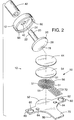
- Fig. 2 is an exploded view of the pointing device of Fig. 1.
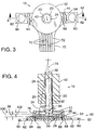
- Fig. 3 is a plan view of the pointing device of Fig. 1.
- Fig. 4 is a sectional view taken along the lines 4--4 of Fig. 3 showing in exaggerated detail the curvature of the bottom of the force transfer member and the thicknesses of the elastomeric adhesive, semiconductive layer, and conductive layers.
- Fig. 5 is a sectional view of an alternative embodiment of an actuator of the present invention.
- Fig. 6 is similar to Fig. 4 with certain details omitted for clarity and showing the actuator in phantom lines to indicate an exemplary operating condition.
- Fig. 7 is an isometric view of an alternative preferred pointing device of the present invention using a different method of retaining the actuator within the pointing device.
- Fig. 8 is a plan view of the pointing device of Fig. 7.
- Fig. 9 is a sectional view taken along the line 9--9 device of Fig. 8 showing in exaggerated detail the curvature of the bottom of the force transfer member and the thicknesses of the elastomeric adhesive, semiconductive layer, and conductive layers.
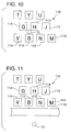
- Fig. 10 is a fragmentary plan view of a keyboard showing a pointing device of the present invention positioned between certain alphanumeric keys.
- Fig. 11 is a fragmentary plan view of a keyboard showing a pointing device of the present invention apart from the alphanumeric keys.
- pointing device 10 comprises a retainer shell 12 that partly encloses an actuator 20.
- Actuator 20 includes an arm 22 having a tip 24 at one end and a force transfer member 26 at the opposite end.
- Arm 22 is of cylindrical shape having a cross-sectional diameter 32.
- Force transfer member 26 is of spherical segment shape having an arcuate bottom surface 28 characterized by a bottom surface radius 34 and having a height 36.
- Arm 22 extends through a hole 40 in retainer shell 12 and is partly covered by a cap 42 that provides a frictional contact surface for a user's finger.
- Force transfer member 26 is attached by an elastomeric adhesive 44 to a force sensor 50.
- a preferred force sensor 50 includes an array of four force-sensing resistors 51, comprising a sensor substrate 52, a semiconductive layer 54, and conductors 56 in an interdigitated pattern. (In Fig. 4, the length of radius 34 is exaggerated; therefore, other components of pointing device 10 are also not drawn to scale.)
- Sensor substrate 52 includes two mounting flanges 60, each having a first mounting hole 62 for attaching pointing device 10 to a device such as a keyboard and a second mounting hole 64 for receiving a mounting finger 66 extending from shell 12 and secured to substrate 52.
- Sensor substrate 52 also includes an interconnect flange 70 having five contacts 72 for electrically connecting pointing device 10 to a host device. The five contacts 72, one for each of the four force-sensing resistors 51 and one common contact, are used to apply a voltage between interdigitated conductors 56 of each force-sensing resistors 51.
- a user operates pointing device 10 by manually applying a directional force 74 (Fig. 6) to tip 24 through cap 42 (not shown in Fig. 6).
- Force 74 provides a torque that tends to rock actuator 20 on bottom surface 28.
- tip 24 travels through a travel distance less than or equal to a maximum angular travel distance 80 and force transfer member 26 applies pressure through elastomeric adhesive 44 to sensor 50.
- maximum travel distance 80 be close or equal to zero.
- Pointing device 10 is characterized by a sensitivity parameter, which is defined as the change in electrical output of device 10 corresponding to a change in the direction and magnitude of applied force 74.
- the sensitivity of pointing device 10 depends upon the sensitivity of sensor 50 and upon the shape of actuator 20.
- An actuator 20 having a force transfer member 26 with a flat bottom, i.e., an infinite radius 34, would have a maximum travel distance 80 close to zero but would have low sensitivity.
- An actuator 20 having a relatively small radius 34 would have excellent sensitivity but an excessive maximum travel distance 80.
- force transfer member 26 is optimized to minimize the travel distance of arm 22 while maximizing the sensitivity of pointing device 10.
- a preferred force transfer member 26 has a curved bottom surface 28 with radius of curvature 34 equal to between twenty and thirty times cross-sectional diameter 32 of arm 22.
- arm 22 has a cross-sectional diameter 32 of 0.125 in (3.2 mm) and a bottom surface radius of curvature 34 of approximately 8.0 in (20.3 cm).
- a preferred force transfer member 26 is approximately 0.370 in (9.40 mm) wide and 0.030 in (0.76 mm) thick, and arm 22 is approximately 0.375 in (9.5 mm) long.
- Such a design results in a sensitive pointing device 10 having a very small maximum travel distance 80, resulting in a close approximation to an ergonomically desirable isometric pointing device.
- Fig. 5 shows another embodiment of an actuator 82 comprising a force transfer member 84 having a flat bottom surface 85 with a bevel 86.
- a preferred bevel angle 88 is between 1° and 2° with bevel 86 beginning approximately of the way between the center of the bottom surface and the edge of force transfer member 84.
- Bottom surface 85 can also include multiple bevels or a combination of flat, bevelled, and rounded areas.
- sensor 50 comprises a circular array of four force-sensing resistors 51, each configured as a ninety degree circular segment. The output of each pair of opposing force-sensing resistors 51 is compared, for example, by using a differential amplifier, to determine the two-dimensional components of force 74. With appropriate circuitry that would be obvious to skilled persons, the electrical signal from force-sensing resistors 51 can also be used to determine a downward component of force 74, thereby allowing measurement of forces in three dimensions.
- sensor 50 can be used with appropriate known circuitry to determine one, two, or three dimensional components of force 74.
- a circular array of three force-sensing resistors 51 each configured as a 120 degree circular segment, could be used to measure forces in two or three dimensions.
- a configuration of two or even one force-sensing resistors 51 could be used to measure forces in one or two dimensions.
- Force 74 is transferred at a single, contiguous area 90, the location and size of which changes as the applied force changes.
- a force transfer mechanism affords improved sensitivity and control compared to prior art force transfer mechanisms.
- a first portion of the rounded or bevelled bottom surface 28 presses into and compresses sensor 50 and a second, opposing portion tends to lift up from sensor 50 and thereby creates a tension in elastomeric adhesive 44.
- a pivot point 78 that changes position as the applied force changes, separates the first and second portions. The rocking of actuator 20 is slight enough so that the tension does not release force transfer member 26 from elastomeric adhesive 44.
- Retainer shell 12 defines the maximum travel distance 80 of arm 22 because hole 40 is sufficiently large to permit only a predetermined amount of travel distance of arm 22. Excessive travel of actuator 20 that would tend to free it from elastomeric adhesive 44 is thereby prevented.
- hole 40 has a diameter 92 (Fig. 4) of approximately 0.142 in (3.61 mm), resulting in an annular gap 94 having a width of between 0.008 in (0.203 mm) and 0.009 in (0.229 mm) between arm 22 and retainer shell 12.
- the space between elastomeric layer 44 and the inside top surface 96 defines an interior height 100.
- Interior height 100 is slightly greater than height 36 of force transfer member 26, thereby producing a small gap 102 that allows actuator 20 to rock in response to applied force 74.
- Gap 102 also allows actuator 20 to expand and contract as its temperature changes, without external constraints that would produce significant force on sensor 50.
- gap 102 is approximately 0.020 in (.508 mm) wide. Gap 102 is sufficiently small to prevent actuator 20 from detaching from elastomeric adhesive 44 by limiting the angular motion of actuator 20.
- a preferred actuator 20 is manufactured from a fiberglass-filled polycarbonate.
- Elastomeric adhesive 44 has adequate bond strength and is sufficiently elastic to allow force transfer member 26 to rock slightly without breaking the bond as arm 22 is displaced.
- a preferred elastomeric adhesive 44 comprises a layer approximately 0.005 in (0.127 mm) thick of VHB Adhesive from 3M, Minneapolis, Minnesota.
- Sensor 50 preferably comprises a four-zone, force-sensing resistor, as described in U.S. Pat. No. 4,489,302 to Eventoff for "Electronic Pressure Sensitive Force Transducer" and available from Interlink Electronics of Camarillo, California.
- the four force-sensing zones are either contiguous or actually overlap, as shown in Fig. 2.
- Other force sensors such as strain gauges or piezoelectric transducers, can also be used.
- Figs. 7, 8, and 9 show an alternative preferred embodiment of a pointing device 108 that uses a retainer ring 110 and a potting compound 112 in place of retainer shell 12.
- Retaining ring 110 serves to contain potting compound 112.
- Potting compound 112 is sufficiently soft that it does not significantly constrain actuator 20 from expanding or contracting as its temperature changes and, therefore, does not cause extraneous forces to be registered by sensor 50. Potting compound 112 is also sufficiently soft that it does not prevent small angular motion of actuator 20.
- Potting compound 112 does, however, restrict the maximum angular travel distance of arm 22, thereby preventing separation of actuator 20 from elastomeric adhesive 44. Potting compound 112 also prevents actuator 20 from falling out of pointing device 10 if the bond between elastomeric adhesive 44 and force transfer member 26 were to momentarily fail.
- a preferred potting compound is an electronics-grade silicone compound, such as that available from EMS, Indianapolis, Illinois.
- Pointing devices 10 and 108 are suited for use as an integrated pointing devices on a computer keyboard. Because of their environmental stability, pointing devices 10 and 108 are particularly well adapted for use on portable computers that are operated in varying environments. Using force-sensing resistors for sensor 50 results in an inexpensive yet stable force-sensing pointing device especially adapted to high-volume manufacturing.
- Fig. 10 shows, by way of example, pointing device 10 positioned between alphanumeric keys 114 of a keyboard 116.
- Fig. 11 shows, by way of example, pointing device 10 positioned apart from the alphanumeric keys 114 on the opposite side of a space bar 118 of a keyboard 120.
- Pointing device 10 could also be incorporated into one of alphanumeric keys 114 by modifying arm 22 and using a key cap in place of cap 42.
- the output of sensor 50 could be interpreted as an analog force or as a digital key input depending upon whether another key, such as the ALT key, is pressed simultaneously.
- the key could incorporate a separate mechanism to register a keystroke and act only as an analog force sensor under certain conditions, for example, when the key is maintained in a depressed condition.
- the output of the device can be used to change parameters other than cursor position.
- the device could be used to scroll through a number of selections or to change the pitch of an audio device.
- the shape of the actuator can be varied from that described above. The scope of the present invention should, therefore, be determined only by the following claims.
Landscapes
- Physics & Mathematics (AREA)
- General Physics & Mathematics (AREA)
- Engineering & Computer Science (AREA)
- Automation & Control Theory (AREA)
- Position Input By Displaying (AREA)
Claims (16)
- Analoge hebelartige Anzeigevorrichtung (10, 108), umfassend:ein Stellorgan (20, 82), das einen verlängerten Arm (22) umfaßt, welcher ein erstes und ein zweites Ende sowie ein Kraftübertragungselement (26, 84), das an dem zweiten Ende des verlängerten Armes (22) angebracht ist, aufweist, und einen Kraftsensor (50), der geeignet ist, eine auf das erste Ende des verlängerten Armes (22) ausgeübte und durch den verlängerten Arm (22) sowie das Kraftübertragungselement (26, 84) übertragene Kraft (74) zu erfassen, und gekennzeichnet durch:ein Verbindungselement (44), das einen elastomeren Klebstoff umfaßt, der zwischen dem Kraftsensor (50) und dem Kraftübertragungselement (26, 84) angeordnet ist, wobei der elastomere Klebstoff das Kraftübertragungselement (26, 84) an dem Kraftsensor (50) anbringt, das Kraftübertragungselement (26, 84) mit dem Kraftsensor (50) über das Verbindungselement (44) in Kontakt hält und, wenn sich die Umgebungstemperatur ändert, dem Kraftübertragungselement gestattet, sich in einer Richtung weg von dem Kraftsensor (50) zusammenzuziehen oder auszudehnen, ohne auf den Kraftsensor (50) eine Kraft auszuüben, welche den Sensorausgang wesentlich beeinflußt.
- Analoge hebelartige Anzeigevorrichtung (10, 108) nach Anspruch 1, bei welcher der verlängerte Arm (22) um einen Winkelbewegungsabstand unter der auf das erste Ende ausgeübten Kraft rotiert und weiterhin ein Halteelement (12, 112) umfaßt, welches den verlängerten Art umgibt und den Winkelbewegungsabstand des verlängerten Armes (22) begrenzt, um eine Trennung des Kraftübertragungselementes von dem Verbindungselement zu vermeiden.
- Analoge hebelartige Anzeigevorrichtung (10) nach Anspruch 2, bei welcher das Halteelement (12, 112) ein Gehäuse (12) umfaßt, das angeordnet ist, um den verlängerten Arm (22) zu umgeben.
- Analoge hebelartige Anzeigevorrichtung (108) nach Anspruch 2, bei welcher das Halteelement (12, 112) einen Vergießverbund (112) umfaßt.
- Analoge hebelartige Anzeigevorrichtung (10, 108) nach einem der vorhergehenden Ansprüche, bei welcher das Kraftübertragungselement (26) durch eine zylindrisch gewölbte Bodenfläche (28) gekennzeichnet ist.
- Analoge hebelartige Anzeigevorrichtung (10, 108) nach einem der Ansprüche 1 bis 4, bei welcher das Kraftübertragungselement (84) durch eine abgekantete Bodenfläche (86) gekennzeichnet ist.
- Analoge hebelartige Anzeigevorrichtung (10, 108) nach einem der vorhergehenden Ansprüche, bei welcher der verlängerte Arm (22) einen Querschnittsdurchmesser (32) aufweist und das Kraftübertragungselement (26, 84) einen Radius (34) von zwischen 20- und 30-fachem Querschnittsdurchmesser (32) des Elementes mit verlängertem Arm (22) aufweist.
- Analoge hebelartige Anzeigevorrichtung (10, 108) nach einem der vorhergehenden Ansprüche, bei welcher das Kraftübertragungselement (26, 84) eine Kraft auf den Sensor (50) über eine einzelne zusammenhängende Fläche (90), deren Position in Antwort auf eine Kraftänderung variiert, überträgt.
- Analoge hebelartige Anzeigevorrichtung (10, 108) nach einem der vorhergehenden Ansprüche, bei welcher der Sensor (50) einen kraftabtastenden Widerstand umfaßt.
- Analoge hebelartige Anzeigevorrichtung (10, 108) nach einem der vorhergehenden Ansprüche, bei welcher der kraftabtastende Widerstand ein Teil eines Feldes von vier kraftabtastenden Widerständen umfaßt.
- Analoge hebelartige Anzeigevorrichtung (10, 108) nach einem der Ansprüche 1 bis 8, bei welcher der Sensor (50) einen piezoelektrischen Sensor umfaßt.
- Tastatur, umfassend:einen Satz von alphanumerischen Tasten, undeine analoge hebelartige Anzeigevorrichtung, wie in jedem vorhergehenden Anspruch beansprucht.
- Tastatur nach Anspruch 12, bei welcher die analoge hebelartige Anzeigevorrichtung in einem Zwischenraum, welcher die alphanumerischen Tasten trennt, angeordnet ist.
- Tastatur nach Anspruch 13, bei welcher die analoge hebelartige Anzeigevorrichtung von den alphanumerischen Tasten getrennt angeordnet ist.
- Verfahren zur Herstellung einer Cursorsteuervorrichtung, bei welcher ein Kraftsensor (50) mit einem Stellorgan (20, 82), das ein Kraftübertragungselement (26, 84) und einen verlängerten Arm (22) aufweist, verbunden ist, wobei das Verfahren gekennzeichnet ist durch Anordnen eines elastomeren Klebstoffes (44) benachbart zu dem Sensor und Anbringen des Stellorgans an dem elastomeren Klebstoff (44), wobei der elastomere Klebstoff (44) ein Verbindungselement darstellt, welches das Kraftübertragungselement (26, 84) an dem Kraftsensor (50) anbringt, das Kraftübertragungselement (26, 84) mit dem Kraftsensor (50) über das Verbindungselement in Kontakt hält und, wenn sich die Umgebungstemperatur ändert, dem Kraftübertragungselement (26, 84) gestattet, sich in einer Richtung weg von dem Kraftsensor (50) zusammenzuziehen oder auszudehnen, ohne auf den Sensor (50) eine Kraft auszuüben, welche den Sensorausgang wesentlich beeinflußt, und
Anordnen eines Halteelementes um den verlängerten Arm (22), das eine Winkelabweichung des verlängerten Armes (22) begrenzt, um eine Trennung des Kraftübertragungselementes von dem Verbindungselement (44) zu vermeiden. - Verfahren zur Steuerung einer Cursorbewegung auf einem Bildschirm durch Verwendung einer Richtungsanzeigevorrichtung, wie in einem der Ansprüche 1 bis 11 beansprucht.
Applications Claiming Priority (3)
| Application Number | Priority Date | Filing Date | Title |
|---|---|---|---|
| US08/168,632 US5659334A (en) | 1993-12-15 | 1993-12-15 | Force-sensing pointing device |
| US168632 | 1993-12-15 | ||
| PCT/US1994/014577 WO1995016975A1 (en) | 1993-12-15 | 1994-12-13 | Force-sensing pointing device |
Publications (2)
| Publication Number | Publication Date |
|---|---|
| EP0759199A1 EP0759199A1 (de) | 1997-02-26 |
| EP0759199B1 true EP0759199B1 (de) | 1998-06-03 |
Family
ID=22612310
Family Applications (1)
| Application Number | Title | Priority Date | Filing Date |
|---|---|---|---|
| EP95905992A Expired - Lifetime EP0759199B1 (de) | 1993-12-15 | 1994-12-13 | Druckfühlende hinweisanordnung |
Country Status (5)
| Country | Link |
|---|---|
| US (2) | US5659334A (de) |
| EP (1) | EP0759199B1 (de) |
| JP (1) | JP3501457B2 (de) |
| DE (1) | DE69410828T2 (de) |
| WO (1) | WO1995016975A1 (de) |
Families Citing this family (141)
| Publication number | Priority date | Publication date | Assignee | Title |
|---|---|---|---|---|
| US5889670A (en) | 1991-10-24 | 1999-03-30 | Immersion Corporation | Method and apparatus for tactilely responsive user interface |
| US6906700B1 (en) | 1992-03-05 | 2005-06-14 | Anascape | 3D controller with vibration |
| US6222525B1 (en) | 1992-03-05 | 2001-04-24 | Brad A. Armstrong | Image controllers with sheet connected sensors |
| US6285356B1 (en) | 1999-02-19 | 2001-09-04 | Brad A. Armstrong | Displacement joystick with compression-sensitive sensors |
| US6433771B1 (en) * | 1992-12-02 | 2002-08-13 | Cybernet Haptic Systems Corporation | Haptic device attribute control |
| US6437771B1 (en) | 1995-01-18 | 2002-08-20 | Immersion Corporation | Force feedback device including flexure member between actuator and user object |
| US5805140A (en) | 1993-07-16 | 1998-09-08 | Immersion Corporation | High bandwidth force feedback interface using voice coils and flexures |
| US5721566A (en) | 1995-01-18 | 1998-02-24 | Immersion Human Interface Corp. | Method and apparatus for providing damping force feedback |
| US5659334A (en) * | 1993-12-15 | 1997-08-19 | Interlink Electronics, Inc. | Force-sensing pointing device |
| WO1996011434A1 (en) * | 1994-10-07 | 1996-04-18 | Interlink Electronics, Inc. | Isometric pointing device with integrated click and method therefor |
| US6100874A (en) | 1995-11-17 | 2000-08-08 | Immersion Corporation | Force feedback mouse interface |
| US6639581B1 (en) | 1995-11-17 | 2003-10-28 | Immersion Corporation | Flexure mechanism for interface device |
| US5825308A (en) | 1996-11-26 | 1998-10-20 | Immersion Human Interface Corporation | Force feedback interface having isotonic and isometric functionality |
| JP3396701B2 (ja) | 1996-05-01 | 2003-04-14 | Smk株式会社 | 相対操作量の入力装置 |
| US8674932B2 (en) | 1996-07-05 | 2014-03-18 | Anascape, Ltd. | Image controller |
| US20100124634A1 (en) * | 1996-09-26 | 2010-05-20 | Slotta Mark R | Cushioned cap with annular portion and method for forming same |
| US6686911B1 (en) | 1996-11-26 | 2004-02-03 | Immersion Corporation | Control knob with control modes and force feedback |
| US7489309B2 (en) | 1996-11-26 | 2009-02-10 | Immersion Corporation | Control knob with multiple degrees of freedom and force feedback |
| US20020018048A1 (en) * | 1997-02-04 | 2002-02-14 | Seffernick Lewis L. | Z-axis pointing stick with esd protection |
| US5905485A (en) * | 1997-02-13 | 1999-05-18 | Breed Automotive Technology, Inc. | Controller with tactile sensors and method of fabricating same |
| US5875682A (en) * | 1997-03-20 | 1999-03-02 | Caterpillar Inc. | Operator controlled electrical output signal device |
| US6184866B1 (en) * | 1997-09-29 | 2001-02-06 | Varatouch Technology Incorporated | Pointing device |
| US6313826B1 (en) * | 1998-04-07 | 2001-11-06 | Varatouch Technology Incorporated | Pointing device with non-spring return mechanism |
| US6211861B1 (en) | 1998-06-23 | 2001-04-03 | Immersion Corporation | Tactile mouse device |
| US6040823A (en) * | 1997-12-02 | 2000-03-21 | Cts | Computer keyboard having top molded housing with rigid pointing stick integral and normal to front surface of housing as one unit part to be used with strain sensors in navigational control |
| DE19753867B4 (de) * | 1997-12-04 | 2007-07-05 | Linde Ag | Bedienhebel |
| US6115030A (en) * | 1997-12-18 | 2000-09-05 | International Business Machines Corporation | Trackpoint device |
| US6195082B1 (en) * | 1998-03-31 | 2001-02-27 | International Business Machines Corporation | Low noise circuit board for trackpoint pointing device |
| US6509890B1 (en) * | 1998-03-31 | 2003-01-21 | International Business Machines Corporation | Mini-TrackPoint IV pointing device |
| US6137475A (en) * | 1998-05-21 | 2000-10-24 | Cts Corporation | Pointing stick having an interposer connecting layer |
| GB0027260D0 (en) | 2000-11-08 | 2000-12-27 | Koninl Philips Electronics Nv | An image control system |
| US6184462B1 (en) | 1998-06-29 | 2001-02-06 | Caterpillar Inc. | Apparatus for retaining a printed circuit board |
| JP2000122742A (ja) * | 1998-06-29 | 2000-04-28 | Caterpillar Inc | コントロ―ルスティックに付与される力を制御する装置 |
| US6256012B1 (en) * | 1998-08-25 | 2001-07-03 | Varatouch Technology Incorporated | Uninterrupted curved disc pointing device |
| US6198473B1 (en) | 1998-10-06 | 2001-03-06 | Brad A. Armstrong | Computer mouse with enhance control button (s) |
| US6359613B1 (en) | 1998-10-07 | 2002-03-19 | Cts Corporation | Pointing stick having chip resistors |
| US6239786B1 (en) * | 1998-11-30 | 2001-05-29 | Cts Corporation | Pointing stick with top mounted z-axis sensor |
| JP2000207102A (ja) * | 1999-01-18 | 2000-07-28 | Alps Electric Co Ltd | キ―ボ―ド装置 |
| US6331849B1 (en) | 1999-02-25 | 2001-12-18 | Cts Corporation | Integrated surface-mount pointing device |
| US6304247B1 (en) * | 1999-03-02 | 2001-10-16 | Cts Corporation | Piezoelectric stick pointing device |
| US6295050B1 (en) | 1999-03-18 | 2001-09-25 | International Business Machines Corporation | Joy stick pointing device to control the movement of a graphical element on a computer display monitor |
| EP1058177A1 (de) * | 1999-06-04 | 2000-12-06 | Alps Electric Co., Ltd. | Eingabeeinrichtung fur Spielvorrichtung |
| GB2351561B (en) * | 1999-06-30 | 2003-10-22 | Nokia Mobile Phones Ltd | Joystick controller |
| TW463078B (en) * | 1999-07-05 | 2001-11-11 | Alps Electric Co Ltd | Multidirectional input device |
| US6227066B1 (en) | 1999-07-26 | 2001-05-08 | Mpc Products Corporation | Joystick centering device supporting multiple compound torque profiles |
| EP1129443B1 (de) | 1999-09-10 | 2012-10-24 | Sony Computer Entertainment Inc. | Fernbedienungsvorrichtung mit druckempfindlichen tasten |
| US6717568B1 (en) * | 1999-09-10 | 2004-04-06 | Sony Computer Entertainment Inc. | Method of controlling the movement of a position indicating item, storage medium on which a program implementing said method is stored, and electronic device |
| US6323840B1 (en) | 1999-09-17 | 2001-11-27 | Cts Corporation | Surface-mount pointing device |
| JP2001318758A (ja) | 2000-03-03 | 2001-11-16 | Sony Computer Entertainment Inc | 操作装置および同装置の信号出力調整方法 |
| US6313731B1 (en) | 2000-04-20 | 2001-11-06 | Telefonaktiebolaget L.M. Ericsson | Pressure sensitive direction switches |
| TW509866B (en) * | 2000-05-31 | 2002-11-11 | Darfon Electronics Corp | Pointing apparatus capable of increasing sensitivity |
| GB2367113A (en) | 2000-09-25 | 2002-03-27 | Nokia Mobile Phones Ltd | A control device having a strain sensor and a resilient means |
| US7084854B1 (en) | 2000-09-28 | 2006-08-01 | Immersion Corporation | Actuator for providing tactile sensations and device for directional tactile sensations |
| JP2002200343A (ja) * | 2000-10-30 | 2002-07-16 | Sony Computer Entertainment Inc | 記録媒体、プログラム、方法、プログラム実行システムおよびプログラム実行装置 |
| JP2002202853A (ja) * | 2000-10-30 | 2002-07-19 | Sony Computer Entertainment Inc | 記録媒体、プログラム、方法、プログラム実行システムおよびプログラム実行装置 |
| TW501772U (en) * | 2000-12-01 | 2002-09-01 | Darfon Electronics Corp | Point stick and notebook computer using the same |
| US6967643B2 (en) * | 2001-01-31 | 2005-11-22 | Cts Corporation | Tactile feedback for cursor control device |
| US6873316B2 (en) | 2001-02-01 | 2005-03-29 | Cts Corporation | Suppression of cursor control during tactile feedback operation |
| US6909354B2 (en) | 2001-02-08 | 2005-06-21 | Interlink Electronics, Inc. | Electronic pressure sensitive transducer apparatus and method for manufacturing same |
| US6520699B2 (en) * | 2001-02-16 | 2003-02-18 | Toshiyasu Abe | Keyboard |
| US6781576B2 (en) | 2001-03-14 | 2004-08-24 | Sensation, Inc. | Wireless input apparatus and method using a three-dimensional pointing device |
| US6970159B2 (en) | 2001-06-25 | 2005-11-29 | Gray Robin S | Mouse printing device with integrated touch pad buttons |
| US6999009B2 (en) * | 2001-08-31 | 2006-02-14 | Logitech Europe S.A. | Sensing keys for keyboard |
| US6879316B2 (en) * | 2001-12-11 | 2005-04-12 | Logitech Europe, S.A. | Pointing device with pressure sensitive resistor |
| JP2003296016A (ja) * | 2002-03-29 | 2003-10-17 | Minebea Co Ltd | ポインティングデバイスの電極構造 |
| US7369115B2 (en) | 2002-04-25 | 2008-05-06 | Immersion Corporation | Haptic devices having multiple operational modes including at least one resonant mode |
| US7161580B2 (en) * | 2002-04-25 | 2007-01-09 | Immersion Corporation | Haptic feedback using rotary harmonic moving mass |
| US6826042B2 (en) * | 2002-05-03 | 2004-11-30 | Hewlett-Packard Development Company, L.P. | Input device and methods and systems for same |
| JP3960132B2 (ja) * | 2002-06-06 | 2007-08-15 | 松下電器産業株式会社 | 多方向操作スイッチおよびこれを用いた多方向入力装置 |
| JP2004037350A (ja) | 2002-07-05 | 2004-02-05 | Nitta Ind Corp | 抵抗型センサ |
| DE10243223A1 (de) * | 2002-09-17 | 2004-03-25 | Völckers, Oliver | Bedienelement für elektronische Geräte zur Betätigung von Sensoren und ein Verfahren zur Auswahl von in einem elektronischen Speicher enthaltenen Funktionen und zur Anzeige der ausgewählten Funktion mittels eines Cursors |
| US7050045B2 (en) * | 2003-01-07 | 2006-05-23 | Interlink Electronics, Inc. | Miniature highly manufacturable mouse pointing device |
| US7591783B2 (en) | 2003-04-01 | 2009-09-22 | Boston Scientific Scimed, Inc. | Articulation joint for video endoscope |
| US20040199052A1 (en) | 2003-04-01 | 2004-10-07 | Scimed Life Systems, Inc. | Endoscopic imaging system |
| US20050245789A1 (en) | 2003-04-01 | 2005-11-03 | Boston Scientific Scimed, Inc. | Fluid manifold for endoscope system |
| US7578786B2 (en) | 2003-04-01 | 2009-08-25 | Boston Scientific Scimed, Inc. | Video endoscope |
| US8118732B2 (en) | 2003-04-01 | 2012-02-21 | Boston Scientific Scimed, Inc. | Force feedback control system for video endoscope |
| US6937227B2 (en) * | 2003-07-14 | 2005-08-30 | Iowa State University Research Foundation, Inc. | Hand-held pointing device |
| US7616188B1 (en) | 2003-08-22 | 2009-11-10 | Logitech Europe S.A. | Mouse roller with horizontal scrolling and horizontal tilting switch |
| US7570247B2 (en) * | 2003-11-24 | 2009-08-04 | Avago Technologies Ecbu Ip (Singapore) Pte. Ltd. | Modular assembly for a self-indexing computer pointing device |
| US7429976B2 (en) * | 2003-11-24 | 2008-09-30 | Avago Technologies Ecbu Ip (Singapore) Pte. Ltd. | Compact pointing device |
| US7129854B2 (en) * | 2004-02-10 | 2006-10-31 | Motorola, Inc. | Electronic device with force sensing key |
| WO2005113892A1 (en) * | 2004-05-14 | 2005-12-01 | Stowe Woodward, Llc | Nip press sensing system including a sensor strip having sensor interface electronics associated therewith and methods of operating the same |
| US7113179B2 (en) * | 2004-06-23 | 2006-09-26 | Interlink Electronics, Inc. | Force sensing resistor with calibration element and method of manufacturing same |
| WO2006039267A2 (en) | 2004-09-30 | 2006-04-13 | Boston Scientific Scimed, Inc. | Multi-functional endoscopic system for use in electrosurgical applications |
| US8083671B2 (en) | 2004-09-30 | 2011-12-27 | Boston Scientific Scimed, Inc. | Fluid delivery system for use with an endoscope |
| EP1799096A2 (de) | 2004-09-30 | 2007-06-27 | Boston Scientific Scimed, Inc. | System und verfahren zur entfernung von verstopfungen |
| AU2005291952A1 (en) | 2004-09-30 | 2006-04-13 | Boston Scientific Limited | Adapter for use with digital imaging medical device |
| US7479106B2 (en) | 2004-09-30 | 2009-01-20 | Boston Scientific Scimed, Inc. | Automated control of irrigation and aspiration in a single-use endoscope |
| US7241263B2 (en) | 2004-09-30 | 2007-07-10 | Scimed Life Systems, Inc. | Selectively rotatable shaft coupler |
| US7597662B2 (en) | 2004-09-30 | 2009-10-06 | Boston Scientific Scimed, Inc. | Multi-fluid delivery system |
| US7508372B2 (en) * | 2004-10-29 | 2009-03-24 | Logitech Europe S.A. | Tilt roller for control device |
| US7221113B1 (en) | 2004-11-10 | 2007-05-22 | The Creative Train Company, Llc | Touch-sensitive model train controls |
| US7456821B2 (en) * | 2004-11-30 | 2008-11-25 | Immersion Corporation | User interface device |
| US20060146018A1 (en) * | 2005-01-04 | 2006-07-06 | Arneson Theodore R | Joystick with tactile feedback |
| US7978173B2 (en) * | 2005-01-14 | 2011-07-12 | Avago Technologies Ecbu Ip (Singapore) Pte. Ltd. | Pointing device including a moveable puck with mechanical detents |
| US7586480B2 (en) | 2005-02-28 | 2009-09-08 | Avago Technologies Ecbu Ip (Singapore) Pte. Ltd. | Hybrid pointing device |
| US8097003B2 (en) | 2005-05-13 | 2012-01-17 | Boston Scientific Scimed, Inc. | Endoscopic apparatus with integrated variceal ligation device |
| US7846107B2 (en) | 2005-05-13 | 2010-12-07 | Boston Scientific Scimed, Inc. | Endoscopic apparatus with integrated multiple biopsy device |
| US8052597B2 (en) | 2005-08-30 | 2011-11-08 | Boston Scientific Scimed, Inc. | Method for forming an endoscope articulation joint |
| US20070068785A1 (en) * | 2005-09-26 | 2007-03-29 | Taiwan Pwl Corporation | Rocker level assembly |
| US7701440B2 (en) * | 2005-12-19 | 2010-04-20 | Avago Technologies Ecbu Ip (Singapore) Pte. Ltd. | Pointing device adapted for small handheld devices having two display modes |
| US20070146311A1 (en) * | 2005-12-22 | 2007-06-28 | Logitech Europe S.A. | Roller with single piece carriage and open front hook |
| US7791596B2 (en) * | 2005-12-27 | 2010-09-07 | Interlink Electronics, Inc. | Touch input device having interleaved scroll sensors |
| US7967759B2 (en) | 2006-01-19 | 2011-06-28 | Boston Scientific Scimed, Inc. | Endoscopic system with integrated patient respiratory status indicator |
| US8888684B2 (en) | 2006-03-27 | 2014-11-18 | Boston Scientific Scimed, Inc. | Medical devices with local drug delivery capabilities |
| US7955255B2 (en) | 2006-04-20 | 2011-06-07 | Boston Scientific Scimed, Inc. | Imaging assembly with transparent distal cap |
| US8202265B2 (en) | 2006-04-20 | 2012-06-19 | Boston Scientific Scimed, Inc. | Multiple lumen assembly for use in endoscopes or other medical devices |
| US20070247446A1 (en) * | 2006-04-25 | 2007-10-25 | Timothy James Orsley | Linear positioning input device |
| US7889176B2 (en) * | 2006-07-18 | 2011-02-15 | Avago Technologies General Ip (Singapore) Pte. Ltd. | Capacitive sensing in displacement type pointing devices |
| US7573464B2 (en) * | 2006-07-20 | 2009-08-11 | Interlink Electronics, Inc. | Shape adaptable resistive touchpad |
| JP2008059212A (ja) * | 2006-08-30 | 2008-03-13 | Alps Electric Co Ltd | 入力装置 |
| US8199134B2 (en) * | 2006-08-30 | 2012-06-12 | Alps Electric Co., Ltd. | Input device |
| US8421602B2 (en) | 2006-09-13 | 2013-04-16 | Savant Systems, Llc | Remote control unit for a programmable multimedia controller |
| US20080275417A1 (en) * | 2007-05-03 | 2008-11-06 | Steven Ray Gilbert | Tampon with patterned end and method and apparatus for making same |
| US8232963B2 (en) * | 2007-08-27 | 2012-07-31 | Avago Technologies Ecbu Ip (Singapore) Pte. Ltd. | Control and data entry apparatus |
| US20090058802A1 (en) * | 2007-08-27 | 2009-03-05 | Avago Technologies Ecbu Ip (Singapore) Pte. Ltd. | Input device |
| US7978175B2 (en) * | 2007-11-23 | 2011-07-12 | Avago Technologies Ecbu Ip (Singapore) Pte. Ltd. | Magnetic re-centering mechanism for a capacitive input device |
| US20090135157A1 (en) * | 2007-11-27 | 2009-05-28 | Avago Technologies Ecbu Ip (Singapore) Pte. Ltd. | Capacitive Sensing Input Device with Reduced Sensitivity to Humidity and Condensation |
| US8427441B2 (en) | 2008-12-23 | 2013-04-23 | Research In Motion Limited | Portable electronic device and method of control |
| EP2202619A1 (de) * | 2008-12-23 | 2010-06-30 | Research In Motion Limited | Tragbare elektronische Vorrichtung, die eine taktile, berührungsempfindliche Eingabevorrichtung enthält, und Verfahren zu deren Steuerung |
| US8384680B2 (en) | 2008-12-23 | 2013-02-26 | Research In Motion Limited | Portable electronic device and method of control |
| US8107947B1 (en) | 2009-06-24 | 2012-01-31 | Sprint Spectrum L.P. | Systems and methods for adjusting the volume of a remote push-to-talk device |
| JP2011008204A (ja) * | 2009-06-29 | 2011-01-13 | Gk Tech Inc | ディスプレイ装置 |
| US8542105B2 (en) | 2009-11-24 | 2013-09-24 | Immersion Corporation | Handheld computer interface with haptic feedback |
| US8587422B2 (en) | 2010-03-31 | 2013-11-19 | Tk Holdings, Inc. | Occupant sensing system |
| US9007190B2 (en) | 2010-03-31 | 2015-04-14 | Tk Holdings Inc. | Steering wheel sensors |
| JP5759230B2 (ja) | 2010-04-02 | 2015-08-05 | ティーケー ホールディングス,インコーポレーテッド | 手センサを有するステアリング・ホイール |
| US8983732B2 (en) | 2010-04-02 | 2015-03-17 | Tk Holdings Inc. | Steering wheel with hand pressure sensing |
| JP5161338B2 (ja) * | 2011-05-09 | 2013-03-13 | 株式会社ソニー・コンピュータエンタテインメント | キーボード |
| TWM430646U (en) * | 2011-08-02 | 2012-06-01 | Howay Corp | Capacitive pointing device |
| KR101836499B1 (ko) * | 2011-12-02 | 2018-03-09 | 현대자동차주식회사 | 햅틱형 로봇 핸들시스템 |
| WO2013154720A1 (en) | 2012-04-13 | 2013-10-17 | Tk Holdings Inc. | Pressure sensor including a pressure sensitive material for use with control systems and methods of using the same |
| WO2014043664A1 (en) | 2012-09-17 | 2014-03-20 | Tk Holdings Inc. | Single layer force sensor |
| WO2014120984A2 (en) | 2013-01-30 | 2014-08-07 | David Paul Smith | Operator controlled electrical output signal device with variable feel and hold feedback and automated calibration and learnable performance optimization |
| US10627918B2 (en) * | 2014-02-13 | 2020-04-21 | Microsoft Technology Licensing, Llc | Low-profile pointing stick |
| US10528155B2 (en) | 2014-02-13 | 2020-01-07 | Microsoft Technology Licensing, Llc | Low-profile pointing stick |
| WO2017075201A1 (en) * | 2015-10-30 | 2017-05-04 | Northwestern University | Dielectrostrictive sensors for shear stress measurement, process monitoring, and quality examination of viscoelastic materials |
| RU192186U1 (ru) * | 2018-12-21 | 2019-09-05 | Ооо "Мера-Тсп" | Силовой джойстик |
| WO2020255858A1 (ja) * | 2019-06-19 | 2020-12-24 | アルプスアルパイン株式会社 | 多方向入力装置 |
| US11934588B1 (en) | 2021-02-21 | 2024-03-19 | Meta Platforms Technologies, Llc | Controller for sensing downward force applied to a movable thumbstick and providing a haptic response thereto, and methods of use thereof |
Family Cites Families (16)
| Publication number | Priority date | Publication date | Assignee | Title |
|---|---|---|---|---|
| US3464531A (en) * | 1967-05-16 | 1969-09-02 | Us Army | Manual electronic keyboard |
| US4168405A (en) * | 1978-03-02 | 1979-09-18 | Indak Manufacturing Corp. | Electrical reversing switch |
| US4246452A (en) * | 1979-01-05 | 1981-01-20 | Mattel, Inc. | Switch apparatus |
| US4489302A (en) * | 1979-09-24 | 1984-12-18 | Eventoff Franklin Neal | Electronic pressure sensitive force transducer |
| US4313113A (en) * | 1980-03-24 | 1982-01-26 | Xerox Corporation | Cursor control |
| US4680577A (en) * | 1983-11-28 | 1987-07-14 | Tektronix, Inc. | Multipurpose cursor control keyswitch |
| US4748441A (en) * | 1986-09-17 | 1988-05-31 | Brzezinski Stephen R M | Multiple function control member |
| GB2205941B (en) * | 1987-06-18 | 1991-08-07 | Ibm | Manually-operated control device |
| US4949080A (en) * | 1988-12-12 | 1990-08-14 | Mikan Peter J | Computer keyboard control accessory |
| US5231386A (en) * | 1990-07-24 | 1993-07-27 | Home Row, Inc. | Keyswitch-integrated pointing assembly |
| WO1992009996A1 (en) * | 1990-11-29 | 1992-06-11 | Lexmark International, Inc. | Analog input device located in the primary typing area of a keyboard |
| US5159159A (en) * | 1990-12-07 | 1992-10-27 | Asher David J | Touch sensor and controller |
| JPH06511340A (ja) * | 1991-10-04 | 1994-12-15 | マイクロメッド・システムズ・インコーポレイテッド | ポケット大のコンピュータ入力装置および方法 |
| US5174101A (en) * | 1991-11-14 | 1992-12-29 | Rabitsch Thermon D | Protective cover for combine skid plates |
| JP3060793B2 (ja) * | 1993-02-25 | 2000-07-10 | 松下電器産業株式会社 | 位置入力装置およびこれを用いた入力装置 |
| US5659334A (en) * | 1993-12-15 | 1997-08-19 | Interlink Electronics, Inc. | Force-sensing pointing device |
-
1993
- 1993-12-15 US US08/168,632 patent/US5659334A/en not_active Expired - Lifetime
-
1994
- 1994-12-13 DE DE69410828T patent/DE69410828T2/de not_active Expired - Lifetime
- 1994-12-13 JP JP51699495A patent/JP3501457B2/ja not_active Expired - Fee Related
- 1994-12-13 EP EP95905992A patent/EP0759199B1/de not_active Expired - Lifetime
- 1994-12-13 WO PCT/US1994/014577 patent/WO1995016975A1/en not_active Ceased
-
1997
- 1997-08-18 US US08/912,733 patent/US5828363A/en not_active Expired - Lifetime
Also Published As
| Publication number | Publication date |
|---|---|
| US5659334A (en) | 1997-08-19 |
| DE69410828D1 (de) | 1998-07-09 |
| JPH09507315A (ja) | 1997-07-22 |
| US5828363A (en) | 1998-10-27 |
| DE69410828T2 (de) | 1999-01-28 |
| WO1995016975A1 (en) | 1995-06-22 |
| EP0759199A1 (de) | 1997-02-26 |
| JP3501457B2 (ja) | 2004-03-02 |
Similar Documents
| Publication | Publication Date | Title |
|---|---|---|
| EP0759199B1 (de) | Druckfühlende hinweisanordnung | |
| US5521596A (en) | Analog input device located in the primary typing area of a keyboard | |
| US5640178A (en) | Pointing device | |
| US5591924A (en) | Force and torque converter | |
| US5541622A (en) | Miniature isometric joystick | |
| JP4909080B2 (ja) | 小型ポインティングデバイス | |
| US5905485A (en) | Controller with tactile sensors and method of fabricating same | |
| US5407285A (en) | Pointing stick in a computer keyboard for cursor control | |
| US20020018048A1 (en) | Z-axis pointing stick with esd protection | |
| US6437772B1 (en) | Capacitive pointing stick apparatus with floating conductive cone for symbol manipulation in a graphical user interface | |
| US5550339A (en) | Variable speed tactile switch | |
| US4747313A (en) | Tactile sensor | |
| US6239786B1 (en) | Pointing stick with top mounted z-axis sensor | |
| JP4213239B2 (ja) | 歪み集中機構としての基板を持つz軸感応ポインティング・スティック | |
| US6753850B2 (en) | Low profile cursor control device | |
| JP3039286B2 (ja) | 荷重センサ | |
| US5455556A (en) | Single station cursor device suitable for keyboards | |
| US20020054015A1 (en) | Control device | |
| JP4459428B2 (ja) | 操作量検出装置 | |
| WO1989006023A1 (en) | An apparatus for controlling a movable reference point on a display | |
| WO1992009996A1 (en) | Analog input device located in the primary typing area of a keyboard | |
| JP3193556B2 (ja) | 座標入力装置 | |
| WO1990007786A2 (en) | Finger mouse computer input device | |
| JPH0658269B2 (ja) | 触覚センサ | |
| JP2000267802A (ja) | ポインティングスティック用厚膜回路基板 |
Legal Events
| Date | Code | Title | Description |
|---|---|---|---|
| PUAI | Public reference made under article 153(3) epc to a published international application that has entered the european phase |
Free format text: ORIGINAL CODE: 0009012 |
|
| 17P | Request for examination filed |
Effective date: 19961009 |
|
| AK | Designated contracting states |
Kind code of ref document: A1 Designated state(s): DE GB |
|
| GRAG | Despatch of communication of intention to grant |
Free format text: ORIGINAL CODE: EPIDOS AGRA |
|
| 17Q | First examination report despatched |
Effective date: 19970612 |
|
| GRAG | Despatch of communication of intention to grant |
Free format text: ORIGINAL CODE: EPIDOS AGRA |
|
| GRAH | Despatch of communication of intention to grant a patent |
Free format text: ORIGINAL CODE: EPIDOS IGRA |
|
| GRAH | Despatch of communication of intention to grant a patent |
Free format text: ORIGINAL CODE: EPIDOS IGRA |
|
| GRAA | (expected) grant |
Free format text: ORIGINAL CODE: 0009210 |
|
| AK | Designated contracting states |
Kind code of ref document: B1 Designated state(s): DE GB |
|
| REF | Corresponds to: |
Ref document number: 69410828 Country of ref document: DE Date of ref document: 19980709 |
|
| PLBE | No opposition filed within time limit |
Free format text: ORIGINAL CODE: 0009261 |
|
| STAA | Information on the status of an ep patent application or granted ep patent |
Free format text: STATUS: NO OPPOSITION FILED WITHIN TIME LIMIT |
|
| 26N | No opposition filed | ||
| REG | Reference to a national code |
Ref country code: GB Ref legal event code: IF02 |
|
| PGFP | Annual fee paid to national office [announced via postgrant information from national office to epo] |
Ref country code: GB Payment date: 20091209 Year of fee payment: 16 |
|
| PGFP | Annual fee paid to national office [announced via postgrant information from national office to epo] |
Ref country code: DE Payment date: 20091222 Year of fee payment: 16 |
|
| GBPC | Gb: european patent ceased through non-payment of renewal fee |
Effective date: 20101213 |
|
| REG | Reference to a national code |
Ref country code: DE Ref legal event code: R119 Ref document number: 69410828 Country of ref document: DE Effective date: 20110701 |
|
| PG25 | Lapsed in a contracting state [announced via postgrant information from national office to epo] |
Ref country code: DE Free format text: LAPSE BECAUSE OF NON-PAYMENT OF DUE FEES Effective date: 20110701 Ref country code: GB Free format text: LAPSE BECAUSE OF NON-PAYMENT OF DUE FEES Effective date: 20101213 |