EP0762542A2 - Diversité d'antennes - Google Patents
Diversité d'antennes Download PDFInfo
- Publication number
- EP0762542A2 EP0762542A2 EP96113314A EP96113314A EP0762542A2 EP 0762542 A2 EP0762542 A2 EP 0762542A2 EP 96113314 A EP96113314 A EP 96113314A EP 96113314 A EP96113314 A EP 96113314A EP 0762542 A2 EP0762542 A2 EP 0762542A2
- Authority
- EP
- European Patent Office
- Prior art keywords
- antenna
- receiving
- wavelength
- matching
- circuit
- Prior art date
- Legal status (The legal status is an assumption and is not a legal conclusion. Google has not performed a legal analysis and makes no representation as to the accuracy of the status listed.)
- Withdrawn
Links
Images


Classifications
-
- H—ELECTRICITY
- H04—ELECTRIC COMMUNICATION TECHNIQUE
- H04B—TRANSMISSION
- H04B7/00—Radio transmission systems, i.e. using radiation field
- H04B7/02—Diversity systems; Multi-antenna system, i.e. transmission or reception using multiple antennas
- H04B7/10—Polarisation diversity; Directional diversity
-
- H—ELECTRICITY
- H01—ELECTRIC ELEMENTS
- H01Q—ANTENNAS, i.e. RADIO AERIALS
- H01Q21/00—Antenna arrays or systems
- H01Q21/24—Combinations of antenna units polarised in different directions for transmitting or receiving circularly and elliptically polarised waves or waves linearly polarised in any direction
- H01Q21/245—Combinations of antenna units polarised in different directions for transmitting or receiving circularly and elliptically polarised waves or waves linearly polarised in any direction provided with means for varying the polarisation
-
- H—ELECTRICITY
- H01—ELECTRIC ELEMENTS
- H01Q—ANTENNAS, i.e. RADIO AERIALS
- H01Q21/00—Antenna arrays or systems
- H01Q21/29—Combinations of different interacting antenna units for giving a desired directional characteristic
Definitions
- the present invention relates to a diversity antenna circuit which receives signals with two units of antenna and uses the received signals for switching them, and more particularly to a diversity antenna circuit which suppresses mutual interference in each antenna' s reception and thus allows selection or switching to the antenna having higher receiving sensitivity.
- a plurality of paths is generated when a transmitted electric wave propagates through space and the plurality of paths interfere each other at a receiving terminal and the received electric field strength fluctuates from time to time, and this phenomenon is called fading.
- a propagation path in land mobile communications becomes a multi-path propagation path, and so called the fading occurs in which envelope and phase of a received wave fluctuate according to the law of Rayleigh distribution and the law of homogeneous distribution, respectively.
- diversity As a technique for alleviating the effects of fading, there is a technology called diversity.
- the technology in which a plurality of receiving systems having no correlation concerning the receiving points are provided is called space diversity
- the technology in which a plurality of receiving systems having no correlation concerning the frequencies is called frequency diversity
- polarization diversity the technology in which a plurality of receiving systems having no correlation concerning the planes of polarization
- an antenna for a mobile station in mobile communications omnibearing is required for the horizontal plane so that a receiving level will not change according to the difference in a direction in which an electric wave arrives, also, a beam faces the substantially horizontal direction because an electric wave arrives in the substantially the horizontal direction, that the construction should be rigid, and that the form of the antenna is well harmonized with external appearance of the mobile body.
- a uni-pole antenna based on simple construction a sleeve antenna little affected by a conductive plate and having excellent directivity, a 5/8 wavelength antenna, a reversed F-shaped antenna which is compact and well suited to incorporation in a portable unit, or the like.
- the diversity antenna circuit With the diversity antenna circuit according to the present invention, two receiving systems having no correlation between each other about a plane of polarization are provided therein. Fluctuation during propagation of electric wave is reduced by switching electric power received thereby with a switching means. More specifically, a plane of vertical polarization of electric wave is mainly received by the first antenna, and a plane of horizontal polarization of electric wave is mainly received by the second antenna. The electric field strength of a received signal received by the first antenna and second antenna is detected by the receiving means. One end of the first antenna and second antenna each is connected to the receiving means by ON or OFF control of the first switching means and the second switching means based on the electric field strength in the switching control means. The receiving means is separated from the other end of the first antenna and second antenna.
- Impedance matching between the first antenna and the receiving means is executed by the first matching means, and impedance matching between the second antenna and the receiving means is executed by the second matching means.
- a vertical plane of polarization of an electric wave is mainly received by a first antenna 101
- a horizontal plane of polarization of an electric wave is mainly received by a second antenna 102
- an electric field strength of the signal received by the first antenna 101 or second antenna 102 is detected by a receiving means 121
- the receiving means 121 is connected to either one of the first antenna 1001 or second antenna 102 and the other of the first antenna 101 and second antenna 102 is separated from the receiving means according to ON control or OFF control provided by a first switching means 116 as well as by a second switching means based on the electric field strength.
- impedance matching between the first antenna 101 and the receiving means 121 is executed by a first matching means 109
- impedance matching between the second antenna 102 and the receiving means 121 is executed by the second matching means 108.
- the first antenna 101 is a 1/4 wavelength whip antenna installed in the vertical direction
- the second antenna 102 is a half- wavelength dipole antenna installed in the horizontal direction and including a 1/4 wavelength first conductor section 103 and a 1/4 wavelength second conductor 104.
- the first matching means 109 is preferably a 1/4 wavelength first strip line having one edge thereof connected to a feeding point of the 1/4 wavelength whip antenna 101
- the second matching means 108 is a 1/4 wavelength feeder line comprising two lines in parallel to each other and including the first feeder line section 106 having the other edge thereof connected to a feeding point of the 1/4 wavelength first conductor section 103 and the second feeder line section 107 having the other end thereof connected to a feeding point of the 1/4 wavelength second feeder section 104.
- the first transfer means 110 is a 1/4 wavelength second strip line having the other end thereof connected to the 1/4 wavelength first strip line 109
- the second transfer means 111 is a 1/4 wavelength third strip line having the other end thereof connected to the first feeder line section 106 or the second feeder line section 107.
- a vertical plane of polarization of electric wave is received by the 1/4 wavelength whip antenna 101, and a horizontal plane of polarization of electric wave is received by the half-wavelength dipole antenna 102, so that the one having higher receiving sensitivity can accurately be selected and switched thereto by the switching control means 122.
- Impedance matching between the first antenna as well as the second antenna and the receiving means 121 is accurately executed by the first matching means 109 and the second matching means 108.
- first transfer means 110 comprising a 1/4 wavelength second strip line and a second transfer means 111 comprising a 1/4 waveform third strip line
- flexible circuit designing such as setting said strip lines so that a capacity component or an induction component or the like due to elements realizing a first switching means 115 and second switching means 116 are accommodated by the 1/4 wavelength second strip line 110 and 1/4 wavelength third strip line 111 becomes possible.
- This makes it possible to realize a diversity antenna circuit having excellent characteristics which can reduce loss when connected or disconnected.
- the first switching means 115 when it is determined that electric field strength of a signal received by the first antenna 101 is higher than that by the second antenna 102, the first switching means 115 is turned OFF and the second switching means 116 is turned ON by a switching control means 112.
- the first switching means 115 is turned ON and the second switching means 116 is turned OFF.
- a receiving system based on the second antenna 102 is disconnected and a receiving system based on the first antenna 101 is connected for receiving operation by the receiving system to be executed.
- the receiving system based on the first antenna 101 is disconnected and the receiving system based on the second antenna 102 is connected.
- a connection point 131 between the first antenna 101 and the first matching means 109 is connected to or disconnected from a connection point 133 between the first transfer means 110 and the receiving means 121 according to ON or OFF control provided by the first switching means 115.
- a connection point between the second antenna 102 and the second matching means 108 is connected to or disconnected from a connection point 133 between the second transfer means 111 and the receiving means 121 according to ON control or OFF control provided by the switching means 116.
- the end of the first matching means 109 not connected to the first antenna 101 is shorted or opened to control, a connection point between the first antenna 101 and the first matching means 109.
- a feeding point of the first antenna 101 is opened or shorted
- another end of the second matching means 108 not connected to the second antenna 102 is shorted or opened, and a connection point between the second antenna 102 and the second matching means 108, namely a feeding point of the second antenna 102 is opened or shorted.
- the diversity antenna circuit is packaged on a multilayered substrate, and the 1/4 wavelength first conductor section 103 as well as the first feeder line section 106 and the 1/4 wavelength second conductor section 104 as well as the second feeder line section 107 are packaged on different layers respectively.
- a diversity antenna circuit As described above, by packaging a diversity antenna circuit on a circuit board, it can be used as an antenna for a mobile station, such as a portable telephone, for which a high degree of miniaturization is required, and a diversity antenna circuit suited to incorporation in a portable unit can be realized. Also by packaging a half-wavelength dipole antenna 102 and the 1/4 wavelength feeder line 108 comprising 2 lines in parallel to each other on different layers respectively, it becomes possible to make an element width larger and also to reduce loss. For this reason, a diversity antenna circuit, which has excellent performance in a broader frequency band area, can be realized.
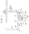
- Fig. 1 is a block diagram showing the diversity antenna circuit according to an embodiment of the present invention.
- the diversity antenna circuit of the present invention comprises a vertically positioned 1/4 wavelength whip antenna 101, a horizontally positioned half-wavelength dipole antenna 102, a 1/4 wavelength feeder line 108 comprising two lines in parallel to each other, a 1/4 wavelength first strip line 109, a 1/4 wavelength second strip line 110, a 1/4 wavelength third strip line 111, a 1/4 wavelength second strip line 110, a 1/4 wavelength third strip line 111, a diode 115, a diode 116, a receiving circuit 121, and a CPU 122.
- the vertically positioned 1/4 wavelength whip antenna 101 receives mainly a vertical plane of polarization of electric wave.
- the horizontally positioned half-wavelength dipole antenna 102 comprises a first conductor section 103 and a second conductor section 104, and mainly receives a horizontal plane of polarization of electric wave.
- the 1/4 wavelength first strip line 109 is for matching impedance of the vertically positioned 1/4 wavelength whip antenna 101 to that of the receiving circuit 121.
- the 1/4 wavelength feeder line 108 comprising two line in parallel to each other comprises a first feeder line section 106 connected to the first conductor section 103 and a second feeder line section 107 connected to the second conductor section 104, and is for matching impedance of the horizontally positioned half-wavelength dipole antenna 102 to that of the receiving circuit 121.
- the 1/4 wavelength second strip line 110 transfers a signal received from the vertically positioned 1/4 wavelength whip antenna 101 to the receiving circuit 121 and also has a matching function for open/short-controlling a connection point 133 simultaneously when the diode 115 is ON/OFF-controlled.
- the 1/4 wavelength third strip line 111 transfers a signal received from the horizontally positioned half-wavelength dipole antenna 102 to the receiving circuit 121, and also has a matching function for open/short-controlling the connection point 133 simultaneously when the diode 116 is ON/OFF-controlled.
- the receiving circuit 121 has at least a function for detecting an electric field strength of a received signal, and the result of detection of the electric field strength is reported to the CPU 122.
- the CPU 122 determines with which antenna (receiving system) a signal should be received according to the electric field strength of the received signal obtained in the receiving circuit 121, and a bias-control in regular or reverse direction of the diodes 115 and 116 is executed by control signals 125 and 126 respectively.
- the CPU 122 provides a reverse-directional bias control for the diode 115 and also provides a regular-directional bias-control for the diode 116 when it is determined that electric field strength of a signal received by the vertically positioned 1/4 wavelength whip antenna 110 is higher than that by the horizontally positioned half-wavelength dipole antenna 102 so that a connection point 131 between the vertically positioned 1/4 wavelength whip antenna 101 and the 1/4 wavelength strip line 109 is shorted and at the same time a connection point between the horizontally positioned half-wavelength dipole antenna 102 and the 1/4 wavelength feeder line 108 comprising two lines in parallel to each other is set in the open state.
- the CPU 122 provides a regular-directional control for the diode 115 and also provides a reverse-directional bias control for the diode 116 when it is determined that the electric field strength of a signal received by the horizontally positioned half-wavelength dipole antenna 102 is higher than that by the vertically positioned 1/4 wavelength whip antenna 101, so that a connection point 131 between the vertically positioned 1/4 wavelength whip antenna 101 and the 1/4 wavelength first strip line 109 is set in the open state and at the same time a connection point between the horizontally positioned half-wavelength dipole antenna 102 and the 1/4 wavelength feeder line 108 comprising two lines in parallel to each other is shorted.
- the diversity antenna circuit of the present embodiment has the configuration of polarization diversity, and two receiving systems of the vertically positioned 1/4 wavelength whip antenna 101 and the horizontally positioned half-wavelength dipole antenna 102 are required to have no correlation with each other concerning plane of polarization.
- testing is performed for checking the characteristics by means of simulation, assuming location and configuration of the vertically positioned 1/4 wavelength whip antenna 101 and the horizontally positioned half-wavelength dipole antenna 102 as follows.
- Fig. 2A is an equivalent circuit in the state where impedance at the feeding point of horizontally positioned half-wavelength dipole antenna 102 is made higher (100 [ ⁇ ]) and the antenna is separated from the vertical one
- Fig. 2B is an equivalent circuit in the case where impedance at the feeding point of the vertically positioned 1/4 wavelength whip antenna 101 is made higher (100 [ ⁇ ]) and the antenna is separated from the horizontal one.
- FIG. 3A When the horizontally positioned half-wavelength dipole antenna 102 is separated therefrom, the result of simulation according to Fig. 2A is shown in Fig. 3.
- Fig. 3A and Fig. 3B is a field strength pattern, and Fig. 3A shows orientation of radiated electric field strength on a horizontal plane thereof, while Fig. 3B shows that on a vertical plane thereof.
- the field strength pattern (V in the figure) of the vertically positioned 1/4 wavelength whip antenna 101 is dominant as compared with that (H in the figure) of the horizontally positioned half-wavelength dipole antenna 102, so that it can be said that receiving by the vertically positioned 1/4 wavelength whip antenna 101 is hardly affected by the horizontally positioned half-wavelength dipole antenna 102.
- the impedance at the feeding point may be set to 100 ⁇ or more.
- Fig. 4A and Fig. 4B show a field strength pattern
- Fig. 4A shows orientation of radiated electric field strength on a horizontal plane thereof
- Fig. 4B shows that on a vertical plane thereof.
- the field strength pattern (H in the figure) of the horizontally positioned half-wavelength dipole antenna 102 is dominant as compared with that (V in the figure) of the vertically positioned 1/4 wavelength whip antenna 101, so that it can be said that receiving by the horizontally positioned half- wavelength dipole antenna 102 is hardly affected by the vertically positioned 1/4 wavelength whip antenna 101.
- the impedance at the feeding point may be set to 100 ⁇ or more.
- the switching control section comprises diodes 115 and 116, such as an HSU277, and a CPU 122, and the CPU 122 determines from the electric field strength of a received signal obtained by the CPU via the receiving circuit 121, and bias control for a regular direction/reverse direction to the diodes 115 and 116 is executed according to control signals 125 and 126 therefrom respectively.
- the other end 132 of the 1/4 wavelength first strip line 109 not connected to the vertically positioned 1/4 wavelength whip antenna 101 is short/open-controlled according to a bias control for a regular direction/a reverse direction to the diode 115, and with this feature, when it is seen from the connection point 132, the connection point 131 between the vertically positioned 1/4 wavelength whip antenna 101 and the 1/4 wavelength first strip line 109, namely the feeding point of the vertically positioned 1/4 wavelength whip antenna 101 is open/short-controlled, and also the connection point 133 between the 1/4 wavelength second strip line 110 and the receiving circuit 121 is controlled for opening or shorting.
- the other end 134 of the 1/4 wavelength feeder line 108 comprising two lines in parallel to each other not connected to the horizontally positioned half-wavelength dipole antenna 102 is controlled for shorting or opening according to a bias control for a regular direction or a reverse direction to the diode 116.
- the CPU 122 determines from the electric field strength obtained by the receiving circuit 121 that an electric field strength of a signal received by the vertically positioned 1/4 wavelength whip antenna 101 is higher than that by the horizontally positioned half-wavelength dipole antenna 102, the receiving system based on the horizontally positioned half-wavelength dipole antenna 102 is separated therefrom by reverse biasing to the diode 115 and forward biasing the diode 116, and also the receiving system based on the vertically positioned 1/4 wavelength whip antenna 101 is connected thereto, whereby receiving operation is executed.
- the CPU 122 determines that an electric field strength of a signal received by the horizontally positioned half-wavelength dipole antenna 102 is higher than that in receiving by the vertically positioned 1/4 wavelength whip antenna 101, the receiving system based on the 1/4 wavelength whip antenna 101 is separated therefrom by forward biasing the diode 115 and a reverse biasing the diode 116, and also the receiving system based on the horizontally positioned half-wavelength dipole antenna 102 is connected thereto, whereby receiving operation is executed.
- the matching means comprises a 1/4 wavelength first strip line 109 for matching impedance of the vertically positioned 1/4 wavelength whip antenna 101 to the switch section for switching described later and a 1/4 wavelength feeder line 108 comprising two lines in parallel to each other having a first feeder line section 106 connected to the first conductor section 103 and a second feeder line section 107 connected to the second conductor 104 and for matching impedance of the horizontally positioned half-wavelength dipole antenna 102 to the switching section for switching.
- a matching means for the diversity antenna circuit is, firstly, to match the impedance of the antenna to an output from the switch section for switching, and secondly, to make higher the impedance at the feeding point when separated therefrom.
- the circuit satisfying these requests is a 1/4 wavelength strip line.
- the impedance of the horizontally positioned half-wavelength dipole antenna 102 is 72 [ ⁇ ]
- the impedance of the vertically positioned 1/4 wavelength whip antenna 101 is 36 [ ⁇ ].
- the output from the switch section may match the antenna impedance during passing through, and the impedance at the feeding point may be high when it is separated.
- a 1/4 wavelength strip line is realized with the 1/4 wavelength feeder line 108 comprising two lines in parallel to each other. Namely, if configured with an identical impedance and two lines in parallel to each other with 1/4 wavelength having the same length, these are equivalent to each other.
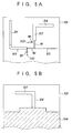
- FIG. 5A is a pattern view of the surface thereof, while Fig. 5B is a pattern view of the rear surface thereof.
- the vertically positioned 1/4 wavelength whip antenna 101, second conductor section 104 of the horizontally positioned half-wavelength dipole antenna 102, second feeder line section 107 of the 1/4 wavelength feeder line 108 comprising two lines in parallel to each other, 1/4 wavelength first strip line 109, a 1/4 wavelength second strip line 110, 1/4 wavelength third strip line 111, diode 115, diode 116, and feeder line 123 to the receiving circuit 121 are packaged on the surface thereof.
- the first conductor section 103 of the horizontally positioned half-wavelength dipole antenna 102, first feeder line section 106 of the 1/4 wavelength feeder line 108 comprising two lines in parallel to each other, and a grand pattern 704 are packaged on the rear surface thereof.
- the reference numerals 702 and 703 each indicate a through hole.
- first conductor section 103 as well as the first feeder line section 106 and the second conductor section 104 as well as second feeder line section 107 each constituting the half-wavelength dipole antenna 102 and 1/4 wavelength feeder line 108 comprising two lines in parallel to each other are packaged in different layers.
- the width of these elements can be made larger, and losses can be reduced, and for this reason, a diversity antenna circuit with excellent performance can be realized at a wider frequency band.
- two receiving systems having no correlation between each other about a plane of polarization are provided therein. Fluctuation during propagation of electric wave is reduced by switching electric power received thereby with a switching means. More specifically, a plane of vertical polarization of electric wave is mainly received by the first antenna, a plane of horizontal polarization of electric wave is mainly received by the second antenna, an electric field strength of a received signal received by the first antenna and second antenna is detected by the receiving means, one end of the first antenna and second antenna each is connected to the receiving means by ON control or OFF control of the first switching means and the second switching means based on the electric field strength in the switching control means.
- the receiving means is separated from the other end of the first antenna and second antenna, impedance matching between the first antenna and the receiving means is executed by the first matching means, and impedance matching between the second antenna and the receiving means is executed by the second matching means.
- a diversity antenna circuit in which interference between each other in each of receiving operations can accordingly be suppressed and accurate selection of the antenna one having higher receiving sensitivity.
- the first antenna is a 1/4 wavelength whip antenna installed in a vertical direction
- the second antenna is a half-wavelength dipole antenna installed in a horizontal direction and including a 1/4 wavelength first conductor section and a 1/4 wavelength second conductor section.
- the first matching means is a 1/4 wavelength first strip line having one end thereof connected to a feeding point of the 1/4 wavelength whip antenna.
- the second matching means is a 1/4 wavelength feeding line comprising two lines parallel to each other including a first feeder line section having one end thereof connected to a feeding point of the 1/4 wavelength first conductor section and a second feeder line section having one end connected to a feeding point of 1/4 wavelength second conductor section.
- the first transfer means is a 1/4 wavelength second strip line connected to the other end of the 1/4 wavelength first strip line
- the second transfer means is a 1/4 wavelength third strip line connected to the other end of the first feeder line section or the second feeder line section.
- the circuit according to the second feature comprises the first transfer means through the 1/4 wavelength strip line and the second transfer means through the 1/4 wavelength third strip line.
- Flexible circuit design such that the strip line is set is possible so that a capacity component and an induction component with elements realizing the first switching means and the second switching means can be absorbed in the 1/4 wavelength second strip line and the 1/4 wavelength third strip line. Losses produced by connection thereof and separation therefrom can be reduced, and for this reason, a diversity antenna circuit with excellent performance described above can be realized.
- the switching control means turns OFF the first switching means and ON the second switching means when it determines that the electric field strength of a signal received by the first antenna is higher than that by the second antenna.
- the switching means turns ON the first switching means and OFF the second switching means when it determines that the electric field strength of a signal received by he second antenna is higher than that by the first antenna, so that the receiving system with the second antenna is separated from the circuit, the receiving system with the first antenna is connected thereto.
- Reception by the receiving system is executed when it is determined that the electric field received by the first antenna is higher, while the receiving system with the first antenna is separated from the circuit, the receiving system with the second antenna is connected thereto.
- Reception by the receiving system is executed when it is determined that the electric field in receiving with the second antenna is higher, thus selection and switching of a receiving system being executed without fail.
- a connection point between the first antenna and the first matching means is connected to or disconnected from a connection point between the first transfer means and the receiving means according to ON or OFF control by the first switching means, while a connection point between the second antenna and the second matching means is connected to and disconnected from a connection point between the second transfer means and the receiving means according to ON or OFF control by the second switching means, and the connection point between the first antenna and the first matching means.
- the feeding point of the first antenna is open/short-controlled according to ON/OFF control by the first switching means, while the connection point between the second antenna and the second matching means.
- the feeding point of the second antenna is open/short-controlled according to ON/OFF control by the second switching means, so that selection and switching of a receiving system by the switching control means can be executed without fail. Losses produced by connection thereto and separation therefrom can be reduced, and for this reason, a diversity antenna circuit with excellent performance described above can be realized.
- the diversity antenna circuit is packaged on a multilayered substrate, and the 1/4 wavelength first conductor section as well as the first feeder line section and the 1/4 wavelength second conductor section as well as the second feeder line section are packaged in different layers respectively, so that it is possible that the circuit is applied to an antenna for a mobile station required a high degree of miniaturization of a potable telephone unit or the like.
- a compact diversity antenna circuit suitable to incorporation in a potable unit can thus be realized.
- the width of elements can be made greater by packaging a half-wavelength dipole antenna and a 1/4 wavelength feeder line comprising two lines in parallel to each other in different layers, and losses can be reduced. For this reason, a diversity antenna circuit with excellent performance at a wider frequency band can be realized.
Landscapes
- Engineering & Computer Science (AREA)
- Computer Networks & Wireless Communication (AREA)
- Signal Processing (AREA)
- Radio Transmission System (AREA)
- Variable-Direction Aerials And Aerial Arrays (AREA)
- Details Of Aerials (AREA)
- Support Of Aerials (AREA)
Applications Claiming Priority (3)
| Application Number | Priority Date | Filing Date | Title |
|---|---|---|---|
| JP21763395 | 1995-08-25 | ||
| JP217633/95 | 1995-08-25 | ||
| JP7217633A JPH0964639A (ja) | 1995-08-25 | 1995-08-25 | ダイバーシチ・アンテナ回路 |
Publications (2)
| Publication Number | Publication Date |
|---|---|
| EP0762542A2 true EP0762542A2 (fr) | 1997-03-12 |
| EP0762542A3 EP0762542A3 (fr) | 1999-06-09 |
Family
ID=16707332
Family Applications (1)
| Application Number | Title | Priority Date | Filing Date |
|---|---|---|---|
| EP96113314A Withdrawn EP0762542A3 (fr) | 1995-08-25 | 1996-08-20 | Diversité d'antennes |
Country Status (5)
| Country | Link |
|---|---|
| US (1) | US6104356A (fr) |
| EP (1) | EP0762542A3 (fr) |
| JP (1) | JPH0964639A (fr) |
| AU (1) | AU6210896A (fr) |
| SG (1) | SG88725A1 (fr) |
Cited By (8)
| Publication number | Priority date | Publication date | Assignee | Title |
|---|---|---|---|---|
| EP1185336A1 (fr) * | 1999-04-30 | 2002-03-13 | Medtronic, Inc. | Systeme de telemesure pour dispositifs medicaux implantables |
| WO2002035645A1 (fr) * | 2000-10-27 | 2002-05-02 | Telefonaktiebolaget L M Ericsson (Publ) | Systeme d'antenne de terminal mobile |
| WO2003007422A1 (fr) * | 2001-07-13 | 2003-01-23 | Red Snake Radio Technology Ab | Dispositif d'antenne multipoints |
| WO2003067710A1 (fr) * | 2002-02-04 | 2003-08-14 | Jan Bergman | Systeme d'evaluation tridimensionnelle |
| EP1148584A3 (fr) * | 2000-03-30 | 2005-01-05 | Sony Corporation | Appareil et procédé de radiocommunication |
| WO2007066890A1 (fr) * | 2005-11-03 | 2007-06-14 | Samsung Electronics Co., Ltd. | Systeme d'antenne a diversite de polarisation |
| EP1557903A4 (fr) * | 2002-09-26 | 2007-08-01 | Matsushita Electric Industrial Co Ltd | Antenne de dispositif de terminal radio et dispositif de terminal radio |
| US10135156B2 (en) | 2015-09-04 | 2018-11-20 | Stellenbosch University | Multi-mode composite antenna |
Families Citing this family (43)
| Publication number | Priority date | Publication date | Assignee | Title |
|---|---|---|---|---|
| JP4053144B2 (ja) * | 1998-07-10 | 2008-02-27 | 日本電業工作株式会社 | 偏波共用アンテナ |
| JP3629176B2 (ja) | 2000-02-09 | 2005-03-16 | 株式会社東芝 | 携帯無線端末 |
| JP3528745B2 (ja) * | 2000-03-06 | 2004-05-24 | 日本電気株式会社 | 携帯無線機 |
| JP4522019B2 (ja) * | 2001-06-21 | 2010-08-11 | 富士通テン株式会社 | ディジタルテレビ放送用受信機およびアンテナ |
| FR2828584A1 (fr) * | 2001-08-10 | 2003-02-14 | Thomson Licensing Sa | Dispositif pour la reception et/ou l'emission de signaux a diversite de rayonnement |
| US7405697B2 (en) * | 2003-03-18 | 2008-07-29 | Zhinong Ying | Compact diversity antenna |
| ATE385052T1 (de) * | 2003-03-18 | 2008-02-15 | Sony Ericsson Mobile Comm Ab | Kompakte diversity-antenne |
| KR100531879B1 (ko) * | 2003-07-09 | 2005-11-29 | 엘지전자 주식회사 | 휴대폰의 고주파 수신회로 |
| KR100539650B1 (ko) * | 2003-07-10 | 2005-12-29 | 푸바 오토모티브 게엠베하 운트 코. 카게 | 차량의 위성 및/또는 지상 무선 신호용 수신 안테나 장치 |
| JP2007528665A (ja) * | 2004-03-11 | 2007-10-11 | テレフオンアクチーボラゲット エル エム エリクソン(パブル) | アンテナダイバーシチシステムにおいてフィーダの数を低減させる方法、装置、基地局、及び基地局サイト |
| JP4491654B2 (ja) | 2004-06-15 | 2010-06-30 | テレフオンアクチーボラゲット エル エム エリクソン(パブル) | アンテナダイバシティ装置とその方法 |
| US7652632B2 (en) | 2004-08-18 | 2010-01-26 | Ruckus Wireless, Inc. | Multiband omnidirectional planar antenna apparatus with selectable elements |
| US7696946B2 (en) * | 2004-08-18 | 2010-04-13 | Ruckus Wireless, Inc. | Reducing stray capacitance in antenna element switching |
| US7498996B2 (en) | 2004-08-18 | 2009-03-03 | Ruckus Wireless, Inc. | Antennas with polarization diversity |
| US7292198B2 (en) | 2004-08-18 | 2007-11-06 | Ruckus Wireless, Inc. | System and method for an omnidirectional planar antenna apparatus with selectable elements |
| US7193562B2 (en) | 2004-11-22 | 2007-03-20 | Ruckus Wireless, Inc. | Circuit board having a peripheral antenna apparatus with selectable antenna elements |
| US7965252B2 (en) | 2004-08-18 | 2011-06-21 | Ruckus Wireless, Inc. | Dual polarization antenna array with increased wireless coverage |
| US7362280B2 (en) | 2004-08-18 | 2008-04-22 | Ruckus Wireless, Inc. | System and method for a minimized antenna apparatus with selectable elements |
| US7880683B2 (en) | 2004-08-18 | 2011-02-01 | Ruckus Wireless, Inc. | Antennas with polarization diversity |
| US8031129B2 (en) | 2004-08-18 | 2011-10-04 | Ruckus Wireless, Inc. | Dual band dual polarization antenna array |
| US7358912B1 (en) | 2005-06-24 | 2008-04-15 | Ruckus Wireless, Inc. | Coverage antenna apparatus with selectable horizontal and vertical polarization elements |
| US7646343B2 (en) | 2005-06-24 | 2010-01-12 | Ruckus Wireless, Inc. | Multiple-input multiple-output wireless antennas |
| US7893882B2 (en) * | 2007-01-08 | 2011-02-22 | Ruckus Wireless, Inc. | Pattern shaping of RF emission patterns |
| US7339390B2 (en) * | 2005-05-31 | 2008-03-04 | International Business Machines Corporation | Systems and methods for controlling of electro-migration |
| US7292195B2 (en) * | 2005-07-26 | 2007-11-06 | Motorola, Inc. | Energy diversity antenna and system |
| EP1986344A1 (fr) * | 2006-02-14 | 2008-10-29 | Matsushita Electric Industrial Co., Ltd. | Appareil radio mobile |
| US7639106B2 (en) | 2006-04-28 | 2009-12-29 | Ruckus Wireless, Inc. | PIN diode network for multiband RF coupling |
| JP4952789B2 (ja) | 2007-04-12 | 2012-06-13 | 日本電気株式会社 | 二偏波アンテナ |
| JP4951746B2 (ja) * | 2008-07-01 | 2012-06-13 | 株式会社デンソーウェーブ | 携帯型rfidリーダライタ |
| US8217843B2 (en) | 2009-03-13 | 2012-07-10 | Ruckus Wireless, Inc. | Adjustment of radiation patterns utilizing a position sensor |
| US8698675B2 (en) | 2009-05-12 | 2014-04-15 | Ruckus Wireless, Inc. | Mountable antenna elements for dual band antenna |
| JP4819153B2 (ja) * | 2009-08-31 | 2011-11-24 | 日本電業工作株式会社 | 偏波共用アンテナ |
| US9407012B2 (en) | 2010-09-21 | 2016-08-02 | Ruckus Wireless, Inc. | Antenna with dual polarization and mountable antenna elements |
| JP5514779B2 (ja) * | 2011-08-30 | 2014-06-04 | 日本電業工作株式会社 | 偏波共用アンテナ |
| US8756668B2 (en) | 2012-02-09 | 2014-06-17 | Ruckus Wireless, Inc. | Dynamic PSK for hotspots |
| US9634403B2 (en) | 2012-02-14 | 2017-04-25 | Ruckus Wireless, Inc. | Radio frequency emission pattern shaping |
| US10186750B2 (en) | 2012-02-14 | 2019-01-22 | Arris Enterprises Llc | Radio frequency antenna array with spacing element |
| US8947308B2 (en) * | 2012-02-17 | 2015-02-03 | Skycross, Inc. | Method and apparatus for controlling an antenna |
| US9092610B2 (en) | 2012-04-04 | 2015-07-28 | Ruckus Wireless, Inc. | Key assignment for a brand |
| US9570799B2 (en) | 2012-09-07 | 2017-02-14 | Ruckus Wireless, Inc. | Multiband monopole antenna apparatus with ground plane aperture |
| JP2014064130A (ja) * | 2012-09-20 | 2014-04-10 | Panasonic Corp | アンテナ装置 |
| CN105051975B (zh) | 2013-03-15 | 2019-04-19 | 艾锐势有限责任公司 | 用于双频带定向天线的低频带反射器 |
| CN109149134B (zh) * | 2018-08-20 | 2020-11-24 | 深圳市万普拉斯科技有限公司 | 移动终端及天线系统的切换方法 |
Family Cites Families (26)
| Publication number | Priority date | Publication date | Assignee | Title |
|---|---|---|---|---|
| US3521284A (en) * | 1968-01-12 | 1970-07-21 | John Paul Shelton Jr | Antenna with pattern directivity control |
| JPS511109A (ja) * | 1974-06-21 | 1976-01-07 | Fujitsu Ltd | Deetahenkanhoshiki |
| JPS5263644A (en) * | 1975-11-19 | 1977-05-26 | Matsushita Electric Ind Co Ltd | Microwave device |
| JPS52101949A (en) * | 1976-02-23 | 1977-08-26 | Matsushita Electric Ind Co Ltd | Antenna apparatus |
| JPS5870642A (ja) * | 1981-10-22 | 1983-04-27 | Toyota Motor Corp | 自動車用受信装置 |
| US4434425A (en) * | 1982-02-02 | 1984-02-28 | Gte Products Corporation | Multiple ring dipole array |
| JPS611102A (ja) * | 1984-01-13 | 1986-01-07 | Japan Radio Co Ltd | 偏波切換えマイクロストリツプアンテナ回路 |
| JPH01183201A (ja) * | 1988-01-18 | 1989-07-21 | Mitsubishi Electric Corp | プリント化ダイポールアンテナ |
| US4890118A (en) * | 1988-12-27 | 1989-12-26 | Hughes Aircraft Company | Compensated microwave feed horn |
| JPH03196705A (ja) * | 1989-12-26 | 1991-08-28 | Hitachi Ltd | マイクロ波集積回路とそれを用いたアクティブアンテナ及びコンバータ |
| US5208602A (en) * | 1990-03-12 | 1993-05-04 | Raytheon Company | Cavity backed dipole antenna |
| EP0454585B1 (fr) * | 1990-04-27 | 1994-08-03 | Nippon Telegraph And Telephone Corporation | Sélection d'antenne pour un système de réception diversity |
| JPH0490639A (ja) * | 1990-08-03 | 1992-03-24 | Nippon Telegr & Teleph Corp <Ntt> | 偏波共用受信装置 |
| JPH0490640A (ja) * | 1990-08-03 | 1992-03-24 | Nippon Telegr & Teleph Corp <Ntt> | 偏波共用受信装置 |
| JP2646408B2 (ja) * | 1991-04-01 | 1997-08-27 | 国際電信電話株式会社 | 妨害波除去方式及び装置 |
| CA2071714A1 (fr) * | 1991-07-15 | 1993-01-16 | Gary George Sanford | Antenne electroniquement reconfigurable |
| JP3138934B2 (ja) * | 1991-12-09 | 2001-02-26 | 日本電信電話株式会社 | スペースダイバーシチ方式 |
| JPH05219007A (ja) * | 1992-02-04 | 1993-08-27 | Nec Eng Ltd | 交差偏波干渉除去装置 |
| EP0562607B1 (fr) * | 1992-03-27 | 1999-09-08 | Asahi Glass Company Ltd. | Antenne fonctionnant en diversité sur vitre de véhicule |
| JPH06232601A (ja) * | 1993-01-29 | 1994-08-19 | Mitsubishi Electric Corp | マイクロ波スイッチ回路 |
| JPH06260955A (ja) * | 1993-03-05 | 1994-09-16 | Maspro Denkoh Corp | コンバータ |
| JPH06334565A (ja) * | 1993-03-25 | 1994-12-02 | Matsushita Electric Ind Co Ltd | 移動体識別装置用応答器 |
| JPH07176942A (ja) * | 1993-12-20 | 1995-07-14 | Fujitsu General Ltd | 直線偏波受信用アンテナ |
| JPH07183725A (ja) * | 1993-12-24 | 1995-07-21 | Nec Corp | 携帯型無線受信機のアンテナ装置 |
| US5486836A (en) * | 1995-02-16 | 1996-01-23 | Motorola, Inc. | Method, dual rectangular patch antenna system and radio for providing isolation and diversity |
| US5583511A (en) * | 1995-06-06 | 1996-12-10 | Hughes Missile Systems Company | Stepped beam active array antenna and radar system employing same |
-
1995
- 1995-08-25 JP JP7217633A patent/JPH0964639A/ja active Pending
-
1996
- 1996-08-15 AU AU62108/96A patent/AU6210896A/en not_active Abandoned
- 1996-08-20 EP EP96113314A patent/EP0762542A3/fr not_active Withdrawn
- 1996-08-21 SG SG9610508A patent/SG88725A1/en unknown
- 1996-08-26 US US08/704,008 patent/US6104356A/en not_active Expired - Fee Related
Cited By (9)
| Publication number | Priority date | Publication date | Assignee | Title |
|---|---|---|---|---|
| EP1185336A1 (fr) * | 1999-04-30 | 2002-03-13 | Medtronic, Inc. | Systeme de telemesure pour dispositifs medicaux implantables |
| EP1148584A3 (fr) * | 2000-03-30 | 2005-01-05 | Sony Corporation | Appareil et procédé de radiocommunication |
| WO2002035645A1 (fr) * | 2000-10-27 | 2002-05-02 | Telefonaktiebolaget L M Ericsson (Publ) | Systeme d'antenne de terminal mobile |
| WO2003007422A1 (fr) * | 2001-07-13 | 2003-01-23 | Red Snake Radio Technology Ab | Dispositif d'antenne multipoints |
| WO2003067710A1 (fr) * | 2002-02-04 | 2003-08-14 | Jan Bergman | Systeme d'evaluation tridimensionnelle |
| EP1557903A4 (fr) * | 2002-09-26 | 2007-08-01 | Matsushita Electric Industrial Co Ltd | Antenne de dispositif de terminal radio et dispositif de terminal radio |
| WO2007066890A1 (fr) * | 2005-11-03 | 2007-06-14 | Samsung Electronics Co., Ltd. | Systeme d'antenne a diversite de polarisation |
| US7358916B2 (en) | 2005-11-03 | 2008-04-15 | Samsung Electronics Co., Ltd. | Polarization diversity antenna system |
| US10135156B2 (en) | 2015-09-04 | 2018-11-20 | Stellenbosch University | Multi-mode composite antenna |
Also Published As
| Publication number | Publication date |
|---|---|
| EP0762542A3 (fr) | 1999-06-09 |
| JPH0964639A (ja) | 1997-03-07 |
| SG88725A1 (en) | 2002-05-21 |
| AU6210896A (en) | 1997-02-27 |
| US6104356A (en) | 2000-08-15 |
Similar Documents
| Publication | Publication Date | Title |
|---|---|---|
| US6104356A (en) | Diversity antenna circuit | |
| US5945951A (en) | High isolation dual polarized antenna system with microstrip-fed aperture coupled patches | |
| US5771025A (en) | Folded mono-bow antennas and antenna systems for use in cellular and other wireless communication systems | |
| EP1055266B1 (fr) | Antenne plan a deux bandes a reception simultanee possedant un element rayonnant passif | |
| EP0623967B1 (fr) | Dispositif d'antenne | |
| EP0716774B1 (fr) | Doublet replie | |
| US4538153A (en) | Directivity diversity communication system with microstrip antenna | |
| US6154177A (en) | Antenna device and radio receiver using the same | |
| US5760747A (en) | Energy diversity antenna | |
| US6121935A (en) | Folded mono-bow antennas and antenna systems for use in cellular and other wireless communications systems | |
| US6329951B1 (en) | Electrically connected multi-feed antenna system | |
| CA2335973C (fr) | Antenne double integree pour dispositif de communication de donnees radiofrequence | |
| US6016126A (en) | Non-protruding dual-band antenna for communications device | |
| US6369771B1 (en) | Low profile dipole antenna for use in wireless communications systems | |
| US3813674A (en) | Cavity backed dipole-slot antenna for circular polarization | |
| JP3029231B2 (ja) | 二重円形偏波temモードのスロットアレーアンテナ | |
| WO2005114789A2 (fr) | Antenne a faisceaux multiples commutee | |
| US7142162B2 (en) | Antenna structure and television receiver | |
| EP1267446B1 (fr) | Dispositif d' émission/réception de signaux électromagnétiques à diversité de rayonnement | |
| KR100902496B1 (ko) | 편파변환 안테나 및 통신 장치 | |
| US5867130A (en) | Directional center-fed wave dipole antenna | |
| EP1657831A1 (fr) | Antenne et dispositif recepteur associe | |
| JP2905747B2 (ja) | 非接触idカードシステム | |
| HK1008840A (en) | Diversity antenna circuit | |
| EP0749216A1 (fr) | Antenne fonctionnant en diversité, notamment pour systèmes de communication mobiles et microcellulaires, et procédé de communication utilisant une telle antenne |
Legal Events
| Date | Code | Title | Description |
|---|---|---|---|
| PUAI | Public reference made under article 153(3) epc to a published international application that has entered the european phase |
Free format text: ORIGINAL CODE: 0009012 |
|
| AK | Designated contracting states |
Kind code of ref document: A2 Designated state(s): DE FI GB IT SE |
|
| PUAL | Search report despatched |
Free format text: ORIGINAL CODE: 0009013 |
|
| AK | Designated contracting states |
Kind code of ref document: A3 Designated state(s): DE FI GB IT SE |
|
| STAA | Information on the status of an ep patent application or granted ep patent |
Free format text: STATUS: THE APPLICATION IS DEEMED TO BE WITHDRAWN |
|
| 18D | Application deemed to be withdrawn |
Effective date: 19991210 |
|
| REG | Reference to a national code |
Ref country code: HK Ref legal event code: WD Ref document number: 1008840 Country of ref document: HK |