EP0764294B1 - Systeme d'affichage d'informations pour commande de processus informatise a activite redondante - Google Patents
Systeme d'affichage d'informations pour commande de processus informatise a activite redondante Download PDFInfo
- Publication number
- EP0764294B1 EP0764294B1 EP95905916A EP95905916A EP0764294B1 EP 0764294 B1 EP0764294 B1 EP 0764294B1 EP 95905916 A EP95905916 A EP 95905916A EP 95905916 A EP95905916 A EP 95905916A EP 0764294 B1 EP0764294 B1 EP 0764294B1
- Authority
- EP
- European Patent Office
- Prior art keywords
- process control
- computers
- computer
- control
- clock cycle
- Prior art date
- Legal status (The legal status is an assumption and is not a legal conclusion. Google has not performed a legal analysis and makes no representation as to the accuracy of the status listed.)
- Expired - Lifetime
Links
Images


Classifications
-
- G—PHYSICS
- G05—CONTROLLING; REGULATING
- G05B—CONTROL OR REGULATING SYSTEMS IN GENERAL; FUNCTIONAL ELEMENTS OF SUCH SYSTEMS; MONITORING OR TESTING ARRANGEMENTS FOR SUCH SYSTEMS OR ELEMENTS
- G05B19/00—Program-control systems
- G05B19/02—Program-control systems electric
- G05B19/04—Program control other than numerical control, i.e. in sequence controllers or logic controllers
- G05B19/042—Program control other than numerical control, i.e. in sequence controllers or logic controllers using digital processors
- G05B19/0428—Safety, monitoring
-
- G—PHYSICS
- G05—CONTROLLING; REGULATING
- G05B—CONTROL OR REGULATING SYSTEMS IN GENERAL; FUNCTIONAL ELEMENTS OF SUCH SYSTEMS; MONITORING OR TESTING ARRANGEMENTS FOR SUCH SYSTEMS OR ELEMENTS
- G05B9/00—Safety arrangements
- G05B9/02—Safety arrangements electric
- G05B9/03—Safety arrangements electric with multiple-channel loop, i.e. redundant control systems
-
- G—PHYSICS
- G06—COMPUTING OR CALCULATING; COUNTING
- G06F—ELECTRIC DIGITAL DATA PROCESSING
- G06F11/00—Error detection; Error correction; Monitoring
- G06F11/30—Monitoring
- G06F11/32—Monitoring with visual or acoustical indication of the functioning of the machine
- G06F11/323—Visualisation of programs or trace data
-
- G—PHYSICS
- G06—COMPUTING OR CALCULATING; COUNTING
- G06F—ELECTRIC DIGITAL DATA PROCESSING
- G06F11/00—Error detection; Error correction; Monitoring
- G06F11/30—Monitoring
- G06F11/32—Monitoring with visual or acoustical indication of the functioning of the machine
- G06F11/324—Display of status information
- G06F11/328—Computer systems status display
-
- G—PHYSICS
- G05—CONTROLLING; REGULATING
- G05B—CONTROL OR REGULATING SYSTEMS IN GENERAL; FUNCTIONAL ELEMENTS OF SUCH SYSTEMS; MONITORING OR TESTING ARRANGEMENTS FOR SUCH SYSTEMS OR ELEMENTS
- G05B2219/00—Program-control systems
- G05B2219/20—Pc systems
- G05B2219/24—Pc safety
- G05B2219/24102—Display status of controller
-
- G—PHYSICS
- G05—CONTROLLING; REGULATING
- G05B—CONTROL OR REGULATING SYSTEMS IN GENERAL; FUNCTIONAL ELEMENTS OF SUCH SYSTEMS; MONITORING OR TESTING ARRANGEMENTS FOR SUCH SYSTEMS OR ELEMENTS
- G05B2219/00—Program-control systems
- G05B2219/20—Pc systems
- G05B2219/24—Pc safety
- G05B2219/24186—Redundant processors are synchronised
-
- G—PHYSICS
- G05—CONTROLLING; REGULATING
- G05B—CONTROL OR REGULATING SYSTEMS IN GENERAL; FUNCTIONAL ELEMENTS OF SUCH SYSTEMS; MONITORING OR TESTING ARRANGEMENTS FOR SUCH SYSTEMS OR ELEMENTS
- G05B2219/00—Program-control systems
- G05B2219/20—Pc systems
- G05B2219/24—Pc safety
- G05B2219/24187—Redundant processors run identical programs
-
- G—PHYSICS
- G05—CONTROLLING; REGULATING
- G05B—CONTROL OR REGULATING SYSTEMS IN GENERAL; FUNCTIONAL ELEMENTS OF SUCH SYSTEMS; MONITORING OR TESTING ARRANGEMENTS FOR SUCH SYSTEMS OR ELEMENTS
- G05B2219/00—Program-control systems
- G05B2219/20—Pc systems
- G05B2219/24—Pc safety
- G05B2219/24195—Compare data in channels at timed intervals, for equality
-
- G—PHYSICS
- G06—COMPUTING OR CALCULATING; COUNTING
- G06F—ELECTRIC DIGITAL DATA PROCESSING
- G06F11/00—Error detection; Error correction; Monitoring
- G06F11/07—Responding to the occurrence of a fault, e.g. fault tolerance
- G06F11/14—Error detection or correction of the data by redundancy in operations
- G06F11/1479—Generic software techniques for error detection or fault masking
- G06F11/1487—Generic software techniques for error detection or fault masking using N-version programming
-
- G—PHYSICS
- G06—COMPUTING OR CALCULATING; COUNTING
- G06F—ELECTRIC DIGITAL DATA PROCESSING
- G06F11/00—Error detection; Error correction; Monitoring
- G06F11/07—Responding to the occurrence of a fault, e.g. fault tolerance
- G06F11/16—Error detection or correction of the data by redundancy in hardware
- G06F11/1629—Error detection by comparing the output of redundant processing systems
-
- G—PHYSICS
- G06—COMPUTING OR CALCULATING; COUNTING
- G06F—ELECTRIC DIGITAL DATA PROCESSING
- G06F11/00—Error detection; Error correction; Monitoring
- G06F11/07—Responding to the occurrence of a fault, e.g. fault tolerance
- G06F11/16—Error detection or correction of the data by redundancy in hardware
- G06F11/1675—Temporal synchronisation or re-synchronisation of redundant processing components
- G06F11/1679—Temporal synchronisation or re-synchronisation of redundant processing components at clock signal level
-
- G—PHYSICS
- G06—COMPUTING OR CALCULATING; COUNTING
- G06F—ELECTRIC DIGITAL DATA PROCESSING
- G06F2201/00—Indexing scheme relating to error detection, to error correction, and to monitoring
- G06F2201/865—Monitoring of software
Definitions
- the present invention relates generally to computerized process control systems. More particularly, the invention relates to an information display and diagnostic system for conveying information to an operator about the state of a process being controlled by redundant process control computers.
- redundancy would appear to provide a unique opportunity for software upgrade without shutting the system down. In some cases this can be done by shutting down only one of the redundant computer systems, leaving the remaining systems operative and running the existing software. The new software revision is then loaded and run on the computer previously shut down, and with great care, the new version is brought on line in an effort to transfer operation of the process from the old software version to the new software version.
- DE-A-32 25 455 discloses a computerized process control system for conveying information to an operator about the state of the process under control, which comprises first and second independently operating redundant process control computers, each having interface means for connection to a common point within the process under control and for monitoring a common parameter associated with said common point.
- First and second process control programs are running respectively on said first and second process control computers, the programs each having means for controlling the behaviour of at least a portion of the process under control.
- the present invention provides a process control software system and control environment for use by a control engineer or control system operator in the programming and monitoring computer-controlled processes.
- the present invention is defined in independent claims 1 and 24.
- the dependent claims define particular embodiments of the invention.
- the invention provides a process control display system that provides quickly comprehended information about the state of a redundant process control system.
- the display system simultaneously provides time aligned, real time data values corresponding to each of a plurality of redundant process control computers. In this way, otherwise difficult to locate intermittent errors and component failures become readily apparent to the engineer at a glance.
- the same display system also becomes an indispensable tool in effecting software changes and upgrades, by simultaneously displaying time aligned real time values of the actual data extant in each of the redundant computers (with the outputs from one of the systems being repressed).
- the real time data is displayed adjacent to each variable of a given process control program source code statement
- the control engineer can quickly and easily select the source code statement to be viewed. In this way, the control engineer can readily determine, on a program statement-by-statement basis, or line-by-line basis, that each output variable (e.g., for controlling a valve) has precisely the same value for each of the redundant computers, before switching a new version on line.
- a computerized process control display system for displaying information to an operator about the state of a process under control.
- the system includes first and second independently operating redundant process control computers, each having an interface mechanism for connection to a common point within the process under control and for monitoring a common parameter associated with the common point.
- the system further includes first and second process control programs running on the first and second computers, respectively.
- the process control programs each have the means for controlling the behavior of at least a portion of the process under control.
- the control program is characterized in that it is capable of representation as a series of source statements, wherein the source statements include at least one token to represent the common parameter.
- the system further includes a display computer coupled to the first and second process control computers for displaying at least a portion of the series of source code statements which comprise the control program.
- the system further comprises a data acquisition and display means for obtaining a time aligned common parameter valuefrom both first and second process control computers and for displaying these values adjacent the common parameters token in the source code statement. In this way, the operator is provided with a means for simultaneously visually comparing the monitored parameter from the first and second process control computers.
- the process control display system uses at least one textually represented program statement to represent at least a portion of the process control strategy being used to control the process.
- the program statement comprises a plurality of tokens or lexical units including one L-value token and at least one R-value token separated by an equivalency token.
- the system automatically obtains data from the process being controlled and uses that data to assign an actual Boolean state (TRUE or FALSE) to any Boolean R-value tokens and to assign actual analog to any values analog R-value tokens which affect the respective L-value token in the statement.
- TRUE or FALSE actual Boolean state
- the system provides a textual representation of all possible states of the Boolean portions of the R-values that affect the L-value token.
- the system can display the textually represented program statement using a first visually distinguishable display attribute to depict tokens which are currently TRUE and using a second visually distinguishable display attribute to depict tokens which are currently FALSE. In this way information about the state of the process control strategy is also conveyed to the operator in a readily appreciated form.
- the invention provides a process control display system which establishes a main display window and a watch window associated with the main display window.
- the watch window is preferably capable of displaying textually represented information.
- a plurality of textually represented program statements are used to represent at least a portion of the process control strategy being used to control the process.
- a first subset of this plurality of program statements is selected and displayed in the watch window.
- a second subset of the plurality of program statements is selected and displayed in the main window.
- the display of the first subset in the watch window and the second subset in the main window are performed independently so that the selection of the first subset is unchanged by a change or reconfiguration in the selection of the second subset, thereby further providing useful information to the operator.
- Additional aspects of the invention include a live data refresh system in which the live data refresh is automatically disabled for windows which have been reduced to an icon or which have been occluded by other windows.
- the incoming data is buffered using a buffer system which automatically rebuilds the buffer upon reselection of a textually represented program statement or upon scrolling of the main display window.
- the present system supports both analog and digital display formats.
- FIG. 1 depicts a plant area network 20 employing a multiplicity of dedicated process control computers 22 which are connected via dedicated communications processors 24 to the transmission line or fiber optic backbone 26 of the plant area network. Also connected to backbone 26 are a multiplicity of operator stations 28 which serve as the interface between the human operator and the mechanized or computer-controlled manufacturing process.
- a multiplicity of dedicated process control computers 22 which are connected via dedicated communications processors 24 to the transmission line or fiber optic backbone 26 of the plant area network.
- operator stations 28 which serve as the interface between the human operator and the mechanized or computer-controlled manufacturing process.
- the plant area network may also include a computer connected to the network backbone which serves as security manager 30 to provide facilities for network security.
- the security manager computer may maintain a security table for specifying which of the other systems on the network a given system can communicate with.
- the plant area network may also include a control room data manager 32 for ensuring that all members of the network have identical copies of all required files, and a process information system 34 for managing historical databases of process information, which may be stored on a history server 36 .
- the plant area network may also include a support services computer for supplying software used to develop and load executable program code into the process control computers 22 .
- the plant area network in many commercial applications, can be quite large.
- the backbone may be extended by one or more bridges to expand connectivity and to connect portions of the network which may be located in physically separate areas of the plant. Accordingly, in Figure 1 several bridges 40 are depicted. If desired, a bridge can be used to connect the plant are network 20 to a wide area network, such as WAN 42 .
- WAN 42 wide area network
- the dedicated process control computers 22 are connected through interface circuitry to the electrical and electromechanical devices and sensors which control the physical process under control.
- the process control computers are grouped into pairs, in which each pair represents a redundant system. That is, each pair the computers are capable of driving the identical process.
- the computers are actively redundant, that is each actively responds to the same sensors and each actively drives the same outputs.
- FIG. 2 a presently preferred arrangement for handling the interconnection and arbitration between a pair of process control computers is illustrated.
- a pair of actively redundant process control computers 22a and 22b are depicted. These computers preferably receive common input data from one or more field computer units, such as field computer units 50a+50b . These field computer units may be located remotely from the process control computers 22-22b by suitable data communication link, such as fiber optic cables 52a-52d .
- suitable data communication link such as fiber optic cables 52a-52d .
- the Glaser et al. U.S. patent application Serial No. 07/864,931 filed March 31, 1991, entitled "Process Control Interface System Having Triply Redundant Remote Field Units" and the Baca, Jr., et al U.S. patent application Serial No.
- 07/925,089, filed August 4, 1992, entitled “ Method of Input Signal Resolution for Actively Redundant Process Control Computers” describe in detail the communication and control links between a pair of actively redundant process control computers, such as process control computers 22a-22b , and the input/output devices directly associated with the physical process being controlled.
- local field instrumentation may be used to more directly connect the process control computers 22a-22b with the input sensors, such as the flow rate sensor 54 and the temperature sensor 56 .
- the present invention is not limited to a configuration of only two actively redundant process control computers. Thus, for example, it may be desirable to employ three process control computers in the place of the two illustrated in Figure 2 under appropriate circumstances.
- the process control computers 22a-22b preferably operate concurrently on all of the signals transmitted from one or more field computer units.
- each of the process control computers is capable of making independent decisions based on the data received by the redundant computers from the field.
- the decisions made by the process control computers 22a-22b determine the output signal values which are ultimately directed to specific output devices (e.g., valves, pump motors, reactor heaters and the like) by the appropriate field computer units.
- a pump 58 is shown in Figure 2 to illustrate one type of output device that may be controlled by the system.
- output signal values could be reconciled between the two actively redundant process control computers 22a-22b
- two independent sets of output signal values could otherwise be communicated to the field computer units 50a-50b .
- the input values received from a field computer unit could be arbitrated, making it unnecessary to reconcile or arbitrate output values. This would be the case since both of the process control computers would then be working with the same process control program and operating on the same set of arbitrated input values, with the more powerful (e.g. higher voltage) output signal determining the status of the field control element.
- a bidirectional parallel communication link 60 is provided between the process control computers.
- This communication link is sometimes referred to as the "major" link, as it permits a direct transfer of data and timing signals between the process control computers.
- Each of the process control computers 22a-22b is provided with a link circuit 62a-62b , respectively.
- the link circuit controls bidirectional signal communication over major link 60 .
- Each of the process control computers includes a central processing unit 64a-64b , respectively.
- the process control computers employ a Harvard architecture which includes a physically separate instruction storage mechanism and data storage mechanism, each having their own address and data lines to connect to the central process unit.
- the Harvard architecture is presently preferred because it permits OP-code instructions and operand data for the instructions to be fetched in the same clock cycle.
- Each of the process control computers includes a network controller 66a-66b to facilitate communication with the field computer units 50a-50b .
- Each network controller is in turn connected to one or more breakout circuits 68a-68b via fiber optic cables 70a-70b and 72a-72b .
- the breakout circuits direct input signals from the field computer units to the network controllers.
- the breakout circuits direct output signals from the network controllers to the appropriate field computer units.
- several breakout circuits may be connected in series to form a communication ring around the network controllers.
- a second level of breakout circuits may also be connected to the illustrated breakout circuits in order to further distribute bidirectional signal communication between the process control computers and each of the field computers.
- the presently preferred network controllers 66a-66b are capable of using either fiber optic cables 70a-70b or 72a-72b to conduct bidirectional communication with the breakout circuits on the communication ring level.
- Each of the field computer units 50a-50b may, themselves, be implemented as a redundant system.
- field computers 50a-50b employ triply redundant systems comprising a left computer circuit 74a-74b , a middle computer circuit 76a-76b and a right computer circuit 78a-78b .
- Each of the triply redundant computers is provided with an input circuit 80a-80b and an output circuit 82a-82b .
- These input and output circuits are connected to the sensors and devices being physically monitored and controlled in the plant, such as flow rate sensor 54 , temperature sensor 56 and pump 58 .
- the breakout circuit 68a is preferably connected to both the left computer circuit 74a of field computer unit 50a and to the left computer circuit 74b of the field computer unit 50b .
- the breakout circuit 68b is connected to both the right computer circuit 78a of field computer unit 50a and to the right computer circuit 78b of field computer unit 50b .
- process control computer 22a will receive signals from all of the left computer circuits 74a-74b
- process control computer 22b will receive input signals from all of the right computer circuits 78a-78b .
- two separate fiber optic communication networks are provided in the preferred embodiment between the process control computers 22a-22b and the field computer units 50a-50b , even though each of the process control computers is coupled to each of the field computer units.
- the middle computer circuit 76a-76b of the field computer units 50a-50b do not communicate directly with the process control computers 22a-22b .
- the middle computer circuits do, however, communicate directly with the left and right computer circuits 74a-74b and 78a-78b , respectively.
- the middle computer circuits 76a-76b may be connected via suitable fiber optic link to communicate directly with this third process control computer.
- the middle computer circuits 76a-76b receive all of the corresponding input signals that the left and right computer circuits receive from the various sensors illustrated.
- the middle computer circuits are also connected to each of the output devices to which the left and right computer circuits are connected.
- process control computers 22a-22b can receive all of their input signals and transmit all of their output signals to and from the field computer units, they may also be provided with input circuits 84a-84b and output circuits 86a-86b . Furthermore, in addition to the major link 60 , which bidirectionally couples the process control computers together, an additional link 88 can also be provided for bidirectionally coupling the network controllers 66a-66b together.
- Each of the process control computers includes an IFS circuit 90a-90b to facilitate communication with an intelligent front end communication system 92 .
- the intelligent front end communication system provides an intelligent interface between the process control computers and the plantwide or local area network over the transmission line or fiber optic backbone 26 .
- the front end communication system provides a way to rapidly transfer input and/or output datafrom the process control computers to one or more network entities, such as an operator workstation 28 .
- the IFS circuits 90a-90b may be connected through suitable fiber optic link to an IFQ circuit 94 , which in turn is coupled to the front end computer 96 .
- the IFS circuit 90a-90b provides an interface to the stealth port of a dual-ported data memory contained in the process control computer.
- the IFQ circuit 94 provides an interface to the Q-bus of the front end computer 96 .
- the presently preferred embodiment uses a MICROVAX 4200 computer as the front end computer, running the real time ELN operating system available from Digital Equipment Corporation.
- MICROVAX 4200 computer running the real time ELN operating system available from Digital Equipment Corporation.
- the process control computers of the presently preferred embodiment use a Harvard architecture in which the program memory and the data memory are separate and distinct addressable entities, each having their own addressing, fetching and storing mechanisms.
- the central processing unit 100 is coupled to the instruction memory 102 via address bus 104 and data bus 106 .
- CPU 100 is also coupled to data memory 108 via address bus 110 and data bus 112 .
- Instruction memory 102 contains the executable program instructions which the CPU 100 will fetch and execute during operation. In practice, these program instructions may be written by the control engineer or computer programmer in a higher level language and compiled into the executable code. For purposes of illustrating the concepts, a diagrammatic representation of a series of program instruction statements has been depicted at 114.
- the instruction statements 114 are intended to represent a sequence of program steps which the CPU will execute in seriatim, unless instructed by a program statement to jump to a nonseriatim address. It will of course be understood that the executableinstruction statements will vary widely from application to application and are capable of being displayed in a number of different formats including a binary format and a hexadecimal format.
- Dual ported data memory 108 is used to store the data values which the CPU processes during execution of the instructions statements 114 .
- Data memory 108 can also be used to store the order in which the instruction statement subroutines stored in instruction memory 102 are to be executed.
- the preferred embodiment uses a predefined set of data types, with each data type being preassigned a certain number of data cell locations or addresses, at a predefined range of addresses. For illustration purposes, this predefined data memory allocation scheme is illustrated as a memory map grid 116 .
- the memory map grid defines a set of predetermined regions each corresponding to a different data type.
- the different predefined data types have predefined uses, as set forth in the Table above.
- the analog and digital input variables Al and Dl represent data gathered from the field.
- the analog data may be in the form of integer values used to represent analog properties such as temperature.
- the digital data may be in the form of Boolean (TRUE, FALSE) values used to represent logical conditions such as the position of an ON/OFF switch.
- TRUE, FALSE Boolean
- the preferred system also uses analog and digital output variables, AO and DO, respectively. These are used as control signals to operate analog and digital equipment in the field.
- an analog output variable may be used to set a temperature controller and a digital output variable may be used to switch a pump motor on and off.
- the analog output variables may be in the form of integer values and the digital output variables in the form of Boolean values.
- the presently preferred embodiment uses integer values, with scale factors where needed, to represent analog values and conditions.
- analog values might be expressed as floating point numbers. The preferred embodiment favors integers over floating point numbers to gain speed.
- analog and digital constants which the user can enter at the workstation from those analog and digital values which are calculated by the process control computer.
- the user settable analog and digital constants are depicted as AK and DK, respectively.
- the analog and digital variables which are calculated by the process control computer are depicted as AC and DC, respectively.
- the process control computer also uses specialized index counters and flag variables for designating states of operation of the process being controlled.
- the presently preferred process control system operates on a fixed clock cycle, presently a 1 Hertz clock cycle, with the constraint that all processing performed by a process control computer must take place within a single cycle.
- the system is designed so that the cycle time chosen is substantially shorter than the physical reaction time of the system.
- the computer system should react more quickly than the physical system being controlled.
- a 1 Hertz cycle is appropriate.
- the 1 Hertz clock is depicted by reference numeral 220 .
- data input, data output and computer processing events occur at preassigned times within the 1 Hertz cycle.
- the 1 Hertz clock is broken into time intervals for this purpose.
- the 1 Hertz cycle includes time interval 230 during which all output variables (AO and DO) are transmitted to the field, as required, based on the results of processing steps performed during time interval 228 .
- the remaining time interval 232 following time interval 230 , is referred to as the "Hertz infinity" (Hz') interval and takes up the remaining time until the 1 Hertz cycle repeats at 222 .
- the amount of time available for the Hz' interval 232 will depend on the amount of time used by the other intervals, and in particular processing interval 228 .
- the Hz' 232 can be used for noncritical tasks such as printing, communicating and the like, which are not required for process control.
- the process control software system purposefully restricts all process control operations to be performed within a predefined time interval or time window commencing once each second (or once each clock interval).
- the presently preferred process control language restricts the programmer from using conditional branch statements. Instead, the state of the process under control is determined and stored using the available digital and analog constants and the ALARM, STEP and SEQ variables. These are then available for interrogation during the processing cycle to aid in decision-making. This will be illustrated more fully below when the presently preferred language is described.
- the actively redundant process control computer system architecture relies on an arbitration scheme for handling the case in which the redundant computers arrive at different output data, presumably based on the identical input data.
- each of the redundant set of process control computers is assigned one or more logical designations which dictate how the computers respond during arbitration.
- each of the process control computers is assigned a logical "position" name, such as "left,” “middle” and “right.” (For a three computer redundant system) or "left” and "right” for a two computer redundant system.
- each computer is assigned a logical "function" name useful in describing how the respective redundant computers will function in certain types of standoff arbitrations.
- a variable such as a STEP is a purely logical entity and has no physical manifestation.
- the STEP variable is used to break up a process control problem into a number of sequential "steps" which the process control computer performs in sequence.
- the RECIPE variable is another identifier variable which has no physical manifestation.
- the RECIPE variable is used to designate or label a given collection of steps and instructions for accomplishing a predetermined processing task.
- the RECIPE for making styrene would be designated differently from the RECIPE for making polyvinyl chloride.
- Arbitration is performed, preferably during the arbitration time interval 226 , and any discrepancies are resolved based on a predefined priority scheme.
- Discrepancies regarding variables with a physical manifestation are resolved by the left/right computers and discrepancies in variables having no physical manifestation are resolved by the fox/dog computers.
- the left/right computers and the fox/dog computers are simply different names for the physical process control computer entities 22a and 22b .
- the designations "fox” and "left” refer to the same physical device, namely computer 22a ; similarly the designations "dog” and "right” refer to the physical process control computer 22b .
- the arbitration event is triggered to occur in a way which ensures that both process control computers have completed reading all input variables.
- any discrepancies in analoginput (Al) or digital input (Dl) readings are resolved by favoring the reading obtained by the logical left computer.
- Any discrepancies in the RECIPE variable, the STEP variable or other variables having no physical manifestation are resolved in favor of the logical fox computer.
- ALARM variables are not arbitrated. Each computer handles ALARM conditions independently and the hardware circuitry is designed to tag all ALARMs to designate which computer of the redundant set generated them. In a doubly redundant system, during arbitration the right computer checks each of its analog and digital input variables with those of the left computer.
- the logical left value is used if both left and right agree within 11 ⁇ 2% (or some other suitable percentage). If there is no agreement within 11 ⁇ 2%, then both left and right computers use their own values and program engineers take this fact into account when writing the process control software. In addition, if there is no agreement, any discrepancies beyond an arbitration flag is set indicating a possible malfunction. In this way, if there is agreement within 11 ⁇ 2%, any computations taking place during the processing interval 228 will be based on the same input values for both computers and thereby in all likelihood producing the same output values. Similarly, if during the arbitration interval the STEP variables of the fox and dog do not match, the STEP variable for the fox is used and the dog simply changes its STEP variable to match that of the fox and sets the arbitration flag.
- Arbitration of analog and digital output values is handled automatically, on a hardware level. Specifically, during the data output interval 230 both computers will attempt to drive the same output wire. In this case, the circuitry is configured so that the high value always wins. The programming engineer takes this into account when writing process control programs, by configuring the system so that the high signal is associated with the at rest condition or low energy state, where possible.
- arbitration discrepancies are handled by preassigning one of the two computers to be the victor.
- a triply redundant system a number of different arbitration mechanisms are possible.
- One option is to employ a "bit vote" scheme in which each computer will always lose in arbitration with one neighbor and will always win arbitration with the other neighbor, similar to the "papers, scissors, rocks" childhood game.
- Another option is to always select the middle computer, for example, in all arbitrations between left, middle and right.
- Yet another option is to use an average value calculated using each of the three computer values.
- a fourth option, one that is presently preferred, is to take the left most value of the two computers agreeing within 11 ⁇ 2% and use that value as truth for all three.
- FIG. 5A-5E designates the beginning of the timing cycle at 222 and each figure shows the fox 220a is slightly ahead of dog 220b .
- the fox 220a has reached the end of time interval 224 while dog 220b is still in time interval 224 .
- time interval 224 is the interval during which digital and analog input variables are read from the field computers.
- dog 220b has arrived at the arbitration interval 226 .
- Fox 220a is already in the arbitration interval.
- the dog 220b arrives at the arbitration interval, it initiates the arbitration sequence by notifying fox 220a . Thereafter, each computer compares its values with those of the other or others and then performs the arbitration reconciliation routines discussed above.
- time interval 228 By the time dog 220b crosses the threshold into time interval 228 (shown in Figure 5C) arbitration is ended and both computers commence processing of all program instruction statements supplied by the process control program stored in the instruction memory 102 .
- Time interval 228 ends when dog 220b enters time interval 230 , as illustrated in Figure 5D.
- both computers set all analog and digital output variables by driving the appropriate signal wires attached to the field computer units.
- time interval 230 ends and both computers enter the Hz' interval 232 illustrated in Figure 5E. The Hz' interval ends when the cycle reaches starting point 222 , whereupon the next cycle immediately begins.
- the present invention is capable of providing a concurrent display of simultaneously monitored, time-aligned parameters.
- This display is quite useful introubleshooting redundant process control systems and is also quite useful in making a smooth transition from one software version to another in a redundant computer system.
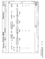
- the presently preferred embodiment provides this display in conjunction with an alphanumeric display of a program statement or expression in source code format. This is illustrated in Figure 6.
- the present information display system is thus configured to display, at the operator's request, the actual values of selected variables, simultaneously from each of the redundant computers. For added usefulness, the values are displayed along with a process control program source code statement which uses and/or calculates those variables. Preferably, the actual values of each variable in a selected source code statement are displayed immediately adjacent the display of the source code statement, as illustrated in Figure 6.
- a display window is illustrated generally at 234 . Within the display window is a child window 236 in which a source code statement appears generally at 238 . Beneath the source code statement is a display of the actual values obtained by the fox, at line 240 and the dog, at line 242 .
- analog output variable AO(123) has a value of 100 according to the fox and a value of 100 according to the dog.
- digital output variable DO(101) has a value of TRUE for both fox and dog. From a review of the example illustrated in Figure 6, one can readily discern that both fox and dog are reporting consistent values for all variables illustrated. This represents a normal operating condition where there are no discrepancies between the redundant systems, as far as the illustrated variables are concerned.
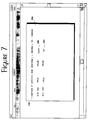
- Figure 7 illustrates the same source code listing, but with discrepancies between the fox and dog computers.
- the display window 236 may be generated for display at one or more of the workstations 28 or to any suitable display terminal connected to process information system 34 .
- the actual data values displayed in the display window may be obtained from the process control computers by strobing the data into a memory storage location (e.g., in the workstation computer) at the appropriate time.
- the data can be strobed into the operator workstation 28 via the intelligent front end 92 .
- Another way to accomplish horizontal time alignment is to fire the input data strobe after the processing interval has completed, as at point Q in Figure 5D. By firing the strobe at point Q, the input data, read from the field units, and the output data, resulting from the processing interval 228 , are from the same clock cycle. Yet another way of providing for horizontal time alignment is to fire the data acquisition strobe during the Hz' interval as at point R in Figure 5E. Firing the strobe at this point also ensures that the input and output data are from the same clock cycle.
- the system provides for vertical time alignment through the manner in which at least one of the redundant computers (the dog in the foregoing example) starts its clock cycle execution after its redundant counterpart (the fox in theforegoing example). Vertical time alignment is ensured because each of the redundant computers is responsible for reading the identical input data and, in most cases, for performing the same computational and processing steps.
- the presently preferred embodiment thus implements a loosely synchronized time alignment mechanism in which each process control computer has its own intemal clock.
- the loosely coupled synchronization technique is preferred, since it eliminates the need to rely on a single master clock which, if it were to fail, would halt the entire system. In the preferred loosely coupled synchronization scheme a failure in one of the computers' clocks would not halt the system, since the remaining redundant computer would still presumably be operative.
- Master link 60 has been illustrated by a dashed line in Figures 5A-5E. It is over this master link that the fox 220a tells the dog 220b that it has started a clock cycle, from which dog 220b is able to generate its start signal approximately 2 milliseconds thereafter. It is also over the major link 60 that the fox and dog arbitrate during the arbitration interval 226 .
- the presently preferred embodiment prepares the files needed for information display during compile time. This makes the information display system operate more quickly in use.
- the entire process control program is parsed, statement-by-statement, and an indexed file is constructed which contains not only a string describing the program statement to be displayed but also the physical location on the screen at which each of the variables associated with that statement must appear.
- the individual program statements each are assigned a unique line number which is used as the key to look up the statement in a database comprising a string or alphanumeric representation of the program statement itself, and a list of all variables which must be accessed in connection with that program statement.
- the variable list is used not only to identify which variables must be accessed for real time display but also the physical location on the screen where those variables will appear.
- a record of each variable is provided together with a list of all line numbers in which that variable appears.
- the data may be readily accessed by either direct entry of a line number or by requesting asearch of all line numbers in which the desired variable appears. In either case, the line number is used as the key by which the desired information is looked up.
- a program statement or expression is used to instruct the process control computer to perform a specific activity.
- the result of the specified activity may be internal to the process control computer, such as changing a value in memory, or extemal, such as activating an alarm, displaying a message or changing a valve position.
- a complete process control program will include a plurality of such program statements.
- Each program statement consists of a string of alphanumeric characters in one or more lines. More specifically, the alphanumeric characters are grouped into sequences called tokens.
- the tokens are the basic lexical units of the language. In other words, the token is the smallest language unit which conveys meaning.
- tokens include keywords such as the keyword IF; variable names such as Dl(101) and AO(112); constant names such as AK(100) and DK(101); variable names such as AC(12) and DC(22); operators such as LT( ⁇ ); and punctuation such as ().
- Each program statement in the presently preferred language represents a single value or causes a specific result to occur. For example, the calculation of a variable, a TRUE/FALSE digital value, a print message and an alarm are all results which have unique values as determined by a program statement.
- Each program statement or expression itself can be broken down into a left-hand side (sometimes called the L value or LVAL) and a right-hand side (sometimes called the R value or RVAL), with an "equivalence token" separating the two.
- the left-hand side represents the "resultant" of the program statement.
- the right-hand side may contain operators (such as +, -, OR, AND, XOR, ⁇ , >, etc) and operands (such as variables or constants) which determine the state of the resultant.
- operators such as +, -, OR, AND, XOR, ⁇ , >, etc
- operands such as variables or constants
- Figure 8 depicts the component parts of a program statement.
- evaluation of arithmetic expressions in the present language is accomplished by working left to right, evaluating pairs of terms using whatever arithmetic operator occurs between the pairs. As each pair is evaluated, the result becomes the first term of a pair along with the next term in the expression. If one of the terms is in brackets, the bracketed term is evaluated first in the same left to right order within the brackets.
- the presently preferred process control computer executes once each second all program statements which comprise that computer's assigned process control tasks.
- the presently preferred programming language is structured to integrate with that once-per-second cycle.
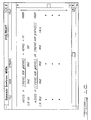
- the presently preferred program structure is illustrated at 304 .
- the program structure includes a header section designated Title 306 in which the title, author and pertinent version control information can be placed.
- the 1 cycle per second program statement section 310 also referred to as HZ1. It is this 1 Hertz section that is referenced in the 1 Hertz cycle illustrated in Figure 4.
- the 1 Hertz section 310 indudes a data input section 312 which is associated with some aspects of datacollection in the time interval 224 in Figure 4.
- the program structure also indudes a communications section 314 which is associated with communications performed in time intervals 226 and 232 .
- the 1 Hertz section indudes the sequence portion 316 in which the actual process control steps are set forth as a collection of separately identified, sequentially performable sequences. The use of sequences in the preferred embodiment is discussed more fully below.
- the end of the sequence section 316 also marks the end of the 1 Hertz section 310 .
- the 1 Hertz (1 cycle per second) time interval is used in the presently preferred embodiment, since most processes under control react slowly enough that adequate control is maintained with a 1 cycle per second control interval.
- the invention implements a 10 times per second or 10 Hertz time interval, and a 100 times per second or 100 Hertz interval.
- sections are reserved for the 10 Hertz and 100 Hertz control information. These are designated HZ10 and HZ100 and also by reference numerals 318 and 320 , respectively.
- any time remaining which is not used by the process control steps is reserved for the HZ' time interval 232 of Figure 4.
- the program structure 304 includes a space for listing any HZ' operations at 322 .
- the program structure contemplates breaking a process control problem down into a series of sequences.
- two sequences SEQ(jj) and SEQ(qq) were illustrated.
- the use of sequences can make the process control program easier to read and easier to manage and maintain.
- the decision on how to break up a process control problem into sequences is made by the process control engineer responsible for writing the program.
- the following general guidelines may be applied when a process control task is being divided into sequences:
- each sequence can be further broken down into smaller segments of operation called steps.
- Each step within a sequence indicates a particular function of the process under control.
- Each step describes what is happening in the given sequence.
- Specific process events preferably determine the beginning and end of each step. When the events which characterize a step are completed, the sequence status changes by moving to another step. Thus steps can be used to coordinate nearly all control actions and alarms for a given process.
- the presently preferred embodiment uses unique step numbers to differentiate one step from another. For example, the presently preferred embodiment has 1,000 steps available for use in the system. Steps are assigned uniquely for each sequence without overlap. Thus, if sequence 2 contains steps 200 through 215 , sequence 3 could start with step 216 and would contain none of the step numbers assigned to sequence 2.
- Sequence numbering and step numbering enable the programmer to uniquely identify a particular range of program statements or expressions.
- the specific storage location and identifiers for all available steps and all available sequences are predefined by the process control computer architecture. Being preassigned, all redundant process control computers in a system are able to make reference to the same sequence number and step number (during arbitration, for example) without ambiguity. This offers a considerable advantage in terms of speed and reliability.
- the preallocated numbering scheme ensures that all process control computers can reference a sequence number or step number without the need to perform intermediary look-up operations.
- the approach is also highly reliable since there is not ambiguity from one process control computer to another. In other words, sequence 2, step 202 refers to precisely the same sequence and step, regardless of which process control computer is making reference to it.
- an intelligent advisory system works in conjunction with the program statement display. More specifically, the advisory system is implemented in a window such as window 352 .
- the advisory window provides atextual representation of all possible states of the displayed digital variables [e,g. Dl(100)], Boolean expressions [e.g. Al(100) > Al(200)] and Boolean functions [e.g. functions to perform deviations or to time delayed events] that could make the Boolean portion of the program statement TRUE.
- This information is used to advise the system operator of ways to manipulate the variables referenced in a selected statement, in order to force the logical portion of the statement to evaluate to a TRUE state.
- the analysis that the application performs and the resulting device is based on a snapshot of the live data obtained using the above-described time-aligned data access mechanism.
- the advisory system as shown in Figure 10 may employ an expert system having a callable interface and an associated collection of "operator advice" text for display upon identification of a situation.
- the presently preferred system includes a self-evaluation option which is used to assist the operator with the interpretation of program statements.
- This option can be enabled by moving the cursor to a self-evaluation check box and dicking a mouse button. After the self-evaluation option is enabled in this fashion, all program statements shown in the main window will have the self-evaluation operation performed.
- Self-evaluation causes the display of two types of indicators for all program statements that contain Boolean expressions.
- these indicators include showing values which are currently TRUE in reverse video and by further showing how far truth has progressed through the statement using underlining.
- Figure 11 An example of how these rules are applied is shown in Figure 11.
- Figure 11 the reverse video format is depicted as a box.
- other visual attributes may be used, e.g., color change, color shading change, etc.
- the information display system includes a watch window which allows the operator to select a subset of the program statements that are currently displayed on the main window and have them displayed in a separate window called the watch window. This capability allows the operator to reconfigure the main window, to examine other items of interest, while maintaining a view of important program statements that were displayed in the original main window.
- the watch window 360 is related to the main window 234 . If desired, the watch window can be implemented as a child window of the main window. If the main window is iconized or deleted, the associated watch window will also be iconized or deleted.
- the watch window further provides a way for the operator to access the advice for TRUE function described above. If desired, there can be several watch windows associated with a single main window.
- the information display system collects live data from the redundant process control computers at a preselected time during the loosely synchronized program cycle.
- This may be implemented in a number of ways.
- the presently preferred embodiment utilizes the circuitry of the intelligent front end 92 ( Figure 2) for storing the values from each of the redundant process control computers for later access by the operator station 28 or process information system 34 .
- live data is collectedfrom the process control computers only on an as-needed basis. In other words, if a single program statement being displayed utilizes only three variables, then only those three variables are collected from the redundant process control computers.
- the presently preferred embodiment implements this by sending data request messages via the intelligent front end 92 which correspond to the variables contained in the program statement displayed in the main window (and also in any child windows or watch windows). As long as the program statement being displayed is unchanged, these data are updated each cycle and ultimately displayed beneath their alphanumeric designation in the main window. If a different program statement is selected by the operator, requiring new variables to be fetched, additional data request messages are sent via the intelligent front end 92 .
- the presently preferred embodiment synchronously sends and receives data request messages. This is preferred over asynchronous data requests since synchronous messaging does not require keeping track individually of each message sent and watching for the return of all of them before redisplaying the data.
- the live data refresh system may be automatically disabled when windows are reduced to an icon or when they are occluded by other windows.
- the incoming data is buffered using a buffering system which automatically rebuilds the buffer upon reselection of the program statement.
- the main window provides access to various options that allow the user to present information in different formats and to access other components of the invention such as the advice for TRUE component.
- the main window component is crafted to provide a mechanism for operators to access the illustrated options in the same way that other operator station features are accessed. In this way, a consistent interface is presented, making it easier for the user to work with the system intuitively.
- the graphical display window can optionally provide a graphical rendering of a program statement resembling an interconnection of pipes and valves to give the operator a concrete illustration of the flow of truth through the program statement.
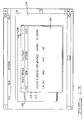
- the initialization section 364 contains the program code required to initialize the process control computer variables and peripherals such as printers, records and the like.
- the initialization section 364 does not ordinarily contain any executable code.
- the 1 Hertz section 366 references all program code that must be executed at least once per second. As explained above, this is ordinarily the place where all process control statements are placed.
- the 1 Hertz section includes input section 368 which contains references for the program code that performs data acquisition and related preprocessing, such as reading analog and digital inputs, performing digital filtering and scaling analog values.
- the 1 Hertz section also has a communications section 370 which contains references for the program code necessary to implement communication between the redundant process control computers.
- the 1 Hertz section also includes a sequence section 372 . There is one sequence section for each active sequence, with each sequence section containing references for the program code for that specific sequence. The present implementation allows a maximum of 99 sequences which may be controlled by a single program.
- the present implementation also includes a 10 Hertz section 374 and a 100 Hertz section 376 .
- the 10 Hertz section is used to contain references for program code that must be executed at least 10 times per second, while the 100 Hertz section contains references for program code that must be executed at least 100 times per second.
- the implementation includes the Hz' section 378 . This section contains references for program code that must be executed as often as possible. As previously explained, the Hz' section utilizes whatever time remains after the 1 Hertz, 10 Hertz and 100 Hertz sections have completed their operations.
- Program lines can be in the form of process control program statement lines 382 or text lines 384 .
- a program statement 382 comprises an element of a process control program. It is used to instruct the process control computer to perform a specific activity.
- Text lines serve as documentation and are not used by the program in any way. Text lines are identified by placing a comment character "C" at a predefined location to designate that line as a text line.
- program statement lines are made up of operators and functions, depicted by block 386 and also of variables depicted by block 388 .
- the present implementation provides a full complement of arithmeticand Boolean operators as well as functions for performing specific process control tasks. Naturally, the complement of functions offered by a given implementation can be made to match the types of physical operations being controlled in the plant.
- variables which make up the program statement line comprise data structures that are all predefined and preassigned to explicit memory locations within the computer architecture. These variables may also have attributes which provide additional information about the state of a process control condition as expressed by the variable. For example, digital inputs may have an attribute of manual/automatic, which indicates whether the operator has placed a particular variable (and thus the equipment that it controls) in automatic control by the process control program. In Figure 15, these attributes are depicted generally at 390 .
- program statements into a process control program can vary depending on the implementation, the presently preferred embodiment groups program lines into paragraphs 392 , pages 394 and topics 396 , as illustrated.
- the present invention provides an information display system and a tightly integrated programming environment which is ideally suited to process control applications. Redundant process control, including active redundant control is accommodated.
- the system is designed to provide the operator with up-to-date, meaningful information in a form which can be quickly and easily grasped.
- the information display system is therefore very useful in debugging process control programs, troubleshooting intermittent and faulty systems, and simply understanding how the process is actually being controlled.
Landscapes
- Engineering & Computer Science (AREA)
- General Physics & Mathematics (AREA)
- Physics & Mathematics (AREA)
- Theoretical Computer Science (AREA)
- General Engineering & Computer Science (AREA)
- Quality & Reliability (AREA)
- Automation & Control Theory (AREA)
- Computer Hardware Design (AREA)
- Computing Systems (AREA)
- Data Mining & Analysis (AREA)
- Control By Computers (AREA)
- Hardware Redundancy (AREA)
- Multi Processors (AREA)
- Testing And Monitoring For Control Systems (AREA)
- Digital Computer Display Output (AREA)
- User Interface Of Digital Computer (AREA)
- Safety Devices In Control Systems (AREA)
Claims (37)
- Système informatisé d'affichage de contrôle de processus pour transmettre des informations à un opérateur concernant l'état d'un processus sous contrôle par au moins un ordinateur de contrôle de processus (22), caractérisé par :une pluralité d'instructions de programme représentées textuellement (238) représentant au moins une partie d'une stratégie de contrôle de processus qui est utilisée pour contrôler ledit processus ;le fait que lesdites instructions de programme comportent une pluralité d'éléments représentant des paramètres de contrôle associés au processus sous contrôle ;un moyen pour obtenir automatiquement des données depuis ledit ordinateur de contrôle de processus et pour utiliser lesdites données pour affecter aux dits éléments un état courant (240, 242) pour au moins une partie desdits éléments de paramètres de contrôle.
- Système de la revendication 1, comprenant en outre un moyen pour afficher (234) lesdits états courants de ladite partie desdits paramètres de contrôle.
- Système d'affichage de contrôle de processus informatisé selon la revendication 1, ledit système comprenant :au moins un ordinateur de contrôle de processus (22) ayant un moyen d'interface pour se relier à un point de contrôle dans le processus sous contrôle et pour surveiller un premier paramètre de contrôle associé au dit point de contrôle ;un programme de contrôle de processus fonctionnant sur ledit ordinateur de contrôle de processus, le programme ayant un moyen pour contrôler le comportement d'au moins une partie du processus sous contrôle, ledit programme de contrôle de processus étant capable d'une représentation sous la forme d'une série desdites instructions de programme ;un ordinateur d'affichage (28) relié au dit ordinateur de contrôle de processus pour afficher au moins une partie de ladite série d'instructions de programme comprenant lesdits programmes de contrôle de processus ;ledit ordinateur d'affichage (28) ayant en outre des moyens d'accès et d'affichage de données pour obtenir et afficher simultanément la première valeur de paramètre de contrôle à côté de son élément dans ladite instruction de programme, grâce à quoi l'opérateur est doté d'un moyen pour faire une association visuelle entre la première valeur de paramètre de contrôle provenant dudit ordinateur de contrôle de processus et l'instruction de programme de contrôle de processus correspondante.
- Système de la revendication 3, dans lequel ledit premier paramètre de contrôle représente des données en direct provenant dudit processus sous contrôle.
- Système de la revendication 3, dans lequel ledit ordinateur de contrôle de processus comporte un autre moyen d'interface (26) pour se relier à un second point de contrôle dans le processus sous contrôle et pour surveiller un second paramètre de contrôle associé au dit second point de contrôle.
- Système de la revendication 5, dans lequel ladite série d'instructions de programme comprend au moins un élément pour représenter ledit second paramètre ; etdans lequel ledit ordinateur d'affichage (28) comporte d'autres moyens d'accès et d'affichage de données pour obtenir et afficher simultanément la seconde valeur de paramètre à côté de son élément dans ladite instruction de programme, grâce à quoi l'opérateur est doté d'un moyen pour comparer simultanément de façon visuelle la première valeur de paramètre et la seconde valeur de paramètre provenant dudit ordinateur de contrôle de processus.
- Système selon la revendication 1 ou 3, comprenant en outre une pluralité d'ordinateurs de contrôle de processus redondants (22).
- Système de la revendication 7, comprenant en outre un moyen pour afficher lesdits états courants de ladite partie desdits paramètres de contrôle.
- Système de la revendication 7, dans lequel lesdits ordinateurs de contrôle de processus sont susceptibles de traiter des instructions de programme globalement redondantes.
- Système de la revendication 7, dans lequel lesdits ordinateurs de contrôle de processus sont susceptibles de traiter des instructions de programme globalement identiques.
- Système de la revendication 7, dans lequel lesdits ordinateurs de contrôle de processus sont synchronisés par rapport à un cycle d'horloge relatif commun.
- Système de la revendication 7, dans lequel ledit moyen pour obtenir automatiquement des données est susceptible de réaliser un alignement vertical temporel en obtenant des données depuis chacun desdits ordinateurs de contrôle de processus (22) pendant le même cycle d'horloge relatif.
- Système de la revendication 7, dans lequel lesdits ordinateurs de contrôle de processus sont chacun susceptibles de définir un cycle d'horloge et dans lequel chaque ordinateur est susceptible de traiter toutes les instructions de programme représentant ladite partie de ladite stratégie de contrôle de processus complètement pendant un seul cycle d'horloge.
- Système de la revendication 7, comprenant en outre un moyen pour établir une communication (24) entre lesdits ordinateurs de contrôle de processus, et pour utiliser ladite communication pour synchroniser lesdits ordinateurs de contrôle de processus sur un cycle d'horloge relatif commun.
- Système selon les revendications 7 et 11, dans lequel ledit moyen pour obtenir automatiquement des données est susceptible de réaliser un alignement horizontal temporel en obtenant des données pour une pluralité d'éléments différents provenant de chacun desdits ordinateurs de contrôle de processus pendant le même cycle d'horloge relatif.
- Système de la revendication 7, dans lequel chacun desdits ordinateurs de contrôle de processus est susceptible d'établir un cycle d'horloge pendant lequel la stratégie de contrôle de processus est entièrement exécutée.
- Système de la revendication 16, dans lequel ledit cycle d'horloge comprend un intervalle de temps prédéfini pendant lequel les données sont obtenues automatiquement.
- Système de la revendication 16, dans lequel lesdits ordinateurs de contrôle de processus sont susceptibles de produire au moins un signal de sortie et dans lequel ledit signal est produit pendant un intervalle de temps prédéfini dans ledit cycle d'horloge.
- Système selon la revendication 1, dans lequel ladite pluralité d'éléments comprend au moins un élément de valeur G et au moins un élément de valeur D ayant chacun une partie Booléenne ;ledit moyen pour obtenir automatiquement des données depuis ledit processus sous contrôle est susceptible d'utiliser lesdites données pour affecter aux dits éléments de valeur D un état Booléen courant pour chacun desdits éléments ;ledit système comprenant en outre un moyen pour fournir une représentation textuelle de tous les états possibles des parties Booléennes desdites valeurs D qui rendent la partie Booléenne de ladite valeur G VRAIe, grâce à quoi des informations concernant l'état de la stratégie de contrôle de processus sont transmises à l'opérateur.
- Système selon la revendication 19, comprenant en outre un moyen pour afficher ladite instruction de programme représentée textuellement en utilisant un premier attribut d'affichage pouvant être distingué visuellement pour représenter des éléments qui sont actuellement VRAIs et en utilisant un second attribut d'affichage pouvant être distingué visuellement pour représenter des éléments qui sont actuellement FAUX, grâce à quoi des informations concernant l'état de la stratégie de contrôle de processus sont transmises à l'opérateur.
- Système de la revendication 1, comprenant en outre :un moyen pour établir une fenêtre d'affichage principale (236) et une fenêtre de surveillance (360) associée à ladite fenêtre d'affichage principale pour afficher des informations représentées textuellement ;un moyen pour sélectionner un premier sous-ensemble de ladite pluralité d'instructions de programme représentées textuellement, et pour afficher ledit premier sous-ensemble dans ladite fenêtre de surveillance ;un moyen pour, sans changer le premier sous-ensemble sélectionné, sélectionner un second sous-ensemble de ladite pluralité d'instructions de programme représentées textuellement, et pour afficher ledit premier sous-ensemble dans ladite fenêtre principale ;dans lequel l'affichage dudit premier sous-ensemble dans ladite fenêtre de surveillance et l'affichage dudit second sous-ensemble dans ladite fenêtre principale sont réalisés de façon indépendante, de sorte que la sélection dudit premier sous-ensemble est inchangée par un changement dans la sélection dudit second sous-ensemble, grâce à quoi des informations concernant l'état des premier et second sous-ensembles sont transmises de façon indépendante et simultanée à l'opérateur.
- Système de la revendication 3, dans lequel chaque ordinateur de ladite pluralité d'ordinateurs de contrôle de processus comporte en outre un moyen d'interface pour connexion à un second point commun dans le processus sous contrôle, et pour surveiller un second paramètre commun associé au dit second point commun.
- Système de la revendication 22, dans lequel l'opérateur est doté d'un moyen pour comparer simultanément de façon visuelle les valeurs du premier paramètre commun et les valeurs du second paramètre commun provenant de ladite pluralité d'ordinateurs de contrôle de processus.
- Procédé informatisé d'affichage de contrôle de processus pour transmettre des informations à un opérateur concernant l'état d'un processus sous contrôle par au moins un ordinateur de contrôle de processus (22), caractérisé par le fait qu'il comprend les étapes consistant :à utiliser une pluralité d'instructions de programmes représentées textuellement (238) pour représenter au moins une partie d'une stratégie de contrôle de processus qui est utilisée pour contrôler ledit processus ;le fait que lesdites instructions de programme comprennent une pluralité d'éléments représentant des paramètres de contrôle associés au processus sous contrôle ;à obtenir automatiquement des données depuis ledit ordinateur de contrôle de processus et à utiliser lesdites données pour affecter aux dits éléments un état courant (240, 242) pour au moins une partie desdits éléments de paramètre de contrôle.
- Procédé de la revendication 24, comprenant en outre l'affichage desdits états courants de ladite partie desdits paramètres de contrôle.
- Procédé de la revendication 24, caractérisé par l'étape consistant à utiliser une pluralité d'ordinateurs de contrôle de processus redondants (22) pour contrôler l'état dudit processus.
- Procédé de la revendication 26, comprenant en outre l'affichage desdits états courants de ladite partie desdits paramètres de contrôle.
- Procédé de la revendication 26, comprenant en outre l'utilisation desdits ordinateurs de contrôle de processus pour traiter des instructions de programmes globalement redondantes.
- Procédé de la revendication 26, comprenant en outre l'utilisation desdits ordinateurs de contrôle de processus pour traiter des instructions de programmes globalement identiques.
- Procédé de la revendication 26, comprenant en outre la synchronisation desdits ordinateurs de contrôle de processus par rapport à un cycle d'horloge relatif commun.
- Procédé de la revendication 26, comprenant en outre la synchronisation desdits ordinateurs de contrôle de processus par rapport à un cycle d'horloge relatif commun, et dans lequel ladite étape consistant à obtenir automatiquement des données est exécutée pour réaliser un alignement vertical temporel en obtenant des données depuis chacun desdits ordinateurs de contrôle de processus pendant le même cycle d'horloge relatif.
- Procédé de la revendication 26, dans lequel lesdits ordinateurs de contrôle de processus définissent chacun un cycle d'horloge, et dans lequel chaque ordinateur traite toutes les instructions de programme représentant ladite partie de ladite stratégie de contrôle de processus complètement pendant un seul cycle d'horloge.
- Procédé de la revendication 26, comprenant en outre l'établissement d'une communication entre lesdits ordinateurs de contrôle de processus, et l'utilisation de ladite communication pour synchroniser lesdits ordinateurs de contrôle de processus sur un cycle d'horloge relatif commun.
- Procédé de la revendication 26, comprenant en outre la synchronisation desdits ordinateurs de contrôle de processus par rapport à un cycle d'horloge relatif commun, et dans lequel ladite étape consistant à obtenir des données automatiquement est exécutée pour réaliser un alignement horizontal temporel en obtenant des données pour une pluralité d'éléments différents depuis chacun desdits ordinateurs de contrôle de processus pendant le même cycle d'horloge relatif.
- Procédé de la revendication 26, dans lequel chacun desdits ordinateurs de contrôle de processus établit un cycle d'horloge pendant lequel la stratégie de contrôle de processus est entièrement exécutée.
- Procédé de la revendication 35, dans lequel ledit cycle d'horloge comprend un intervalle de temps prédéfini pendant lequel les données sont obtenues automatiquement.
- Procédé de la revendication 35, dans lequel lesdits ordinateurs de contrôle de processus produisent au moins un signal de sortie, et dans lequel ledit signal est produit pendant un intervalle de temps prédéfini dans ledit cycle d'horloge.
Applications Claiming Priority (3)
| Application Number | Priority Date | Filing Date | Title |
|---|---|---|---|
| US08/173,407 US5491625A (en) | 1993-12-23 | 1993-12-23 | Information display system for actively redundant computerized process control |
| US173407 | 1993-12-23 | ||
| PCT/US1994/014330 WO1995017706A2 (fr) | 1993-12-23 | 1994-12-21 | Systeme d'affichage d'informations pour commande de processus informatise a activite redondante |
Publications (2)
| Publication Number | Publication Date |
|---|---|
| EP0764294A1 EP0764294A1 (fr) | 1997-03-26 |
| EP0764294B1 true EP0764294B1 (fr) | 1998-11-11 |
Family
ID=22631867
Family Applications (1)
| Application Number | Title | Priority Date | Filing Date |
|---|---|---|---|
| EP95905916A Expired - Lifetime EP0764294B1 (fr) | 1993-12-23 | 1994-12-21 | Systeme d'affichage d'informations pour commande de processus informatise a activite redondante |
Country Status (8)
| Country | Link |
|---|---|
| US (1) | US5491625A (fr) |
| EP (1) | EP0764294B1 (fr) |
| JP (1) | JPH09509511A (fr) |
| AT (1) | ATE173344T1 (fr) |
| CA (1) | CA2179298A1 (fr) |
| DE (1) | DE69414609T2 (fr) |
| ES (1) | ES2126247T3 (fr) |
| WO (1) | WO1995017706A2 (fr) |
Families Citing this family (42)
| Publication number | Priority date | Publication date | Assignee | Title |
|---|---|---|---|---|
| US5768119A (en) * | 1996-04-12 | 1998-06-16 | Fisher-Rosemount Systems, Inc. | Process control system including alarm priority adjustment |
| JP3582230B2 (ja) * | 1996-06-04 | 2004-10-27 | 三菱電機株式会社 | 制御システム |
| EP0825506B1 (fr) * | 1996-08-20 | 2013-03-06 | Invensys Systems, Inc. | Méthodes et appareil de commande à distance de processus |
| US5790397A (en) | 1996-09-17 | 1998-08-04 | Marathon Technologies Corporation | Fault resilient/fault tolerant computing |
| US5790437A (en) * | 1996-11-26 | 1998-08-04 | Watlow Electric Manufacturing Company | Graphical interface for programming ramping controllers |
| DE19718284C2 (de) * | 1997-05-01 | 2001-09-27 | Kuka Roboter Gmbh | Verfahren und Vorrichtung zum Überwachen einer Anlage mit mehreren Funktionseinheiten |
| US6748451B2 (en) | 1998-05-26 | 2004-06-08 | Dow Global Technologies Inc. | Distributed computing environment using real-time scheduling logic and time deterministic architecture |
| AT412131B (de) * | 1998-11-24 | 2004-09-27 | Automationx Software For Ind A | Automatisierungssystem zur lösung einer prozesstechnischen aufgabenstellung und verfahren hierzu |
| US6367031B1 (en) | 1998-12-17 | 2002-04-02 | Honeywell International Inc. | Critical control adaption of integrated modular architecture |
| US6647301B1 (en) * | 1999-04-22 | 2003-11-11 | Dow Global Technologies Inc. | Process control system with integrated safety control system |
| DE19918270A1 (de) * | 1999-04-22 | 2000-10-26 | Abb Patent Gmbh | Verfahren zur bedarfsabhängigen Berechnung einer Funktion |
| US7089530B1 (en) * | 1999-05-17 | 2006-08-08 | Invensys Systems, Inc. | Process control configuration system with connection validation and configuration |
| WO2000070417A1 (fr) * | 1999-05-17 | 2000-11-23 | The Foxboro Company | Systeme de configuration de commande de processus via des objets parametres |
| US6788980B1 (en) * | 1999-06-11 | 2004-09-07 | Invensys Systems, Inc. | Methods and apparatus for control using control devices that provide a virtual machine environment and that communicate via an IP network |
| DE19947065A1 (de) * | 1999-09-30 | 2001-04-05 | Siemens Ag | Darstellung von hochbitratigen Daten |
| US6473660B1 (en) * | 1999-12-03 | 2002-10-29 | The Foxboro Company | Process control system and method with automatic fault avoidance |
| FR2838532B1 (fr) * | 2002-04-10 | 2004-07-30 | Airbus France | Systeme et procede de controle de plusieurs actionneurs |
| US20040034440A1 (en) * | 2002-08-14 | 2004-02-19 | Richard Middlebrook | Golf handicap and merchandising kiosk |
| DE10348563B4 (de) | 2002-10-22 | 2014-01-09 | Fisher-Rosemount Systems, Inc. | Integration von Grafikdisplayelementen, Prozeßmodulen und Steuermodulen in Prozeßanlagen |
| US9983559B2 (en) * | 2002-10-22 | 2018-05-29 | Fisher-Rosemount Systems, Inc. | Updating and utilizing dynamic process simulation in an operating process environment |
| US6813527B2 (en) * | 2002-11-20 | 2004-11-02 | Honeywell International Inc. | High integrity control system architecture using digital computing platforms with rapid recovery |
| US7761923B2 (en) * | 2004-03-01 | 2010-07-20 | Invensys Systems, Inc. | Process control methods and apparatus for intrusion detection, protection and network hardening |
| US7680970B2 (en) * | 2004-10-22 | 2010-03-16 | Fisher-Rosemount Systems, Inc. | Method and system for batch process arbitration in a process control system |
| US20060155770A1 (en) * | 2004-11-11 | 2006-07-13 | Ipdev Co. | System and method for time-based allocation of unique transaction identifiers in a multi-server system |
| US20060155753A1 (en) * | 2004-11-11 | 2006-07-13 | Marc Asher | Global asynchronous serialized transaction identifier |
| US20060123098A1 (en) * | 2004-11-11 | 2006-06-08 | Ipdev | Multi-system auto-failure web-based system with dynamic session recovery |
| DE102005036475B3 (de) * | 2005-08-03 | 2007-04-12 | Kress, Wolfram | Verfahren zur sicheren Bedienung und Programmierung sicherheitsgerichteter Geräte |
| SE529676C2 (sv) * | 2006-03-02 | 2007-10-23 | Abb Ab | En metod för att utvärdera en applikation, ett automationssystem och en styrenhet |
| SE529634C2 (sv) * | 2006-03-02 | 2007-10-09 | Abb Ab | En metod för att jämföra variabelvärden erhållna från olika versioner av ett applikationsprogram samt ett automationssystem och en styrenhet |
| WO2007123753A2 (fr) * | 2006-03-30 | 2007-11-01 | Invensys Systems, Inc. | Dispositif et procédés de traitement de données numériques et d'optimisation des performances d'une installation |
| US20080189718A1 (en) * | 2007-02-02 | 2008-08-07 | The Mathworks, Inc. | Scalable architecture |
| US20090076628A1 (en) * | 2007-09-18 | 2009-03-19 | David Mark Smith | Methods and apparatus to upgrade and provide control redundancy in process plants |
| CN104407518B (zh) | 2008-06-20 | 2017-05-31 | 因文西斯系统公司 | 对用于过程控制的实际和仿真设施进行交互的系统和方法 |
| US8127060B2 (en) | 2009-05-29 | 2012-02-28 | Invensys Systems, Inc | Methods and apparatus for control configuration with control objects that are fieldbus protocol-aware |
| US8463964B2 (en) * | 2009-05-29 | 2013-06-11 | Invensys Systems, Inc. | Methods and apparatus for control configuration with enhanced change-tracking |
| EP2309354B1 (fr) * | 2009-10-01 | 2013-03-20 | Siemens Aktiengesellschaft | Dispositif et procédé destinés à la simulation |
| EP2811354A1 (fr) * | 2013-06-03 | 2014-12-10 | Siemens Aktiengesellschaft | Système d'automatisation de processus avec une unité de calcul centrale |
| CN104049621B (zh) * | 2014-07-03 | 2016-09-28 | 中南大学 | 一种基于上位机和可编程控制器的系统辨识方法 |
| JP6407919B2 (ja) * | 2016-06-15 | 2018-10-17 | ファナック株式会社 | 数値制御装置および変数判定方法 |
| US10878140B2 (en) | 2016-07-27 | 2020-12-29 | Emerson Process Management Power & Water Solutions, Inc. | Plant builder system with integrated simulation and control system configuration |
| US11418969B2 (en) | 2021-01-15 | 2022-08-16 | Fisher-Rosemount Systems, Inc. | Suggestive device connectivity planning |
| JP2022185722A (ja) * | 2021-06-03 | 2022-12-15 | キヤノン株式会社 | 基板処理システムおよびその制御方法 |
Family Cites Families (9)
| Publication number | Priority date | Publication date | Assignee | Title |
|---|---|---|---|---|
| US4500951A (en) * | 1981-01-07 | 1985-02-19 | Hitachi, Ltd. | Plant control system |
| DE3225455C2 (de) * | 1982-07-07 | 1986-07-17 | Siemens AG, 1000 Berlin und 8000 München | Verfahren zum sicheren Betrieb eines redundanten Steuersystems |
| US4562529A (en) * | 1982-09-01 | 1985-12-31 | Programasyst Limited | Control of real time industrial processes |
| US4641269A (en) * | 1983-01-26 | 1987-02-03 | Emhart Industries, Inc. | Programmable control system for glassware forming machines |
| US5157595A (en) * | 1985-07-19 | 1992-10-20 | El Paso Technologies, Company | Distributed logic control system and method |
| US5400246A (en) * | 1989-05-09 | 1995-03-21 | Ansan Industries, Ltd. | Peripheral data acquisition, monitor, and adaptive control system via personal computer |
| US5162986A (en) * | 1990-10-19 | 1992-11-10 | Allen-Bradley Company, Inc. | Remote downloading and uploading of motion control program information to and from a motion control I/O module in a programmable controller |
| US5301100A (en) * | 1991-04-29 | 1994-04-05 | Wagner Ferdinand H | Method of and apparatus for constructing a control system and control system created thereby |
| US5265004A (en) * | 1991-10-15 | 1993-11-23 | Allen-Bradley Company, Inc. | Sequence controller with combinatorial Boolean logic |
-
1993
- 1993-12-23 US US08/173,407 patent/US5491625A/en not_active Expired - Fee Related
-
1994
- 1994-12-21 AT AT95905916T patent/ATE173344T1/de not_active IP Right Cessation
- 1994-12-21 ES ES95905916T patent/ES2126247T3/es not_active Expired - Lifetime
- 1994-12-21 DE DE69414609T patent/DE69414609T2/de not_active Expired - Fee Related
- 1994-12-21 JP JP7517486A patent/JPH09509511A/ja not_active Ceased
- 1994-12-21 WO PCT/US1994/014330 patent/WO1995017706A2/fr not_active Ceased
- 1994-12-21 EP EP95905916A patent/EP0764294B1/fr not_active Expired - Lifetime
- 1994-12-21 CA CA002179298A patent/CA2179298A1/fr not_active Abandoned
Also Published As
| Publication number | Publication date |
|---|---|
| DE69414609D1 (de) | 1998-12-17 |
| CA2179298A1 (fr) | 1995-06-29 |
| US5491625A (en) | 1996-02-13 |
| JPH09509511A (ja) | 1997-09-22 |
| EP0764294A1 (fr) | 1997-03-26 |
| ES2126247T3 (es) | 1999-03-16 |
| DE69414609T2 (de) | 1999-07-22 |
| WO1995017706A2 (fr) | 1995-06-29 |
| ATE173344T1 (de) | 1998-11-15 |
| WO1995017706A3 (fr) | 1997-02-13 |
Similar Documents
| Publication | Publication Date | Title |
|---|---|---|
| EP0764294B1 (fr) | Systeme d'affichage d'informations pour commande de processus informatise a activite redondante | |
| WO1995017706A9 (fr) | Systeme d'affichage d'informations pour commande de processus informatise a activite redondante | |
| US5933655A (en) | System for scheduling periodic events having varying rates by cascading a plurality of overlapping linked list data structure | |
| US5325522A (en) | Apparatus and method for communicating between devices trough use of a real time data base | |
| CN101460909B (zh) | 系统管理人机界面 | |
| US8321790B2 (en) | System management user interface providing user access to status information for process control system equipment including a search function | |
| Benveniste et al. | Diagnosis of asynchronous discrete-event systems: a net unfolding approach | |
| US4855906A (en) | System for handling unsolicited messages from lower-tier controllers | |
| US5801942A (en) | Process control system user interface including selection of multiple control languages | |
| US7275236B1 (en) | Method for programming a multiple device control system using object sharing | |
| US5023832A (en) | Method of maintaining asynchronous real-time data | |
| US7729887B2 (en) | System management user interface providing user access to status information for process control system equipment including a status monitor | |
| US5386503A (en) | Method for controlling window displays in an open systems windows environment | |
| US7729886B2 (en) | System management user interface providing user access to status information for process control system equipment | |
| US5564049A (en) | Industrial controller programming method using external connection database | |
| US5712974A (en) | Method and apparatus for controlling the configuration definitions in a data processing system with a plurality of processors | |
| CA1183609A (fr) | Interface homme-machine | |
| WO2007121212A2 (fr) | Interface homme-machine de gestion de systeme | |
| Holt et al. | An architecture for real-time distributed artificial intelligent systems | |
| CN1040588C (zh) | 适用于实现顺序控制和伺服控制的计算机控制系统和方法 | |
| Corsberg et al. | A nuclear reactor alarm display system utilizing AI techniques for alarm filtering | |
| JP3813756B2 (ja) | プログラマブルコントローラ | |
| JP3601061B2 (ja) | 生産設備の情報処理装置 | |
| Kalogeras et al. | Presentation of a new Local Area Network for CIM applications | |
| Decotignie et al. | Field Buses in Manufacturing Automation: A Study of the Application Layer Requirements |
Legal Events
| Date | Code | Title | Description |
|---|---|---|---|
| PUAI | Public reference made under article 153(3) epc to a published international application that has entered the european phase |
Free format text: ORIGINAL CODE: 0009012 |
|
| 17P | Request for examination filed |
Effective date: 19960719 |
|
| AK | Designated contracting states |
Kind code of ref document: A1 Designated state(s): AT BE CH DE DK ES FR GB GR IE IT LI LU MC NL PT SE |
|
| 17Q | First examination report despatched |
Effective date: 19970611 |
|
| RAP3 | Party data changed (applicant data changed or rights of an application transferred) |
Owner name: THE DOW CHEMICAL COMPANY |
|
| GRAG | Despatch of communication of intention to grant |
Free format text: ORIGINAL CODE: EPIDOS AGRA |
|
| GRAG | Despatch of communication of intention to grant |
Free format text: ORIGINAL CODE: EPIDOS AGRA |
|
| GRAH | Despatch of communication of intention to grant a patent |
Free format text: ORIGINAL CODE: EPIDOS IGRA |
|
| GRAH | Despatch of communication of intention to grant a patent |
Free format text: ORIGINAL CODE: EPIDOS IGRA |
|
| GRAA | (expected) grant |
Free format text: ORIGINAL CODE: 0009210 |
|
| AK | Designated contracting states |
Kind code of ref document: B1 Designated state(s): AT BE CH DE DK ES FR GB GR IE IT LI LU MC NL PT SE |
|
| PG25 | Lapsed in a contracting state [announced via postgrant information from national office to epo] |
Ref country code: SE Free format text: THE PATENT HAS BEEN ANNULLED BY A DECISION OF A NATIONAL AUTHORITY Effective date: 19981111 Ref country code: LI Free format text: LAPSE BECAUSE OF FAILURE TO SUBMIT A TRANSLATION OF THE DESCRIPTION OR TO PAY THE FEE WITHIN THE PRESCRIBED TIME-LIMIT Effective date: 19981111 Ref country code: GR Free format text: LAPSE BECAUSE OF NON-PAYMENT OF DUE FEES Effective date: 19981111 Ref country code: CH Free format text: LAPSE BECAUSE OF FAILURE TO SUBMIT A TRANSLATION OF THE DESCRIPTION OR TO PAY THE FEE WITHIN THE PRESCRIBED TIME-LIMIT Effective date: 19981111 Ref country code: AT Free format text: LAPSE BECAUSE OF FAILURE TO SUBMIT A TRANSLATION OF THE DESCRIPTION OR TO PAY THE FEE WITHIN THE PRESCRIBED TIME-LIMIT Effective date: 19981111 |
|
| REF | Corresponds to: |
Ref document number: 173344 Country of ref document: AT Date of ref document: 19981115 Kind code of ref document: T |
|
| REG | Reference to a national code |
Ref country code: CH Ref legal event code: EP |
|
| REF | Corresponds to: |
Ref document number: 69414609 Country of ref document: DE Date of ref document: 19981217 |
|
| PG25 | Lapsed in a contracting state [announced via postgrant information from national office to epo] |
Ref country code: LU Free format text: LAPSE BECAUSE OF NON-PAYMENT OF DUE FEES Effective date: 19981221 |
|
| PG25 | Lapsed in a contracting state [announced via postgrant information from national office to epo] |
Ref country code: IE Free format text: LAPSE BECAUSE OF NON-PAYMENT OF DUE FEES Effective date: 19990111 |
|
| REG | Reference to a national code |
Ref country code: IE Ref legal event code: FG4D |
|
| ET | Fr: translation filed | ||
| PG25 | Lapsed in a contracting state [announced via postgrant information from national office to epo] |
Ref country code: PT Free format text: LAPSE BECAUSE OF FAILURE TO SUBMIT A TRANSLATION OF THE DESCRIPTION OR TO PAY THE FEE WITHIN THE PRESCRIBED TIME-LIMIT Effective date: 19990211 Ref country code: DK Free format text: LAPSE BECAUSE OF FAILURE TO SUBMIT A TRANSLATION OF THE DESCRIPTION OR TO PAY THE FEE WITHIN THE PRESCRIBED TIME-LIMIT Effective date: 19990211 |
|
| REG | Reference to a national code |
Ref country code: ES Ref legal event code: FG2A Ref document number: 2126247 Country of ref document: ES Kind code of ref document: T3 |
|
| REG | Reference to a national code |
Ref country code: CH Ref legal event code: PL |
|
| PG25 | Lapsed in a contracting state [announced via postgrant information from national office to epo] |
Ref country code: MC Free format text: LAPSE BECAUSE OF NON-PAYMENT OF DUE FEES Effective date: 19990630 |
|
| PLBE | No opposition filed within time limit |
Free format text: ORIGINAL CODE: 0009261 |
|
| STAA | Information on the status of an ep patent application or granted ep patent |
Free format text: STATUS: NO OPPOSITION FILED WITHIN TIME LIMIT |
|
| 26N | No opposition filed | ||
| REG | Reference to a national code |
Ref country code: IE Ref legal event code: MM4A |
|
| REG | Reference to a national code |
Ref country code: GB Ref legal event code: IF02 |
|
| PGFP | Annual fee paid to national office [announced via postgrant information from national office to epo] |
Ref country code: FR Payment date: 20020905 Year of fee payment: 9 |
|
| PGFP | Annual fee paid to national office [announced via postgrant information from national office to epo] |
Ref country code: NL Payment date: 20020910 Year of fee payment: 9 |
|
| PGFP | Annual fee paid to national office [announced via postgrant information from national office to epo] |
Ref country code: GB Payment date: 20020923 Year of fee payment: 9 |
|
| PGFP | Annual fee paid to national office [announced via postgrant information from national office to epo] |
Ref country code: BE Payment date: 20021023 Year of fee payment: 9 |
|
| PGFP | Annual fee paid to national office [announced via postgrant information from national office to epo] |
Ref country code: DE Payment date: 20021101 Year of fee payment: 9 |
|
| PGFP | Annual fee paid to national office [announced via postgrant information from national office to epo] |
Ref country code: ES Payment date: 20021204 Year of fee payment: 9 |
|
| PG25 | Lapsed in a contracting state [announced via postgrant information from national office to epo] |
Ref country code: GB Free format text: LAPSE BECAUSE OF NON-PAYMENT OF DUE FEES Effective date: 20031221 |
|
| PG25 | Lapsed in a contracting state [announced via postgrant information from national office to epo] |
Ref country code: ES Free format text: LAPSE BECAUSE OF NON-PAYMENT OF DUE FEES Effective date: 20031222 |
|
| PG25 | Lapsed in a contracting state [announced via postgrant information from national office to epo] |
Ref country code: BE Free format text: LAPSE BECAUSE OF NON-PAYMENT OF DUE FEES Effective date: 20031231 |
|
| BERE | Be: lapsed |
Owner name: THE *DOW CHEMICAL CY Effective date: 20031231 |
|
| PG25 | Lapsed in a contracting state [announced via postgrant information from national office to epo] |
Ref country code: NL Free format text: LAPSE BECAUSE OF NON-PAYMENT OF DUE FEES Effective date: 20040701 Ref country code: DE Free format text: LAPSE BECAUSE OF NON-PAYMENT OF DUE FEES Effective date: 20040701 |
|
| GBPC | Gb: european patent ceased through non-payment of renewal fee |
Effective date: 20031221 |
|
| PG25 | Lapsed in a contracting state [announced via postgrant information from national office to epo] |
Ref country code: FR Free format text: LAPSE BECAUSE OF NON-PAYMENT OF DUE FEES Effective date: 20040831 |
|
| NLV4 | Nl: lapsed or anulled due to non-payment of the annual fee |
Effective date: 20040701 |
|
| REG | Reference to a national code |
Ref country code: FR Ref legal event code: ST |
|
| REG | Reference to a national code |
Ref country code: ES Ref legal event code: FD2A Effective date: 20031222 |
|
| PG25 | Lapsed in a contracting state [announced via postgrant information from national office to epo] |
Ref country code: IT Free format text: LAPSE BECAUSE OF NON-PAYMENT OF DUE FEES;WARNING: LAPSES OF ITALIAN PATENTS WITH EFFECTIVE DATE BEFORE 2007 MAY HAVE OCCURRED AT ANY TIME BEFORE 2007. THE CORRECT EFFECTIVE DATE MAY BE DIFFERENT FROM THE ONE RECORDED. Effective date: 20051221 |