EP0772806B1 - Systeme de transport - Google Patents
Systeme de transport Download PDFInfo
- Publication number
- EP0772806B1 EP0772806B1 EP95907088A EP95907088A EP0772806B1 EP 0772806 B1 EP0772806 B1 EP 0772806B1 EP 95907088 A EP95907088 A EP 95907088A EP 95907088 A EP95907088 A EP 95907088A EP 0772806 B1 EP0772806 B1 EP 0772806B1
- Authority
- EP
- European Patent Office
- Prior art keywords
- road
- vehicle
- data
- control
- operative
- Prior art date
- Legal status (The legal status is an assumption and is not a legal conclusion. Google has not performed a legal analysis and makes no representation as to the accuracy of the status listed.)
- Expired - Lifetime
Links
- 230000006854 communication Effects 0.000 claims abstract description 126
- 238000004891 communication Methods 0.000 claims abstract description 126
- 238000012545 processing Methods 0.000 claims abstract description 34
- 230000004044 response Effects 0.000 claims abstract description 32
- 230000006870 function Effects 0.000 claims abstract description 18
- 230000005540 biological transmission Effects 0.000 claims description 73
- 238000000034 method Methods 0.000 claims description 37
- 238000011144 upstream manufacturing Methods 0.000 claims description 13
- 238000010276 construction Methods 0.000 claims description 7
- 238000001514 detection method Methods 0.000 claims description 6
- 230000008569 process Effects 0.000 claims description 6
- 238000011156 evaluation Methods 0.000 claims description 4
- 238000010586 diagram Methods 0.000 description 8
- 230000008859 change Effects 0.000 description 7
- 238000012790 confirmation Methods 0.000 description 5
- 238000013479 data entry Methods 0.000 description 5
- 238000012546 transfer Methods 0.000 description 5
- 230000000007 visual effect Effects 0.000 description 5
- 238000007726 management method Methods 0.000 description 4
- 238000005259 measurement Methods 0.000 description 4
- 230000001960 triggered effect Effects 0.000 description 4
- 230000009471 action Effects 0.000 description 2
- 239000000470 constituent Substances 0.000 description 2
- 230000000694 effects Effects 0.000 description 2
- 239000000446 fuel Substances 0.000 description 2
- 230000000977 initiatory effect Effects 0.000 description 2
- 238000013439 planning Methods 0.000 description 2
- 230000001133 acceleration Effects 0.000 description 1
- 230000004913 activation Effects 0.000 description 1
- 230000032683 aging Effects 0.000 description 1
- 239000010426 asphalt Substances 0.000 description 1
- 230000006399 behavior Effects 0.000 description 1
- 230000007175 bidirectional communication Effects 0.000 description 1
- 238000012937 correction Methods 0.000 description 1
- 230000000881 depressing effect Effects 0.000 description 1
- 238000011161 development Methods 0.000 description 1
- 230000018109 developmental process Effects 0.000 description 1
- 238000009434 installation Methods 0.000 description 1
- 230000003993 interaction Effects 0.000 description 1
- 230000002045 lasting effect Effects 0.000 description 1
- 238000012423 maintenance Methods 0.000 description 1
- 230000007257 malfunction Effects 0.000 description 1
- 238000004519 manufacturing process Methods 0.000 description 1
- 230000035484 reaction time Effects 0.000 description 1
- 230000011514 reflex Effects 0.000 description 1
- 230000000717 retained effect Effects 0.000 description 1
- 230000001953 sensory effect Effects 0.000 description 1
- 230000037152 sensory function Effects 0.000 description 1
- 230000003867 tiredness Effects 0.000 description 1
- 208000016255 tiredness Diseases 0.000 description 1
- 238000012384 transportation and delivery Methods 0.000 description 1
Images


Classifications
-
- G—PHYSICS
- G05—CONTROLLING; REGULATING
- G05D—SYSTEMS FOR CONTROLLING OR REGULATING NON-ELECTRIC VARIABLES
- G05D1/00—Control of position, course, altitude or attitude of land, water, air or space vehicles, e.g. using automatic pilots
- G05D1/02—Control of position or course in two dimensions
- G05D1/021—Control of position or course in two dimensions specially adapted to land vehicles
- G05D1/0259—Control of position or course in two dimensions specially adapted to land vehicles using magnetic or electromagnetic means
- G05D1/0265—Control of position or course in two dimensions specially adapted to land vehicles using magnetic or electromagnetic means using buried wires
-
- G—PHYSICS
- G05—CONTROLLING; REGULATING
- G05D—SYSTEMS FOR CONTROLLING OR REGULATING NON-ELECTRIC VARIABLES
- G05D1/00—Control of position, course, altitude or attitude of land, water, air or space vehicles, e.g. using automatic pilots
- G05D1/02—Control of position or course in two dimensions
- G05D1/021—Control of position or course in two dimensions specially adapted to land vehicles
- G05D1/0287—Control of position or course in two dimensions specially adapted to land vehicles involving a plurality of land vehicles, e.g. fleet or convoy travelling
- G05D1/0291—Fleet control
- G05D1/0293—Convoy travelling
Definitions
- the present invention relates to automated transport systems in general, and, in particular, to automated road vehicle transport systems.
- a further transport-related problem is that of loss of time which may be caused by slow driving speed due to weather conditions, road conditions, visibility, and traffic congestion, for example. Unfamiliarity with the route may also cause a loss of time.
- Redundant measurement capability comprising inputs from linear travel encoders from the vehicle's drive wheels, position measurements from update markers, and bearing measurements from a novel angular sensing apparatus, in combination with the use of a Kalman filter, allows correction for navigation and guidance errors caused by such factors as angular rate sensor drift, wear, temperature changes, aging, and early miscalibration during vehicle operation.
- the control system comprises high frequency two-way data transmission and reception capability over the guidewires and via wireless communications. The same data rates and message formats are used in both communications systems.
- the above-outlined system is intended for purpose-built vehicles used in a warehouse situation. Accordingly, while addressing certain points of automated control of vehicles, it does not provide a solution to the various transport related problems discussed herein.
- EP482424, EP229669, WO8200122 and EP367527 These publications describe systems that are intended for controlling vehicles in limited, defined areas, such as on factory floors, in the area of production lines, warehouses and the like. These systems include several dozen vehicles that travel in predetermined fashion along fixed routes, with fixed stopping places or stations, and which travel over a distance of between several dozen meters and several kilometers.
- USP 4361202 describes a transport system that may contain millions of vehicles, but it is based on a single central computer, with its inherent drawbacks, as discussed above. Furthermore, no continuous communications exist between this system and the vehicles 'controlled' thereby.
- System to vehicle communications are established at commencement of a journey only, by means of a radio-telephone link to the control center operated by a vehicle driver, so as to receive details of a recommended route, including driving directions that are recorded in the memory of a computer in the vehicle. Subsequently, unless the driver initiates further communication with the control center, no communications occur until the end of the journey.
- the vehicle drives itself in accordance with the route plan stored in its computer memory, and, further, in accordance with information provided by transponders along the route that provide to the vehicle information concerning the conditions and physical parameters at the transponder locations, rather than information particular to any specific vehicle traveling therepast.
- This operating principle is based on the assumption that no changes will occur (or be required) and that the transport system will behave in practice exactly as planned - an assumption which, it is submitted, is totally inconsistent with modern driving conditions.
- This system employs feedback from magnetometers or radar for detection of the speed and type of vehicles traveling along different routes.
- the system is not provided with any feedback in terms of the location of any particular vehicle or in terms of its mechanical/safety state, and is thus incapable of controlling vehicles individually, relating to vehicles as part of a mass only. Accordingly, it does not provide continuous and real time control of any specific vehicle.
- the present invention aims to provide an automated road-vehicle transport system which optimizes travel, in terms of speed, safety and economy, thereby significantly reducing problems associated with and caused by non-automated road-vehicle transport systems.
- the present invention further seeks to provide an automated road-vehicle transport system which provides a comprehensive solution to known traffic problems, in contrast to prior art automated systems which address certain aspects of traffic problems only.
- a transport system which includes a network of intersecting travel routes having associated therewith a corresponding network of road-based communications units therealong; a plurality of vehicles for travel along the network of intersecting routes; and a control and communications system for controlling travel of the vehicles along the network.
- the network is subdivided into a plurality of contiguous segments;
- the control and communications system is a decentralized, hierarchical modular system providing real-time individualized control of each vehicle within the network and guidance thereof to a selected travel destination while taking into account the operational status and guidance of others of the vehicles traveling within the network.
- control and communications system employed in the transport system of the invention is made up of at least first, second and third hierarchical intercommunicating levels of control and communications, of which
- the on-board control and data exchange apparatus is further operative to utilize the two-way communications for providing lateral and longitudinal positioning of the vehicle relative to a travel route.
- the third level includes a plurality of intercommunicating network segment control units for data processing and two-way communications with each of the road-based communications units in a corresponding plurality of predetermined network segments.
- Each on-board control and data exchange apparatus is operative to selectably sense and control operational functions of each vehicle so as to permit automated guidance thereof to a selected travel destination.
- the two-way communications between each on-board control and data exchange apparatus and the road-based units in proximity therewith includes at least transmission therebetween of mutual identification data and transmission of vehicle operating data from the on-board apparatus to the road-based units.
- the on-board control and data exchange apparatus of each vehicle is operative to maintain two-way communications with at least one of the road-based units at all times during vehicle operation.
- Data received from the on-board units is processed by the road units, and is selectably communicated to the segment controller unit, in accordance with the operating mode of the road units and, further, in accordance with predetermined parameters.
- each of the segment control units includes interface apparatus for exchanging with each of the plurality of the road-based units located in each network segment at least identification and operation data of each vehicle traveling in a selected network segment in proximity to the plurality of road-based units therein; and apparatus for evaluating optimal travel parameters for each vehicle.
- the interface apparatus of the segment control unit is operative to transmit to the road-based units vehicle operation commands for each vehicle proximate thereto, in accordance with the optimal travel parameters; the road-based units are operative to transmit the vehicle operation commands to the vehicle traveling in proximity thereto; and, in response to reception of vehicle operation data, the apparatus for evaluating optimal travel parameters is operative to re-evaluate the travel parameters and to update the vehicle operation commands in accordance therewith.
- the transport system has at least a fourth hierarchical level of control and communications.
- This fourth level includes at least one super control unit for data processing and two-way communications with a plurality of segment control units which together control operation of vehicles in an area containing a predetermined contiguous plurality of the network segments.
- Each segment control apparatus further has additional interface apparatus for exchange, via parallel bus apparatus, between each segment control unit and the super control unit, of additional vehicle-related data which, in accordance with predetermined criteria, may influence the evaluation of the travel parameters of other vehicles traveling in any part of the area containing the predetermined contiguous plurality of the network segments.
- each super control unit has interface apparatus for exchanging with the plurality of segment control units vehicle the additional vehicle-related data; and apparatus for processing the additional vehicle-related data so as to provide further travel data.
- the interface apparatus of the super control unit is operative to transmit to the interface apparatus of each segment control unit the further travel data relevant to the evaluation of the optimal travel parameters of vehicles traveling in the network segment associated therewith.
- the present system has a modular construction, and may thus be formed so as to have yet a further plurality of hierarchical control levels, each having a plurality of the super control units for controlling vehicles in a predetermined region containing a plurality of contiguous areas. It will be appreciated that, in the described construction, each of the different hierarchical levels controls a level immediately therebeneath in the hierarchy.
- each hierarchical control level has at least one communication apparatus for selectably communicating with a control level immediately therebeneath in response to reception of input signals therefrom; and at least one data processing apparatus, connected to each communication apparatus of the hierarchical control level, for processing input data corresponding to the input signals, and for providing output data for transmission by the communication apparatus to the control level immediately therebeneath in the form of output signals.
- the apparatus for evaluating optimal travel parameters is operative to provide vehicle operating data for a plurality of vehicles to a plurality of the road units located along respective travel paths of the plurality of vehicles.
- Each road unit is operative to store the data, and is further operative, in response to receiving the identity of each the vehicle from the on-board apparatus thereof, to provide thereto the operating data for the vehicle associated therewith.
- each road-based unit is connected, via parallel communications apparatus and a parallel bus, to a predetermined one of the segment control units and includes the following: a transceiver, antenna apparatus for facilitating communications between the on-board units and the transceiver apparatus, and data processing apparatus.
- the data processing apparatus is associated with the transceiver apparatus, and is operative to receive data from and to send data to the on-board units, for exchanging data with an associated segment control unit via the parallel communications apparatus.
- the data processing apparatus is further operative to process data received from the on-board units and from the associated segment control unit.
- each road-based unit is further connected, via a serial bus, to at least one adjacent road-based unit, wherein each road-based unit also includes additional transceiver apparatus for exchanging data between the adjacent road-based units.
- a cable construction which contains at least a plurality of the road-based units, the serial buses therebetween, and the parallel buses.
- a serial bus connecting between preselected road-based units of adjacent segments, wherein a first road-based unit of a first segment is operative to exchange with a second road-based unit of a second segment, via the serial bus, data relating to vehicles traveling from the first segment to the second segment, thereby to facilitate continuous control of the vehicles by the system.
- the on-board control and data exchange apparatus and each road-based unit are selectably operable in either a first, fully automatic mode or in a second, non-fully automatic man-in-the loop mode.
- each on-board control and data exchange apparatus includes
- the road-based units are arranged along a predetermined path along the travel route and are operative, in conjunction with the on-board apparatus, to enable a predetermined positioning of the vehicle relative to the predetermined path.
- the interface apparatus of the segment control unit is operative to transmit to the data processing apparatus of each road-based unit located along the travel paths of a plurality of vehicles, travel data relating to each of these vehicles, so that each of these road-based units is operative to anticipate the arrival of vehicles of known identities.
- the on-board control and data exchange apparatus also includes antenna apparatus mounted in a predetermined position on the vehicle and associated with the data processing apparatus.
- One of the antenna apparatus of the on-board unit and of the road-based unit is a pair of antennae arranged in a predetermined orientation and having receiver apparatus and comparator apparatus associated therewith, for providing an output indication of the position of the vehicle relative to the predetermined path.
- the pair of antennae, the receiver apparatus and the comparator apparatus form part of the on-board control and data exchange apparatus on the vehicle, and are connected to the data processing apparatus thereof.
- the longitudinal spacing between adjacent road-based units is of smaller magnitude than the longitudinal reception range of the on-board control and data exchange apparatus, such that the on-board apparatus is always in communications range of at least one road-based unit along its travel route.
- the present invention provides an automated road-vehicle transport system which optimizes travel, in terms of both speed, safety and economy, thereby providing a comprehensive solution to many problems associated with and caused by non-automated road-vehicle transport systems.
- the present system also provides a solution that is therefore more comprehensive than any of those suggested in the prior art.
- the system of the present invention has the following capabilities:
- traffic signs and signals are rendered redundant.
- routes not encompassed by the system are integrated into the system, selectable manual control, in predetermined situations is retained.
- the present system is also constructed so as to enable the addition of further control and communications features.
- the transport system of the invention includes a control network which includes a plurality of road units 10, arranged in series along a vehicle travel route or roadway, referenced 12.
- Road units 10 are denoted by the initials "RU" in Fig. 1.
- the road units are arranged in series along a multichannel communications cable, shown schematically at 13 (Figs. 3 and 10), and are operative to communicate both with vehicles 16 traveling along roadway 12, and with transport control units at various hierarchical levels, as described below. Communication between road units 10 and the transport control unit is carried out via a communications bus 15.
- Communications cable 13 contains, in a single cable construction, a plurality of road units 10 which are connected via a serial link, referenced 14, for direct serial communications between road units 10. Cable 13 further includes various parallel buses serving the transport control units at the various hierarchical levels of the present system.
- each road unit 10 is connected via serial link 14 in a straight line, ensures the fast and immediate transfer of information both in the direction of the flow of traffic and in the reverse direction, and is operative to control the local speed of the vehicles, turns (passage between lanes and exiting from the road), emergency braking, and various other situations whereby a local, "reflex" type decision is required.
- the control network is divided up into different hierarchical levels, each successive level encompassing a successively larger geographical area of roadways or routes.
- each geographical portion is a constituent division of a larger portion. It is thus seen that the largest portion, labeled "S”, represents the highest level in the example and geographically encompasses the entire transport system of the invention.
- Portion S is controlled by a system controller, seen at 18 in Fig. 1, and is divided into regions labeled "R1", “R2”, ,.., "Rn”, each of which is controlled by a region controller, seen at 20 in Fig. 1.
- each region controller 20 and the system controller 18 Communications between each region controller 20 and the system controller 18 is by an appropriate parallel communications channel, typically a bus. As seen in Fig. 1, this may either be a system bus 22, or, if one or more intervening levels of control are interposed between the region controllers 20 and system controller 18, there may also be one or more intervening communications buses. This is indicated by the 'super region bus' 24 in Fig. 1.
- each region is divided into areas, labeled "A1", “A2”, “A3”, , .., “An”, each of which is controlled by an area controller, seen at 26 in Fig. 1.
- Region controller 20 communicates with its constituent area controllers 26 via a 'region' communications bus 28.
- each area is divided into segments labeled "S1”, “S2”, ,.., Sn”, each of which comprises a plurality of road units 10 (Fig. 1) controlled by a segment controller, seen at 30 in Fig. 1.
- Communication between each segment controller 30 and area controller 26 is via an 'area' communications bus 32.
- Road units 10 communicate with an associated segment controller 30 via a segment communications bus 15. This is parallel to inter-road unit communications which, as described are carried out via serial link 14.
- the controllers at the various levels, via the various parallel communication channels or buses, are responsible for management of the system.
- functions include, by way of example, planning and control of vehicle routes, planning and management of the average journey speeds on different roads, receipt and delivery of messages, processing of information on driving conditions (weather, accidents, traffic jams and so on), and debiting on toll roads.
- portion S the highest level of control need not be that represented by portion S, but, as the need arises and as the geographical extent of the system is extended, successively higher levels of control may be added.
- Fig. 3 The distribution of road units 10 along different types of roadway 12, is seen schematically in Fig. 3. This is described more fully hereinbelow.
- each road unit 10 is to communicate with vehicles 16, as described hereinbelow in detail, and with an associated segment controller 30 so as to exchange data therewith, thereby also permitting, inter alia, the exchange of data between the control network and individual vehicles.
- Each road unit 10 is further operative to communicate with at least two road units positioned adjacent thereto. This too is described in detail hereinbelow.
- a vehicle 16 forming part of the present system is equipped with an on-board control and data exchange unit referenced generally 34 which is operative both to communicate with the communication network via road units 10 (Fig. 1), and also to navigate and generally control the vehicle.
- an on-board control and data exchange unit referenced generally 34 which is operative both to communicate with the communication network via road units 10 (Fig. 1), and also to navigate and generally control the vehicle.
- Unit 34 is selectably actuable via an on-off power switch 35, and includes a transceiver 36 for communicating with road units 10 while traveling therepast, a data processor 38 connected to transceiver 36, and a control unit 40.
- a control unit or interface 40 is connected to data processor 38 for coordinating between data processor 38 and the various vehicle operating and sensory functions, such as, steering, braking, acceleration, transmission, lights, fuel level, engine temperature, and oil pressure.
- the system is able to control any of a predetermined plurality of vehicle operating functions independently and in response to signals received by transceiver 36 from the communications network via road units 10.
- vehicle functions may be substantially as described in published PCT application no. PCT/US91/08892, publication no. WO 92/09941, entitled “Downward Compatible AGV System and Methods,". Accordingly, as vehicle function control is thus known in the art, it is not necessary to describe it specifically herein.
- Fig. 4B determination of the position of the vehicle on a roadway is facilitated by first, positioning communications cable 13 along the longitudinal axis 42 of a roadway 12 or of a lane portion thereof, referenced 'L' (Fig. 3) and, second, by centering of the vehicle 16 over communications cable 13, thereby to provide a corresponding centering of the vehicle over the longitudinal axis 42 of a roadway or lane.
- cables 13 are buried beneath the asphalt or concrete road surface.
- on-board unit 34 further has a pair of antennae 44 which are aligned symmetrically about the longitudinal axis 46 (Fig. 4B) of vehicle 16.
- the antennae 44 are adapted to detect a signal, preferably a radio signal, emitted by a road unit 10 as the vehicle travels thereover.
- Each antenna 42 is connected to a comparator 48 (Fig. 4A) via a receiver 50.
- the comparator 48 Upon receiving signals from road unit 10 via antennae 44 and receivers 50, the comparator 48, which may be a phase or amplitude comparator, is operative to compare the signals and to generate an error signal output which is provided to data processor 38.
- the value of the error signal thus provided indicates the position of the vehicle 16 with respect to communications cable 13. When the vehicle is properly centered, the error signal approximates to zero.
- data processor 38 is operative to drive control interface 40 so as to operate the vehicle, via any of the vehicle control systems, such as, steering, brakes, fuel pedal, thereby to properly center the vehicle.
- the longitudinal reception range (typically 1.2 meters) of the two centering antennae 44 overlaps the beginning of the longitudinal reception range of a main communications antenna 56, so that at any speed the centering antennae 44 will receive at least one response transmission from each road unit 10.
- centering is carried out via interaction between the on-board unit 34 and road unit 10. Centering may thus be performed fully automatically, as described above. Alternatively, centering may be carried out non-fully automatically, with a man-in-the-loop, whereby driving adjustments required to properly center the vehicle are displayed on a visual display unit 52 and/or provided as audible instructions via a speaker 54, thereby enabling a person operating the vehicle to perform the necessary position adjustments. Both visual display unit 52 and speaker 54, where provided, are connected to the data processor 38. It will be appreciated that, as centering is carried out in real time, while the vehicle 16 proceeds along the roadway 12, the on-board unit 34 operates in conjunction and communicates with a plurality of road units 10 in succession.
- Antenna 56 is connected to transceiver 36 and is operative to transmit probing signals (as described below) and to receive and transmit data messages between data processor 38 and road units 10.
- Each road unit 10 includes an antenna 58, a transceiver 60, typically a radio transceiver, and a data processor 62.
- Data processor 62 is also connected to a segment controller 30 via segment communications bus 15 and a parallel bus interface 64, and is further connected to at least two adjacent road units via two or more serial transceivers 66.
- Road unit 10 typically does not transmit signals via transceiver 60 unless triggered by a probing signal emitted from a vehicle on-board unit 34. Accordingly, a detection and triggering device 65 is provided which is operative to activate road unit 10 so as to communicate with the on-board unit 34 and to instruct it to perform any of the vehicle functions described below.
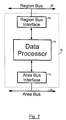
- segment controller 30 has a data processor 68 which interfaces with segment bus 15 (also seen in Fig. 1) via a segment bus interface 70, and further interfaces with area bus 32 (also seen in Fig. 1) via an area bus interface 72.
- area controller 26 (also seen in Fig. 1) has a construction analogous to that of segment controller 30. Accordingly, area controller 26 has a data processor 74 which interfaces with area bus 32 (also seen in Fig. 1) via an area bus interface 76, and further interfaces with region bus 28 (also seen in Fig. 1) via a region bus interface 78.
- system controller 18 shown in Fig. 8, is seen to be generally analogous to both that of segment controller 30 and area controller 26, having a data processor 80 which interfaces with system bus 22 (also seen in Fig. 1) via a system bus interface 82. It will be appreciated that system bus 22 may interface directly with region controller 20 (Fig. 1). However, depending on the requirements of an individual system, there may be one or more intervening levels of communications between system controller 18 and region controller 20.
- inter-system communications link 84 may be optionally provided, wherein a plurality of transport systems may be interconnected so as to exchange information between systems. This may be required over a very large area, such as a continental land mass, wherein effectively a single continuous network of roads may be governed by several systems constructed in accordance with the invention. While the communications between different hierarchical levels are typically by means of data buses, inter-system link 84 is preferably a telecommunications-type data exchange.
- the length of a segment can be several hundred meters and even a number of kilometers.
- the number of road units 10 in any given segment can thus be between several hundred and several thousand.
- a communications network between each segment controller 30 and its associated road units 10 characterized by the following:
- All the road units 10 and their associated segment controller 30 are connected via appropriate interfaces 64 (Fig. 5), in parallel, to a single pair of wires which constitutes segment bus 15.
- the segment controller 30 is the master of the segment bus 15, and all the road units 10 are slaves, such that most routine communications are governed by the segment controller 30. With the exception of certain predetermined situations, such as the emergency braking procedure, described hereinbelow in conjunction with Fig. 12, which is a quasi-reflexive procedure, the function of the road units 10 is to respond to vehicle on-board units 34 in accordance with instructions received from the controller 30.
- Communication between controller 30 and its associated road units 10 is of necessity asynchronic. This is due mainly to different propagation times between road units located at different distances from the controller, and due to the fact that in order to conduct a sensible dialog between them, a given road unit and the controller have to receive complete messages from each other prior to responding.
- a segment controller-road unit transmission includes the following parts:
- a road unit-segment controller transmission includes the following parts:
- the segment controller 30 When initiating a transmission to one or more road units 10, the segment controller 30 instructs a particular road unit or group of road units them what they are required to do. This may be routine reporting of vehicle travel, detailed reporting procedure, self-check procedure, change in function, and so on.
- Fig. 6B is divided into transmission plots A - E, wherein A is a plot of controller-road units transmissions, B, C and D are plots of road unit response transmissions, and E is a combined plot, showing all transmissions between the controller and the road units.
- An instruction transmission from the controller to the road units is indicated at 150 in plot A of the drawing.
- the segment controller 30 Immediately upon termination of its instruction transmission 150, the segment controller 30 begins to transmit clock pulses 152, preferably of polarity opposite to that of the instruction transmission.
- Each clock pulse advances the address counter in each road unit data processor 62.
- the road unit checks if the address currently indicated by counter corresponds to its own personal identification number.
- the road units in the segment are numbered sequentially.
- the road unit data processor 62 checks if it needs to pass on a message to the controller. If so, it will transmit its response, as seen at 154, 156 and 158 for respective road units "l", “m”, and "n".. If not, it will not respond as, in the presently described routine mode, if no vehicle has passed over the road unit since it previous report, it does not need to transmit.
- the controller waits for an answer, it being appreciated that the waiting time is predetermined in accordance with the longest propagation time in the segment.
- the controller ceases to transmit clock pulses 152 and receives the answer.
- the answer has a defined structure such that the controller 30 identifies its end.
- the controller resumes transmission of the clock pulses 152.
- the controller processes the information received from the road units and decides how to continue.
- the transport system of the present invention is based on communications (radio or otherwise) between vehicles 16 (Figs. 1, 4A and 4B) and a roadway-based communications network, substantially as described above in conjunction with Figs. 1-8.
- road units 10 (Figs. 1, 3, 4A and 4B) broadcast short transmissions only in response to a triggering or probing signal emitted by the transceiver 36 (Fig. 4A) of a vehicle on-board unit 34 passing above them.
- transmissions between on-board unit 34 road units 10 contain information, and signals enabling centering of the vehicle 16 over the line units 10.
- a human operator Prior to and during a journey by a vehicle 16 having installed therein an on-board system 34 (Fig. 4A), a human operator, referred to below as “driver”, can enter a desired destination into data processor 38 via a suitable manual data entry device 39.
- device 39 is a suitable keyboard, although other suitable types of device, such as joystick- or mouse-based devices or an oral instruction-responsive device may additionally, or alternatively, be employed for this purpose.
- the driver is provided with visual or audio-visual instructions which details a journey route recommended by the system, taking into account geographical knowledge of the road system, topographical, present traffic, roadwork, and weather considerations.
- the system can also be programmed to take account of many additional factors. Accordingly, since the system has extensive and up-to-date knowledge of road conditions and other variables affecting the journey, it is able to plan a route and optimum speeds for any vehicle, taking into account factors which include, inter alia, safety, time and cost.
- the driver may accept the suggestion of the system or enter another route as he wishes. If his choice is possible taking into account driving conditions, it will be confirmed by the system. From this moment the driver can enter an "automatic driving" instruction via data entry device 39, thereby to transfer the vehicle 16 to automatic driving and to allow the system to drive the vehicle to the destination.
- the driver can take control of the vehicle at any time by entering a predetermined "manual driving" instruction accordingly. This can be done, for example, by manual operation of any of the vehicle controls.
- a typical multi-lane highway referenced 90, is divided into three lanes, labeled "lane 1", “lane 2" and "lane 3".
- Each lane has installed along its longitudinal axis, preferably beneath the surface thereof, a communications cable 13 (also seen in Figs. 3, 4A and4B).
- a predetermined length of communications cable 13, together with the road units 10 connected thereto, constitute a segment, substantially as described above in conjunction with Figs. 1 and 2.
- branch communications cables In addition to the main, centrally-located communications cables 13, there are also provided, in predetermined locations, branch communications cables, referenced 13a, 13b, 13c and 13d. These branch cables connect longitudinal cables 13 of parallel segments so as to enable passage of automatically controlled vehicles 16 (Figs. 1, 4A and 4B) from lane to lane or, in terms of the system, from segment to segment.
- one or more communication cables 13e may also be provided along the ramp 92 in order to allow automated entry to/exit from the highway 90.
- inter-segment serial links via which instructions or data can be transmitted from one segment to an adjacent segment. This may be needed, for example, when a vehicle is being navigated from one lane to another, or when turning, or to warn road units 10 and vehicles in adjacent segments of an emergency situation.
- road units 10 While virtually all of road units 10 are connected in series to two adjacent (upstream and downstream) road units, a plurality of nodal road units, referenced 10', are connected additionally to road units in an adjacent branch communications cable, thereby enabling passage of vehicles 16 from lane to lane. It will be appreciated, however, that "end" road units, referenced 10" in Fig. 1, are connected to a single road unit only.
- the vehicles 16 travel along a certain route which the system has provided for them according to certain criteria, which include:
- “Turn” instructions are transferred as instructions for action to the road units 10 via the various system levels and, ultimately, via the segment controllers 30 (Figs. 1 and 6). Execution of turns in accordance with the turn instructions are managed "in the field" by the road units 10 and segment controllers 30. During execution of turns the road units 10 and segment controllers 30 take into account the operating conditions and spacing of vehicles in the vicinity of the turning vehicle, and how the turning of the turning vehicle will affect them.
- the junction 100 connects two pairs of intersecting lanes 102, and permits forward travel and right and left turns, by virtue of inner branch cables 104 and outer branch cables 106.
- Inner branch cables 104 enable a vehicle to turn while crossing a flow of opposing traffic
- outer branch cables 106 enable a vehicle to turn but wherein it is not required to cross a flow of opposing traffic.
- each road unit 10 is connected to a pair of upstream and downstream road units via communications cable 13, while nodal road units 10' (also seen in Fig. 9) connect between a communications cable 13 and an associated branch cable 113.
- Branch cable 113 has substantially the same construction has cable 13.
- Each road unit 10 is further connected via segment bus 15 to an associated segment controller 30, it being further seen that each branch cable is similarly connected to a segment branch bus, referenced 15', thereby to form an integral part of a predetermined segment.
- segment controllers 30 are connected to an area controller 26 via an area bus 32; area controllers 26 are connected (not shown) to region controller 20 via region bus 28; and a region controller is ultimately connected, via any intervening system levels, to system controller 18, which, in turn, may be connected to other system controllers via an inter-system link 84 (seen also in Fig. 8).
- link 84 is shown as a radio transmitter.
- a minimum transmission rate "Tr” from the vehicle on-board unit to a road unit and vice versa is represented by the expression Tr>2*(Ctr+Ltr)/Tc and is in the order of 24 Kb/s. In practice this may be several orders of magnitude greater.
- FIG. 9 is a series of graphs depicting communications timing between a vehicle traveling at a velocity of 200 kph and road units I, II and III. The graphs in Fig. 11 are as follows:
- the road units 10 transmit only in response to detection of a transmission from on-board unit 34.
- the on-board unit 34 broadcasts "probing" transmissions, typically of about 4 milliseconds in length, every 9 milliseconds. This is seen in graph (a) in Fig. 11, wherein a four millisecond transmission is seen to be transmitted at 0, 9 and 18 milliseconds.
- the road unit 10 When a transmitting vehicle is located within communication range of a road unit antenna 58 (Fig. 5) or thereover, as illustrated in Fig. 4B, the road unit 10 is operative to detect a probing transmission from the on-board unit 34 so as to be "triggered” thereby. In response to being triggered in this manner, the road unit 10 responds with a broadcast lasting approximately 4 milliseconds, 4 milliseconds after the broadcast of the on-board unit 34 has ended. This is seen in graphs (a) and (c) in which, at 26 milliseconds - 4 milliseconds after the end of the first full transmission detected by the road unit - the road unit I transmits a 4 millisecond transmission.
- the road unit 10 receives an unidentified transmission (which is not compatible with the structure of the vehicle transmission) it does not respond. This can occur, for instance, when only part of a message is received due to the on-board unit 34 being out of range of the road unit antenna at the start of transmission.
- This is exemplified in graphs (a) and (b) wherein it is seen that, at the beginning of the second probing transmission from on-board unit 34, at 9 milliseconds, the vehicle has not yet entered the communication range of road unit I. Accordingly, as not all of the 9-13 millisecond pulse is detected by road unit I, it ignores the part-transmission and responds only to the subsequent 18-22 millisecond and 34-38 millisecond transmissions.
- the on-board unit 34 resumes its probing transmissions. This resumption to a regular probing transmission pattern is seen in response to the road unit I transmission at 42-46 milliseconds - graph (c), the road unit II transmission at 83-87milliseconds - graph (e), and the road unit III transmission at 124-128 milliseconds - graph (g).
- each road unit converses with on-board unit 34 of a particular vehicle twice only. This is due to operational considerations, such as affected by vehicle speed and transmission rate. In certain predetermined cases, however, when the vehicle speeds are very low or when a large amount of information is to be transferred to the vehicle at an increased transmission rate, more than two exchanges between the on-board unit and each road unit may occur. The circumstances in which this happens are determined by controllers at various system levels in accordance with predetermined criteria.
- the on-board unit 34 Prior to entering a roadway forming part of the system of the invention (the "roadway"), the on-board unit 34 has no (radio) connection with the system. Driving is therefore manual and carried out according to regular driving principles.
- the driver activates the on-board unit 34 via switch 35 (Fig. 4A). After activation, unit 34 carries out a self-check procedure and notifies the driver of the results of the check.
- the messages to the driver are provided via visual display 52 and, optionally, via speaker 54. If the system self-check indicates no malfunction the driver is asked to enter a journey destination via data entry device 39.
- the driver keys in his destination (the names of all geographical locations covered by the system are in the memory of the on-board data processor 38).
- the name of the destination is checked by the data processor and appropriate confirmation is given to the driver via display 52 and/or speaker 54.
- the on-board unit 34 transmitter starts transmitting the transmission codeword or identification of the vehicle, via the main antenna 56 which is installed beneath the vehicle.
- the codeword which also functions as the above-described probing transmission, is 100 bits long and is of 4 milliseconds duration.
- the code is transmitted regularly every 9 milliseconds until 'contact' is made with the system, as described above in conjunction with Fig. 11.
- the driver drives the vehicle onto the road manually, with the center of the vehicle over the communications cable 13.
- a road unit 10 detects receives the probing transmission so as to be triggered thereby, it responds immediately with a confirmation broadcast. From this moment, until the vehicle either leaves a roadway encompassed by the system of the invention, or unless the driver deactivates on-board unit 34 via switch 35, the system takes over driving of the vehicle.
- the road unit 10 first encountered by the vehicle transfers the driver's destination request to the segment controller 30 (Fig. 1). If the destination is within the segment whereat the vehicle is located at the time of the request ("the vehicle segment"), the request is processed directly by the segment controller 30, which subsequently transmits an appropriate message via appropriate road units 10, back to the on-board unit 34.
- the segment controller 30 transmits the destination request, via an area bus 32, to an area controller 26. If the destination is within the vehicle area, the journey destination is processed by the area controller 26. If the journey destination is not within the vehicle area, the journey destination data is transmitted to controllers at successively higher levels in the system hierarchy, until the appropriate level of hierarchy is reached. Subsequently, output data corresponding to the journey destination is transmitted downward through the various system levels, until it is received by the on-board main antenna 56.
- the driver receives confirmation.
- the confirmation includes information regarding the selected route, the expected duration of the journey and other messages as necessary.
- the driver may either confirm, cancel or request changes in the route via data entry device 39.
- the controllers at the various levels transmit operational instructions to road units located along the route. These instructions may include the vehicle code, other vehicle particulars, estimated time of arrival at each road unit, navigational details, and speed of travel, as well as miscellaneous instructions to the on-board unit 34 and messages to the driver.
- the road unit 10 in the immediate vicinity of the vehicle then initiates transmittal of operational instructions to the on-board unit 34, and the vehicle which commences automatic travel.
- the driver Prior to reaching a predetermined exit location from the roadway, from where manual driving will be required, the driver receives a warning message via display 52 and/or speaker 54 of the impending exit.
- the on-board unit 34 subsequently reduces the driving speed of the vehicle to manual driving level.
- each road unit 10 stores in its memory (data processor 62) the data of each vehicle expected, in arrival order (FIFO).
- the size of the road unit memory determines the number of vehicles it is possible to store.
- Vehicle journey data may be updated via the segment controller 30 (Figs. 1 and 6) when necessary.
- the data may include, inter alia, the vehicle identification or codeword, estimated time of arrival, average expected journey speed, navigational instructions, as well as any further instructions to the on-board unit 34 and miscellaneous messages to be transmitted to the driver.
- the road units 10 are in a standby mode until a valid transmission (transmission structure, coding method, and so on) is received from a vehicle.
- a valid transmission transmission structure, coding method, and so on
- the receiving road unit checks data received from the on-board unit 34, including the vehicle codeword or identification number, vehicle data, and miscellaneous messages.
- the road unit waits for the second transmission from the on-board unit 34. If the identification number is incorrect in the second transmission as well, the road unit enters an emergency braking procedure. This is described below in conjunction with Fig. 12.
- the road unit data processor 62 processes the messages. These messages may include a request for change in route, a request for specific geographic, commercial or any other general type of information, transfer of messages to stationary stations such as a private or business address. The messages are transferred for action to the segment controller 30, which either processes them and responds directly, or transmits the messages to a higher system level.
- a further function of the road units is to check if the actual vehicle arrival time is as expected. If not, data processor 62 calculates a required change in speed, and instructs on-board data processor 38 (Fig. 4A) accordingly, which then acts to change the speed via control interface 40. If the difference between actual and required speed is greater than a value predetermined in accordance with criteria such as, the speed of travel in the segment, planned distances between vehicles, safety conditions in the segment, the emergency braking procedure may be initiated.
- the road unit transmits a response to the vehicle on-board unit 34.
- the response may include instructions generated by the road unit, such as, change of speed, emergency braking and the like, and instructions and messages from the segment controller, such as, average journey speed so far, navigational instructions, and miscellaneous messages.
- the road unit In addition to the transmissions from a given road unit to a given vehicle on-board unit, the road unit also transmits a message via serial link 14 to the next (downstream) road unit in the direction of travel.
- the message includes, inter alia, the identification number of the vehicle next scheduled to reach it and how long it will take to arrive or "instantaneous arrival time.”
- the instantaneous arrival time is based on the actual speed of the vehicle as it passes the transmitting road unit and any speed change or navigational instructions, and is thus different from the estimated time of arrival according to the travel plan, as transmitted to the receiving road unit by the segment controller.
- the downstream road unit constantly checks if the vehicle which has just left the upstream road unit, and which should reach the downstream road unit in a given time, has indeed arrived as expected. If the vehicle is found not to have arrived within the expected time period, the road unit enters the emergency braking procedure.
- the upstream road unit stores various predetermined types of data of the vehicle which has passed in its memory. For this purpose it can use the same place in its memory on which were written the data it transmitted to the on-board unit 34 and which it no longer needs.
- Each road unit transfers messages to its segment controller 30 via parallel communications bus 15 (Fig. 1) in accordance with a predetermined procedure.
- the messages include, inter alia, a report on the passage of vehicles and messages associated with each vehicle; information concerning special occurrences, such as, emergency braking; service requests of the road unit itself, for instance, a request for memory update; messages concerning faults in the line; and so on.
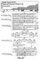
- Fig. 12 is a flow chart diagram of an emergency braking procedure, in accordance with an embodiment of the invention.
- Emergency braking of one or more vehicles may be initiated by the system, in response to a plurality of predetermined conditions listed below; by one or more road units 10 as a reflexive response to various predetermined situations, for example, if a vehicle does not reach a specific road unit within an expected time period, or if the vehicle is found to be malfunctioning; or by the driver.
- entry of an appropriate instruction to on-board unit 34 either via data entry device 39 or by depressing the vehicle brake pedal, for example, will cause the system to enter an emergency braking procedure.
- Conditions in response to which the system initiates emergency braking include the following:
- a typical emergency braking procedure is as follows:
Landscapes
- Engineering & Computer Science (AREA)
- Physics & Mathematics (AREA)
- General Physics & Mathematics (AREA)
- Aviation & Aerospace Engineering (AREA)
- Radar, Positioning & Navigation (AREA)
- Remote Sensing (AREA)
- Automation & Control Theory (AREA)
- Electromagnetism (AREA)
- Traffic Control Systems (AREA)
- Control Of Position, Course, Altitude, Or Attitude Of Moving Bodies (AREA)
- Threshing Machine Elements (AREA)
- Control Of Conveyors (AREA)
- Container, Conveyance, Adherence, Positioning, Of Wafer (AREA)
- Warehouses Or Storage Devices (AREA)
Claims (28)
- Système de transport comprenant:chacune desdites unités de commande de segments comporte:un réseau de routes de passage à intersections (12) auquel est associé un réseau correspondant d'unités de communication basé sur les routes (10), ainsi queplusieurs véhicules (16) pour circuler sur ledit réseau de routes à intersections, etun système de commande et de communication pour commander la circulation des véhicules sur ledit réseau,dans lequel le réseau est subdivisé en plusieurs segments continus, et caractérisé en ce que le système de commande et de communication est un système modulaire hiérarchique décentralisé, assurant une commande individualisée en temps réel de chacun desdits véhicules dans ledit réseau et le guidage de celui-ci jusqu'à une destination de trajet choisie, tout en tenant compte de l'état fonctionnel et du guidage des autres dits véhicules circulant dans ledit réseau, ledit système de commande et de communication comprenant:au moins des premier, deuxième et troisième niveaux hiérarchiques d'intercommunication pour le contrôle et la communication, dans lesquelsledit premier niveau comporte un moyen de commande et d'échange de données (34) monté à bord du véhicule;ledit deuxième niveau comporte plusieurs desdites unités basées sur la route et disposées en série le long de chaque segment de façon que chacune desdites unités basées sur la route localisée sur un trajet de circulation choisi fonctionne à son tour pour établir une communication bidirectionnelle avec ledit moyen de commande et d'échange de données (34) monté à bord de chaque véhicule circulant sur ledit segment,ledit moyen de commande et d'échange de données (34) monté à bord fonctionnant également pour utiliser lesdites communications bidirectionnelles pour fournir un positionnement latéral et longitudinal dudit véhicule par rapport à un trajet de déplacement; etledit troisième niveau comprenant plusieurs unités de commande de segments de réseaux d'intercommunication (30) pour le traitement des données et les communications directionnelles avec chacune desdites unités basées sur la route dans l'ensemble correspondant des segments de réseau prédéterminés,dans lequel chacun desdits moyens de commande et d'échange de données (34) monté à bord fonctionne pour détecter et commander de manière sélective les opérations fonctionnelles de chacun desdites véhicules de façon à permettre le guidage automatique de celui-ci vers une destination de déplacement choisie, lesdites communications bidirectionnelles entre chacun desdits moyens de commande et d'échange de donnée (34) montés à bord et lesdites unités basées sur la route à proximité de celle-ci comportant au moins la transmission entre elles de données d'identification mutuelle et la transmission de données fonctionnelles du véhicule provenant dudit moyen (34) monté à bord vers lesdites unités basées sur la route, etdans lequel ledit moyen de commande et d'échange de données (34) monté à bord de chacun desdits véhicules fonctionne pour maintenir des communications bidirectionnelles avec au moins l'une desdites unités (10) basées sur la route à tout moment pendant le fonctionnement du véhicule, etet dans lequel, en réponse à la réception de données de fonctionnement de véhicules, ledit moyen pour évaluer les paramètres de circulation optimaux fonctionne pour réévaluer lesdits paramètres de circulation et pour mettre à jour lesdits ordres de fonctionnement de véhicule conformément à ces paramètres.un moyen d'interface (70) pour échanger avec chacune desdites diverses unités basées sur la route située dans chacun desdits segments de réseau au moins des données d'identification et de fonctionnement de chacun desdits véhicules circulant dans un segment de réseau choisi à proximité desdites diverses unités basées sur la route dans celui-ci; etun moyen (68) pour évaluer les paramètres de circulation optimaux pour chacun desdits véhicules,dans lequel ledit moyen d'interface fonctionne pour transmettre auxdites unités basées sur la route des ordres de fonctionnement des véhicules pour chacun desdits véhicules à proximité de celui-ci, conformément auxdits paramètres de circulation optimaux,dans lequel lesdites unités basées sur la route fonctionnent pour transmettre lesdits ordres de fonctionnement de véhicule auxdits véhicules circulant à proximité de celles-ci,
- Système de transport selon la revendication 1, comprenant, en outre, au moins un quatrième niveau hiérarchique de commande et de communication qui comporte au moins une super-unité de commande (26) pour le traitement des données et les communications bidirectionnelles avec plusieurs unités de commande de segments qui commandent ensemble le fonctionnement des véhicules dans une zone contenant un certain nombre prédéterminé desdits segments de réseau contigus,
dans lequel chacun desdits moyens de commande de segments comporte, en outre, un moyen d'interface supplémentaire (72) pour échanger, par des moyens de bus parallèles (32), entre chacune desdites unités de commande de segments (30) et ladite super-unité de commande (26), des données supplémentaires relatives aux véhicules qui, conformément à des critères prédéterminés, peuvent influencer l'évaluation desdits paramètres de circulation d'autres véhicules circulant dans toute partie de la zone contenant ledit nombre prédéterminé de dits segments de réseau contigus,
et dans lequel chacune desdites super-unités de commande (26) comporte:un moyen d'interface (76) pour échanger avec lesdites unités de commande de segments, lesdites données supplémentaires relatives aux véhicules, etun moyen (74) pour traiter lesdites données supplémentaires relatives aux véhicules, de façon à fournir des données de circulation supplémentaires,dans lequel ledit moyen d'interface (76) de ladite super-unité de commande fonctionne pour transmettre audit moyen d'interface (72) de chacune desdites unités de commande de segments lesdites données de circulation supplémentaire utiles pour l'évaluation desdits paramètres de circulation optimaux des véhicules circulant dans ledit segment de réseau associé à celui-ci. - Système de transport selon la revendication 2, dans lequel ledit système comprend en outre d'autres niveaux hiérarchiques de commande ayant chacun plusieurs desdites super-unités de commande pour commander les véhicules dans une région prédéterminée contenant plusieurs zones contiguës, chacun desdits niveaux fonctionnant pour commander un niveau de commande immédiatement en dessous de lui dans la hiérarchie, chacun desdits niveaux de commande hiérarchique comprenant:
au moins un moyen de communication pour communiquer de manière sélective avec un niveau de commande immédiatement inférieur en réponse à la réception de signaux d'entrée provenant de celui-ci; et au moins un moyen de traitement de données connecté à chacun desdits moyens de communication dudit niveau hiérarchique de commande pour traiter les données d'entrée correspondant auxdits signaux d'entrée et pour fournir des données de sortie pour la transmission par ledit moyen de communication au niveau de commande immédiatement inférieur sous la forme de signaux de sortie. - Système de transport selon la revendication 1, dans lequel ledit moyen pour évaluer les paramètres de circulation optimaux (68) fonctionne pour fournir des données de fonctionnement de véhicule pour plusieurs véhicules à plusieurs desdites unités de route (10) situées sur les trajets de déplacement correspondants desdits divers véhicules et chacune desdites unités de route (10) fonctionnant pour mettre en mémoire lesdites données et fonctionnant en outre en réponse à la réception de l'identité de chacun desdits véhicules provenant desdits moyens (34) montés à bord de ceux-ci pour fournir les données fonctionnelles pour ledit véhicule associé à celles-ci.
- Système de transport selon la revendication 1, dans lequel chacune desdites unités basées sur la route est connectée, par un moyen de communication parallèle (64) et un moyen de bus parallèle (15), à une unité prédéterminée faisant partie desdites unités de commande de segments (30) et dans lequel chacune desdites unités basées sur la route comporte:un moyen de transmission et de réception (60);un moyen d'antenne (58) pour faciliter les communications entre ledit moyen monté à bord (34) et ledit moyen de transmission et de réception (60); etun moyen de traitement de données (62) associé audit moyen de transmission et de réception (60) pour recevoir des données provenant dudit moyen monté à bord (34) et pour transmettre des données à celui-ci afin d'échanger des données avec une unité de commande de segments associée (30) par ledit moyen de communication parallèle (64) et ledit moyen de bus parallèle (15) et pour traiter les données reçues dudit moyen monté à bord (34) et provenant de ladite unité de commande de segments associée (30).
- Système de transport selon la revendication 5, dans lequel chacune desdites unités basées sur la route est connectée en outre, par un bus sériel (14), à au moins une unité adjacente basée sur la route, dans lequel chacune desdites unités basée sur la route comporte également un moyen supplémentaire de transmission et de réception (66) pour échanger des données entre lesdites unités voisines basées sur la route.
- Système de transport selon la revendication 6 et comprenant un dispositif à câble (13) contenant au moins plusieurs desdites unités basées sur la route (10), lesdits bus sériels (14) entre celles-ci et lesdits moyens de bus parallèles (15, 32).
- Système de transport selon la revendication 6 et comprenant également un moyen de bus sériel (14') connectant entre elles des unités présélectionnées basées sur la route de segments voisins, dans lequel une première unité basée sur la route d'un premier segment fonctionne pour échanger avec une deuxième unité basée sur la route d'un deuxième segment, par ledit moyen de bus sériel (14'), des données relatives aux véhicules circulant depuis ledit premier segment vers ledit deuxième segment, de façon à faciliter ainsi la commande continue desdits véhicules par ledit système.
- Système de transport selon la revendication 1, dans lequel ledit moyen de commande et d'échange de données (34) monté à bord et chacune desdites unités basées sur la route peuvent fonctionner de manière sélective dans soit un premier mode complètement automatique, soit dans un deuxième mode non complètement automatique avec "homme dans la boucle".
- Système de transport selon la revendication 1, dans lequel chacun desdits moyens de commande et d'échange de données (34) montés à bord comporte:un moyen de transmission et de réception (36) pour communiquer avec chacune desdites diverses unités (10) basées sur la route en série tout en circulant devant celles-ci;un moyen de traitement de données (38) connecté audit moyen de réception et de transmission (36);un moyen de commande (40) connecté audit moyen de traitement de données pour commander de manière sélective et détecter l'une quelconque desdites diverses fonctions de marche prédéterminées des véhicules en réponse aux signaux reçus par ledit moyen de transmission et de réception (36) en provenance desdites unités basées sur la route, dans lequel lesdites unités basées sur la route sont disposées le long d'un trajet prédéterminé le long dudit trajet de circulation et fonctionnent en combinaison avec ledit moyen (34) monté à bord pour permettre un positionnement prédéterminé dudit véhicule par rapport audit trajet prédéterminé.
- Système de transport selon la revendication 9, dans lequel ledit moyen d'interface (70) de ladite unité de commande de segments (30) fonctionne pour transmettre audit moyen de traitement de données (62) de chacune desdites unités (10) basées sur la route située le long desdits trajets de déplacement de plusieurs véhicules des données de circulation relatives à chacun desdits véhicules de façon que chacune desdites unités basées sur la route fonctionne pour anticiper l'arrivée de véhicules aux identités connues.
- Système de transport selon la revendication 10, dans lequel ledit moyen de commande et d'échange de données (34) monté à bord comprend également un premier moyen d'antenne (44) monté dans une position prédéterminée sur ledit véhicule et associé audit moyen de traitement de données (38) et ledit moyen d'antenne (58) de chacune desdites unités basées sur la route est un deuxième moyen d'antenne,
dans lequel une antenne prédéterminée faisant partie du premier et du deuxième moyen d'antenne comporte une paire d'antennes disposées avec une orientation prédéterminée et ayant un moyen de réception (50) et un moyen de comparaison (48) associés à celle-ci pour fournir une indication de sortie de la position dudit véhicule relative audit trajet prédéterminé. - Système de transport selon la revendication 12, dans lequel ladite paire d'antennes (44), ledit moyen de réception (50) et ledit moyen de comparaison (48) font partie dudit moyen de commande et d'échange de données (34) monté à bord dudit véhicule et sont connectés audit moyen de traitement de données (38) de celui-ci.
- Système de transport selon la revendication 13, dans lequel l'espace longitudinal entre les unités voisines basées sur la route est égal ou inférieur à l'intervalle longitudinal de réception dudit moyen de commande et d'échange de données (34) monté à bord, de façon que ledit moyen (34) monté à bord soit toujours dans un intervalle de communication d'au moins une unité basée sur la route le long de son trajet de circulation.
- Système de transport selon la revendication 10, dans lequel ladite paire d'antennes et ledit moyen de comparaison fonctionnent pour fournir des signaux audit moyen de traitement de données afin d'indiquer le degré d'alignement dudit véhicule sur ledit trajet prédéterminé.
- Système de transport selon la revendication 15, dans lequel ledit moyen de commande et d'échange de données (34) monté à bord comprend également une antenne de communication principale (56) connectée audit moyen de transmission et de réception (36) pour recevoir et transmettre des messages de données entre ledit moyen de traitement de données (38) et lesdites unités basées sur la route.
- Système de transport selon la revendication 16, dans lequel lesdites unités basées sur la route (10) fonctionnent dans différents modes de fonctionnement et ledit moyen de traitement de données (68) de ladite unité de commande de segments (30) fonctionne également par l'intermédiaire dudit moyen d'interface (70) pour commander de manière sélective lesdites unités basées sur la route (10), de façon à commuter celles-ci entre un mode de fonctionnement et l'autre mode.
- Système de transport selon la revendication 10, dans lequel ledit moyen de traitement de données (38) fonctionne par l'intermédiaire dudit moyen de transmission et de réception (36) pour fournir des signaux de sortie auxdites unités basées sur la route, lesdits signaux de sortie comprenant des messages d'un type choisi dans le groupe constitué de:données d'identification du véhicule;messages indiquant les paramètres fonctionnels du véhicule;messages indiquant les caractéristiques du véhicule ou du conducteur; etdes messages de demande de données provenant du conducteur.
- Système de transport selon la revendication 18, dans lequel lesdites unités basées sur la route fonctionnent pour recevoir des signaux de sortie provenant dudit moyen de transmission et de réception (36) dudit moyen (34) monté à bord et fonctionnent en outre pour traiter les données contenues dans les signaux de sortie reçus et pour transmettre de manière sélective au moins une partie des données à une unité de commande de segments associée (30) et ledit moyen de traitement de données (68) de ladite unité de commande de segments fonctionne pour communiquer sélectivement avec chacune desdites diverses unités basées sur la route par l'intermédiaire dudit moyen d'interface (70) en réponse à la réception des signaux d'entrée provenant de celui-ci et ledit moyen (68) pour évaluer les paramètres de circulation fonctionne, en outre, pour fournir lesdits ordres de fonctionnement du véhicule auxdites unités basées sur la route sous la forme de signaux de sortie.
- Système de transport selon la revendication 19, dans lequel chacune desdites unités basées sur la route fonctionne en réponse à la détection du passage dudit véhicule pour transmettre un signal de sortie à au moins une unité basée sur la route située immédiatement en aval pour indiquer le passage dudit véhicule en direction de ladite unité située en aval.
- Système de transport selon la revendication 19, dans lequel ledit réseau de trajet de circulation comprend également des branchements qui divergent depuis des unités nodales basées sur la route (10'), chacune desdites unités nodales basées sur la route étant disposée en relation générale d'équidistance par rapport à une paire d'unités basées sur la route (10) immédiatement voisines situées en aval sur des trajets divergents et dans lequel chacune desdites unités nodales basées sur la route (10') fonctionne en réponse à la détection du passage dudit véhicule pour transmettre un signal de sortie à au moins ladite paire d'unités basées sur la route situées immédiatement en aval pour indiquer le passage dudit véhicule en direction d'une unité de ladite paire.
- Système de transport selon la revendication 19, dans lequel ledit réseau de trajet de circulation comprend également des jonctions et dans lequel chacun desdits véhicules est guidé dans la jonction par ledit système de commande et de communication.
- Système de transport selon la revendication 22, dans lequel lesdites jonctions comprennent des jonctions multidirectionnelles ayant au moins trois bandes de circulation d'entrée et trois bandes de circulation de sortie.
- Système de transport selon la revendication 19, dans lequel chacune desdites unités basées sur la route fonctionne en réponse à au moins l'une des valeurs des paramètres fonctionnels de véhicule et des valeurs d'entrée provenant du véhicule ou du conducteur, en dehors d'un intervalle prédéterminé pour transmettre automatiquement une indication d'état d'urgence directement à au moins l'une des unités voisines basées sur la route et dans laquelle chacune au moins desdites unités basées sur la route voisine fonctionne en réponse à la réception de ladite indication d'état d'urgence pour fournir un signal de commande audit moyen de transmission et de réception (36) dudit moyen de commande et d'échange de données (34) monté à bord, conformément à ladite indication de l'état d'urgence.
- Système de transport selon la revendication 24, dans lequel lesdites unités basées sur la route auxquelles l'indication de l'état d'urgence est transmise fonctionnent également pour fournir des signaux de commande audit moyen de transmission et de réception (36) dudit moyen de commande et d'échange de données (34) monté à bord de plusieurs desdits véhicules dont les données de circulation sont affectées par le véhicule dont les valeurs de paramètres ou les valeurs d'entrée sont déterminées comme étant en dehors de l'intervalle prédéterminé.
- Système de transport selon la revendication 24, dans lequel au moins ladite unité voisine basée su la route fonctionne en réponse à la réception de l'indication d'état d'urgence pour transmettre un signal de commande de vitesse audit moyen (34) monté à bord du véhicule.
- Système de transport selon la revendication 25, dans lequel plusieurs des unités basées sur la route et situées en amont et plusieurs unités basées sur la route et situées en aval par rapport à ladite unité basée sur la route transmettant automatiquement, fonctionnent pour activer les unités basées sur la route immédiatement voisines de celle-ci, de façon à transmettre les signaux de commande de vitesse à plusieurs moyens (34) montés à bord situés sur lesdits plusieurs véhicules dont les données de circulation sont affectés par le véhicule dont les valeurs de paramètres ou les valeurs d'entrée sont déterminées comme étant en dehors de l'intervalle prédéterminé.
- Système de transport selon la revendication 10, dans lequel ledit moyen de transmission et de réception (36) dudit moyen de commande et d'échange de données (34) monté à bord fonctionne pour fournir des signaux intermittents de vérification quand ledit véhicule circule sur un trajet de circulation et dans lequel lesdites unités basées sur la route comprennent un moyen pour détecter lesdits signaux de vérification et pour actionner lesdites unités basées sur la route en réponse à ceux-ci.
Applications Claiming Priority (3)
| Application Number | Priority Date | Filing Date | Title |
|---|---|---|---|
| IL10854994A IL108549A (en) | 1994-02-03 | 1994-02-03 | Transport system |
| IL10854994 | 1994-02-03 | ||
| PCT/GB1995/000204 WO1995021405A2 (fr) | 1994-02-03 | 1995-02-01 | Systeme de transport |
Publications (2)
| Publication Number | Publication Date |
|---|---|
| EP0772806A2 EP0772806A2 (fr) | 1997-05-14 |
| EP0772806B1 true EP0772806B1 (fr) | 1998-09-30 |
Family
ID=11065779
Family Applications (1)
| Application Number | Title | Priority Date | Filing Date |
|---|---|---|---|
| EP95907088A Expired - Lifetime EP0772806B1 (fr) | 1994-02-03 | 1995-02-01 | Systeme de transport |
Country Status (9)
| Country | Link |
|---|---|
| US (1) | US5928294A (fr) |
| EP (1) | EP0772806B1 (fr) |
| JP (1) | JP3365415B2 (fr) |
| AT (1) | ATE171793T1 (fr) |
| AU (1) | AU681491B2 (fr) |
| CA (1) | CA2180933C (fr) |
| DE (1) | DE69505136T2 (fr) |
| IL (1) | IL108549A (fr) |
| WO (1) | WO1995021405A2 (fr) |
Families Citing this family (131)
| Publication number | Priority date | Publication date | Assignee | Title |
|---|---|---|---|---|
| US5835376A (en) * | 1995-10-27 | 1998-11-10 | Total Technology, Inc. | Fully automated vehicle dispatching, monitoring and billing |
| US7113864B2 (en) * | 1995-10-27 | 2006-09-26 | Total Technology, Inc. | Fully automated vehicle dispatching, monitoring and billing |
| JP3268213B2 (ja) * | 1996-10-02 | 2002-03-25 | 三菱重工業株式会社 | 走行車両制御方法 |
| US6133853A (en) * | 1998-07-30 | 2000-10-17 | American Calcar, Inc. | Personal communication and positioning system |
| NL1006710C2 (nl) * | 1997-08-04 | 1999-02-25 | Frog Navigation Systems B V | Systeem en werkwijze voor het besturen van voertuigen. |
| JP3268239B2 (ja) * | 1997-08-21 | 2002-03-25 | 三菱重工業株式会社 | 走行車両群制御方法 |
| US6011508A (en) * | 1997-10-31 | 2000-01-04 | Magnemotion, Inc. | Accurate position-sensing and communications for guideway operated vehicles |
| US6101952A (en) * | 1997-12-24 | 2000-08-15 | Magnemotion, Inc. | Vehicle guidance and switching via magnetic forces |
| DE19816762A1 (de) * | 1998-04-16 | 1999-10-28 | Goetting Jun | Verfahren zur Energieversorgung sowie Positionierung und/oder Führung eines Objektes |
| JP3227489B2 (ja) | 1998-04-23 | 2001-11-12 | 国土交通省土木研究所長 | ダイナミックにチャネルを配分する車両通信システムおよび方法 |
| JP3495258B2 (ja) * | 1998-07-09 | 2004-02-09 | 三菱電機株式会社 | 交通情報提供装置 |
| CA2651874A1 (fr) * | 1998-11-05 | 2000-05-11 | International Truck And Engine Corporation | Systeme de communication pour vehicule terrestre et procede pour fournir des informations et coordonner les activites de plusieurs vehicules |
| US6577246B1 (en) * | 1999-05-25 | 2003-06-10 | Matsushita Electric Industrial Co., Ltd. | Electromagnetic wave lane marker, device for detecting electromagnetic wave lane marker, and traffic system |
| US6370452B1 (en) * | 1999-12-08 | 2002-04-09 | Samuel T. Pfister | Autonomous vehicle transit system |
| US6480783B1 (en) * | 2000-03-17 | 2002-11-12 | Makor Issues And Rights Ltd. | Real time vehicle guidance and forecasting system under traffic jam conditions |
| US6781524B1 (en) | 2000-03-17 | 2004-08-24 | Magnemotion, Inc. | Passive position-sensing and communications for vehicles on a pathway |
| GB0011797D0 (en) * | 2000-05-16 | 2000-07-05 | Yeoman Group Plc | Improved vehicle routeing |
| US6459965B1 (en) * | 2000-11-22 | 2002-10-01 | Ge-Harris Railway Electronics, Llc | Method for advanced communication-based vehicle control |
| US6772062B2 (en) | 2001-05-31 | 2004-08-03 | The Regents Of The University Of California | Intelligent ultra high speed distributed sensing system and method for sensing roadway markers for intelligent vehicle guidance and control |
| US20030231755A1 (en) * | 2002-06-18 | 2003-12-18 | Akhteruzzaman | Directory assistance |
| EP1451467B1 (fr) | 2001-10-01 | 2018-02-21 | Magnemotion, Inc. | Conception et fabrication de machines synchrones |
| US6983701B2 (en) | 2001-10-01 | 2006-01-10 | Magnemotion, Inc. | Suspending, guiding and propelling vehicles using magnetic forces |
| GB2384354A (en) * | 2002-01-18 | 2003-07-23 | Yeoman Group Plc | Navigation System |
| US7647232B2 (en) | 2002-02-21 | 2010-01-12 | Lockheed Martin Corporation | Real-time team coordination system for reconnaissance and surveillance missions |
| US6725152B2 (en) * | 2002-02-21 | 2004-04-20 | Lockheed Martin Corporation | Real-time route and sensor planning system with variable mission objectives |
| US6718261B2 (en) | 2002-02-21 | 2004-04-06 | Lockheed Martin Corporation | Architecture for real-time maintenance of distributed mission plans |
| US6687606B1 (en) | 2002-02-21 | 2004-02-03 | Lockheed Martin Corporation | Architecture for automatic evaluation of team reconnaissance and surveillance plans |
| US7174836B2 (en) * | 2002-04-05 | 2007-02-13 | Jervis B. Webb Company | Station control system for a driverless vehicle |
| US10308265B2 (en) | 2006-03-20 | 2019-06-04 | Ge Global Sourcing Llc | Vehicle control system and method |
| US10569792B2 (en) | 2006-03-20 | 2020-02-25 | General Electric Company | Vehicle control system and method |
| US9733625B2 (en) | 2006-03-20 | 2017-08-15 | General Electric Company | Trip optimization system and method for a train |
| KR100440588B1 (ko) * | 2002-06-10 | 2004-07-19 | 한국전자통신연구원 | 계층적 구조를 지원하는 직렬 버스형 형상 인식 및 경보장치 |
| US9950722B2 (en) | 2003-01-06 | 2018-04-24 | General Electric Company | System and method for vehicle control |
| US7725249B2 (en) * | 2003-02-27 | 2010-05-25 | General Electric Company | Method and apparatus for congestion management |
| US7860639B2 (en) * | 2003-02-27 | 2010-12-28 | Shaoping Yang | Road traffic control method and traffic facilities |
| JP2005043120A (ja) * | 2003-07-24 | 2005-02-17 | Honda Motor Co Ltd | 車両用ナビゲーションシステム |
| US7050903B1 (en) * | 2003-09-23 | 2006-05-23 | Navteq North America, Llc | Method and system for developing traffic messages |
| KR20070011577A (ko) | 2004-05-07 | 2007-01-24 | 마그네모션, 인코포레이티드 | 단일 경로를 기반으로 하는 작용기들을 이용한 3차원 동작 |
| US9376971B2 (en) * | 2006-03-20 | 2016-06-28 | General Electric Company | Energy management system and method for vehicle systems |
| US9828010B2 (en) | 2006-03-20 | 2017-11-28 | General Electric Company | System, method and computer software code for determining a mission plan for a powered system using signal aspect information |
| US8825239B2 (en) | 2010-05-19 | 2014-09-02 | General Electric Company | Communication system and method for a rail vehicle consist |
| US8935022B2 (en) | 2009-03-17 | 2015-01-13 | General Electric Company | Data communication system and method |
| US8798821B2 (en) | 2009-03-17 | 2014-08-05 | General Electric Company | System and method for communicating data in a locomotive consist or other vehicle consist |
| US8655517B2 (en) | 2010-05-19 | 2014-02-18 | General Electric Company | Communication system and method for a rail vehicle consist |
| US8702043B2 (en) | 2010-09-28 | 2014-04-22 | General Electric Company | Rail vehicle control communication system and method for communicating with a rail vehicle |
| US8532850B2 (en) | 2009-03-17 | 2013-09-10 | General Electric Company | System and method for communicating data in locomotive consist or other vehicle consist |
| US9637147B2 (en) | 2009-03-17 | 2017-05-02 | General Electronic Company | Data communication system and method |
| US9379775B2 (en) | 2009-03-17 | 2016-06-28 | General Electric Company | Data communication system and method |
| US8649899B2 (en) | 2006-06-19 | 2014-02-11 | Amazon Technologies, Inc. | System and method for maneuvering a mobile drive unit |
| US8220710B2 (en) * | 2006-06-19 | 2012-07-17 | Kiva Systems, Inc. | System and method for positioning a mobile drive unit |
| US7912574B2 (en) | 2006-06-19 | 2011-03-22 | Kiva Systems, Inc. | System and method for transporting inventory items |
| US20130302132A1 (en) | 2012-05-14 | 2013-11-14 | Kiva Systems, Inc. | System and Method for Maneuvering a Mobile Drive Unit |
| US7920962B2 (en) * | 2006-06-19 | 2011-04-05 | Kiva Systems, Inc. | System and method for coordinating movement of mobile drive units |
| US8538692B2 (en) * | 2006-06-19 | 2013-09-17 | Amazon Technologies, Inc. | System and method for generating a path for a mobile drive unit |
| US7873469B2 (en) | 2006-06-19 | 2011-01-18 | Kiva Systems, Inc. | System and method for managing mobile drive units |
| US8483903B2 (en) * | 2006-09-07 | 2013-07-09 | Nissan North America, Inc. | Vehicle on-board unit |
| US9037388B2 (en) * | 2006-11-17 | 2015-05-19 | Mccrary Personal Transport System, Llc | Intelligent public transit system using dual-mode vehicles |
| US8311730B2 (en) * | 2006-11-29 | 2012-11-13 | Neff Ryan A | Vehicle position determination system |
| US8532862B2 (en) * | 2006-11-29 | 2013-09-10 | Ryan A. Neff | Driverless vehicle |
| CA2685269C (fr) * | 2007-04-27 | 2014-07-08 | Kode Biotech Limited | Produits de synthese d'hydrates de carbone et de lipides et utilisation de ces derniers dans la prevention ou le traitement d'une infection virale |
| JP5057304B2 (ja) | 2007-06-08 | 2012-10-24 | 国立大学法人名古屋大学 | 車載通信システム及び車載通信方法 |
| SK50212008A3 (sk) * | 2008-02-26 | 2010-03-08 | Branislav Sit�R | Spôsob automatizovaného vedenia motorových vozidiel po cestných komunikáciach a systémové dopravné zariadenie |
| US9032880B2 (en) | 2009-01-23 | 2015-05-19 | Magnemotion, Inc. | Transport system powered by short block linear synchronous motors and switching mechanism |
| US8616134B2 (en) | 2009-01-23 | 2013-12-31 | Magnemotion, Inc. | Transport system powered by short block linear synchronous motors |
| US8483895B1 (en) | 2009-02-25 | 2013-07-09 | James J. Beregi | Transportation system, system components and process |
| US8583299B2 (en) | 2009-03-17 | 2013-11-12 | General Electric Company | System and method for communicating data in a train having one or more locomotive consists |
| US9834237B2 (en) | 2012-11-21 | 2017-12-05 | General Electric Company | Route examining system and method |
| GB2482119B (en) | 2010-07-19 | 2013-01-23 | China Ind Ltd | Racing vehicle game |
| US9513630B2 (en) | 2010-11-17 | 2016-12-06 | General Electric Company | Methods and systems for data communications |
| US10144440B2 (en) | 2010-11-17 | 2018-12-04 | General Electric Company | Methods and systems for data communications |
| KR102035771B1 (ko) * | 2011-05-20 | 2019-10-24 | 삼성전자주식회사 | 휴대용 단말기에서 위치 정보를 보상하기 위한 장치 및 방법 |
| US8892240B1 (en) | 2011-06-29 | 2014-11-18 | Amazon Technologies, Inc. | Modular material handling system for order fulfillment |
| AU2012283800B2 (en) * | 2011-07-14 | 2017-07-13 | Ge Global Sourcing Llc | Method and system for rail vehicle control |
| US8831984B2 (en) * | 2011-10-19 | 2014-09-09 | Amazon Technologies, Inc. | System and method for inventory management using mobile drive units |
| US8914170B2 (en) | 2011-12-07 | 2014-12-16 | General Electric Company | System and method for communicating data in a vehicle system |
| US20140310594A1 (en) * | 2013-04-15 | 2014-10-16 | Flextronics Ap, Llc | Configuration of haptic feedback and visual preferences in vehicle user interfaces |
| AU2013256565B2 (en) | 2012-04-30 | 2015-12-03 | Ossur Hf | Prosthetic device, system and method for increasing vacuum attachment |
| US9669851B2 (en) | 2012-11-21 | 2017-06-06 | General Electric Company | Route examination system and method |
| US9682716B2 (en) | 2012-11-21 | 2017-06-20 | General Electric Company | Route examining system and method |
| JP6351142B2 (ja) * | 2013-08-30 | 2018-07-04 | 三菱重工機械システム株式会社 | 運行管理システム、運行管理方法およびプログラム |
| US9802507B2 (en) | 2013-09-21 | 2017-10-31 | Magnemotion, Inc. | Linear motor transport for packaging and other uses |
| US10057719B2 (en) | 2013-11-27 | 2018-08-21 | Alan Snyder | Methods and systems for locating persons and places with mobile devices |
| US9251629B2 (en) * | 2013-12-03 | 2016-02-02 | Hti Ip, Llc | Determining a time gap variance for use in monitoring for disconnect of a telematics device |
| US10467896B2 (en) * | 2014-05-29 | 2019-11-05 | Rideshare Displays, Inc. | Vehicle identification system and method |
| US9892637B2 (en) | 2014-05-29 | 2018-02-13 | Rideshare Displays, Inc. | Vehicle identification system |
| US9405293B2 (en) * | 2014-05-30 | 2016-08-02 | Nissan North America, Inc | Vehicle trajectory optimization for autonomous vehicles |
| US9482544B1 (en) * | 2015-06-17 | 2016-11-01 | Nissan North America, Inc. | Electric vehicle efficiency profile management |
| US9776528B2 (en) | 2015-06-17 | 2017-10-03 | Nissan North America, Inc. | Electric vehicle range prediction |
| US9951704B2 (en) * | 2015-09-08 | 2018-04-24 | GM Global Technology Operations LLC | No start event monitoring |
| US10692126B2 (en) | 2015-11-17 | 2020-06-23 | Nio Usa, Inc. | Network-based system for selling and servicing cars |
| US10737667B2 (en) | 2016-06-23 | 2020-08-11 | Honda Motor Co., Ltd. | System and method for vehicle control in tailgating situations |
| US10449962B2 (en) | 2016-06-23 | 2019-10-22 | Honda Motor Co., Ltd. | System and method for vehicle control using vehicular communication |
| US10286913B2 (en) * | 2016-06-23 | 2019-05-14 | Honda Motor Co., Ltd. | System and method for merge assist using vehicular communication |
| US10332403B2 (en) | 2017-01-04 | 2019-06-25 | Honda Motor Co., Ltd. | System and method for vehicle congestion estimation |
| US10081357B2 (en) * | 2016-06-23 | 2018-09-25 | Honda Motor Co., Ltd. | Vehicular communications network and methods of use and manufacture thereof |
| US10625742B2 (en) | 2016-06-23 | 2020-04-21 | Honda Motor Co., Ltd. | System and method for vehicle control in tailgating situations |
| US20180012196A1 (en) | 2016-07-07 | 2018-01-11 | NextEv USA, Inc. | Vehicle maintenance manager |
| US9928734B2 (en) | 2016-08-02 | 2018-03-27 | Nio Usa, Inc. | Vehicle-to-pedestrian communication systems |
| US10031523B2 (en) | 2016-11-07 | 2018-07-24 | Nio Usa, Inc. | Method and system for behavioral sharing in autonomous vehicles |
| US10694357B2 (en) | 2016-11-11 | 2020-06-23 | Nio Usa, Inc. | Using vehicle sensor data to monitor pedestrian health |
| US10410064B2 (en) | 2016-11-11 | 2019-09-10 | Nio Usa, Inc. | System for tracking and identifying vehicles and pedestrians |
| US10708547B2 (en) | 2016-11-11 | 2020-07-07 | Nio Usa, Inc. | Using vehicle sensor data to monitor environmental and geologic conditions |
| US10699305B2 (en) | 2016-11-21 | 2020-06-30 | Nio Usa, Inc. | Smart refill assistant for electric vehicles |
| US10249104B2 (en) | 2016-12-06 | 2019-04-02 | Nio Usa, Inc. | Lease observation and event recording |
| US10074223B2 (en) | 2017-01-13 | 2018-09-11 | Nio Usa, Inc. | Secured vehicle for user use only |
| US10471829B2 (en) | 2017-01-16 | 2019-11-12 | Nio Usa, Inc. | Self-destruct zone and autonomous vehicle navigation |
| US9984572B1 (en) | 2017-01-16 | 2018-05-29 | Nio Usa, Inc. | Method and system for sharing parking space availability among autonomous vehicles |
| US10031521B1 (en) | 2017-01-16 | 2018-07-24 | Nio Usa, Inc. | Method and system for using weather information in operation of autonomous vehicles |
| US10464530B2 (en) | 2017-01-17 | 2019-11-05 | Nio Usa, Inc. | Voice biometric pre-purchase enrollment for autonomous vehicles |
| US10286915B2 (en) | 2017-01-17 | 2019-05-14 | Nio Usa, Inc. | Machine learning for personalized driving |
| US10897469B2 (en) | 2017-02-02 | 2021-01-19 | Nio Usa, Inc. | System and method for firewalls between vehicle networks |
| JP2018180962A (ja) * | 2017-04-13 | 2018-11-15 | ルネサスエレクトロニクス株式会社 | 安全運転支援システムおよび車載機 |
| US11397441B2 (en) | 2017-05-22 | 2022-07-26 | Arnold Chase | Bi-directional beacon information system |
| US10234302B2 (en) | 2017-06-27 | 2019-03-19 | Nio Usa, Inc. | Adaptive route and motion planning based on learned external and internal vehicle environment |
| CN109229102A (zh) * | 2017-07-04 | 2019-01-18 | 百度在线网络技术(北京)有限公司 | 无人驾驶车辆控制系统、方法和装置 |
| US10710633B2 (en) | 2017-07-14 | 2020-07-14 | Nio Usa, Inc. | Control of complex parking maneuvers and autonomous fuel replenishment of driverless vehicles |
| US10369974B2 (en) | 2017-07-14 | 2019-08-06 | Nio Usa, Inc. | Control and coordination of driverless fuel replenishment for autonomous vehicles |
| US10837790B2 (en) | 2017-08-01 | 2020-11-17 | Nio Usa, Inc. | Productive and accident-free driving modes for a vehicle |
| DE102017216507A1 (de) * | 2017-09-18 | 2019-03-21 | Osram Gmbh | Verkehrsteilnehmer, Verkehrssystem und Verfahren |
| US10635109B2 (en) | 2017-10-17 | 2020-04-28 | Nio Usa, Inc. | Vehicle path-planner monitor and controller |
| US10606274B2 (en) | 2017-10-30 | 2020-03-31 | Nio Usa, Inc. | Visual place recognition based self-localization for autonomous vehicles |
| US10935978B2 (en) | 2017-10-30 | 2021-03-02 | Nio Usa, Inc. | Vehicle self-localization using particle filters and visual odometry |
| US10717412B2 (en) | 2017-11-13 | 2020-07-21 | Nio Usa, Inc. | System and method for controlling a vehicle using secondary access methods |
| US10369966B1 (en) | 2018-05-23 | 2019-08-06 | Nio Usa, Inc. | Controlling access to a vehicle using wireless access devices |
| US11275370B2 (en) * | 2019-06-28 | 2022-03-15 | Zoox, Inc. | Techniques for navigating vehicles using teleoperator instructions |
| JP7201555B2 (ja) * | 2019-08-30 | 2023-01-10 | トヨタ自動車株式会社 | 車載ネットワークシステム |
| WO2021093967A1 (fr) | 2019-11-15 | 2021-05-20 | Volvo Truck Corporation | Système de commande sans fil pour véhicules autonomes fonctionnant dans une zone étendue |
| CN111199640B (zh) * | 2019-12-31 | 2022-02-01 | 新石器慧通(北京)科技有限公司 | 车辆编队的协同控制方法和装置 |
| JP7343437B2 (ja) * | 2020-04-02 | 2023-09-12 | トヨタ自動車株式会社 | 車両の運行管理装置、運行管理方法、および、交通システム |
| CN115705779B (zh) * | 2021-08-12 | 2025-09-12 | 深圳引望智能技术有限公司 | 轨迹信息的交互方法和装置 |
| DE102023100745A1 (de) * | 2023-01-13 | 2024-07-18 | Bayerische Motoren Werke Aktiengesellschaft | Verfahren und Vorrichtung zur automatischen Aufzeichnung einer Fahrtrajektorie |
Family Cites Families (16)
| Publication number | Priority date | Publication date | Assignee | Title |
|---|---|---|---|---|
| DE2631543A1 (de) * | 1976-07-14 | 1978-01-19 | Blaupunkt Werke Gmbh | Zielfuehrungssystem fuer kraftfahrzeuge |
| US4361202A (en) * | 1979-06-15 | 1982-11-30 | Michael Minovitch | Automated road transportation system |
| SE421731B (sv) * | 1980-07-01 | 1982-01-25 | Saab Scania Ab | Sett och anordning for fjerrstyrning av ett fordon eller en mobil maskin |
| JPS5759208A (en) * | 1980-09-26 | 1982-04-09 | Shinko Electric Co Ltd | Calling system for unmanned and guided vehicle |
| US5126941A (en) * | 1982-11-08 | 1992-06-30 | Hailemichael Gurmu | Vehicle guidance system |
| US5504683A (en) * | 1989-11-21 | 1996-04-02 | Gurmu; Hailemichael | Traffic management system |
| US5297049A (en) * | 1982-11-08 | 1994-03-22 | Hailemichael Gurmu | Vehicle guidance system |
| US5280431A (en) * | 1985-08-30 | 1994-01-18 | Texas Instruments Incorporated | Method for controlling the movements of a mobile robot in a multiple node factory |
| EP0229669A3 (fr) * | 1986-01-17 | 1988-06-29 | Litton Industrial Automation Systems, Inc. | Système de guidage par fil ou surface intégrés |
| EP0330639A3 (fr) * | 1988-02-25 | 1990-09-26 | Ndc Automation, Inc. | Système et méthode de commande de trafic de véhicule guidé automatiquement |
| FR2636750B1 (fr) * | 1988-08-26 | 1995-07-21 | Sgn Soc Gen Tech Nouvelle | Systeme de signalisation et de communication pour la gestion de la circulation d'objets mobiles autonomes |
| US4987540A (en) * | 1989-05-30 | 1991-01-22 | Whs Robotics, Inc. | Automatic guided vehicle system having communication and traffic controller with unguided paths |
| US5111401A (en) * | 1990-05-19 | 1992-05-05 | The United States Of America As Represented By The Secretary Of The Navy | Navigational control system for an autonomous vehicle |
| US5281901A (en) * | 1990-12-03 | 1994-01-25 | Eaton-Kenway, Inc. | Downward compatible AGV system and methods |
| CA2053028C (fr) * | 1990-10-23 | 1996-04-09 | Hideichi Tanizawa | Systeme de controle de la circulation de chariots |
| EP0618523B1 (fr) * | 1993-04-02 | 1998-12-09 | Shinko Electric Co. Ltd. | Méthode et dispositif de contrÔle pour la gestion d'un système de transport avec véhicules sans conducteur |
-
1994
- 1994-02-03 IL IL10854994A patent/IL108549A/en not_active IP Right Cessation
-
1995
- 1995-02-01 AU AU15423/95A patent/AU681491B2/en not_active Ceased
- 1995-02-01 WO PCT/GB1995/000204 patent/WO1995021405A2/fr not_active Ceased
- 1995-02-01 US US08/682,720 patent/US5928294A/en not_active Expired - Fee Related
- 1995-02-01 EP EP95907088A patent/EP0772806B1/fr not_active Expired - Lifetime
- 1995-02-01 AT AT95907088T patent/ATE171793T1/de active
- 1995-02-01 CA CA002180933A patent/CA2180933C/fr not_active Expired - Fee Related
- 1995-02-01 DE DE69505136T patent/DE69505136T2/de not_active Expired - Lifetime
- 1995-02-01 JP JP52045195A patent/JP3365415B2/ja not_active Expired - Fee Related
Also Published As
| Publication number | Publication date |
|---|---|
| JP3365415B2 (ja) | 2003-01-14 |
| DE69505136D1 (de) | 1998-11-05 |
| US5928294A (en) | 1999-07-27 |
| AU681491B2 (en) | 1997-08-28 |
| EP0772806A2 (fr) | 1997-05-14 |
| DE69505136T2 (de) | 1999-06-17 |
| JPH09508728A (ja) | 1997-09-02 |
| AU1542395A (en) | 1995-08-21 |
| ATE171793T1 (de) | 1998-10-15 |
| IL108549A0 (en) | 1994-05-30 |
| IL108549A (en) | 1998-08-16 |
| WO1995021405A3 (fr) | 1995-08-24 |
| CA2180933C (fr) | 1999-07-06 |
| WO1995021405A2 (fr) | 1995-08-10 |
| CA2180933A1 (fr) | 1995-08-10 |
Similar Documents
| Publication | Publication Date | Title |
|---|---|---|
| EP0772806B1 (fr) | Systeme de transport | |
| US5420794A (en) | Automated highway system for controlling the operating parameters of a vehicle | |
| CN109285373B (zh) | 一种面向整体道路网的智能网联交通系统 | |
| US10460601B2 (en) | Traffic management device and system | |
| US8676466B2 (en) | Fail-safe speed profiles for cooperative autonomous vehicles | |
| US20240249621A1 (en) | Roadway guidance system | |
| US6625540B2 (en) | Vehicle interference prevention device | |
| JP3520691B2 (ja) | 移動体制御システム | |
| US20130018572A1 (en) | Apparatus and method for controlling vehicle at autonomous intersection | |
| EP2280386B1 (fr) | Procédé et dispositif de programmation de véhicules à des intersections | |
| WO2019246246A1 (fr) | Systèmes d'autoroute de véhicules automatisés connectés et procédés relatifs à des véhicules lourds | |
| US20160176422A1 (en) | Light rail vehicle monitoring and stop bar overrun system | |
| CN111260946A (zh) | 一种基于智能网联系统的自动驾驶货车运营控制系统 | |
| US20030060968A1 (en) | Method and system for allowing vehicles to negotiate roles and permission sets in a hierarchical traffic control system | |
| JP2000516366A (ja) | 高速道路を制御する方法と装置 | |
| JP6867483B2 (ja) | 車両制御装置 | |
| US20210188273A1 (en) | Enhanced vehicle operation | |
| SK38297A3 (en) | A traffic control system, use of it, and a method of controlling the movement of a mobile unit | |
| CN114475662A (zh) | 一种基于环境感知和多车协同的车载智能控制系统 | |
| US20190086918A1 (en) | Road user, traffic system and method | |
| CN121158426A (zh) | 一种隧道智能无轨运输系统 | |
| CZ109093A3 (cs) | Zařízení pro zjištění projezdu oprávněných vozidel světelnými křižovatkami | |
| CN115691192A (zh) | 一种智能交通系统和方法 | |
| CN1161670A (zh) | 一种交通管制系统、它的应用和控制移动单元移动的方法 | |
| CZ86097A3 (cs) | Dopravní řídící systém, jeho použití a způsob řízení pohybu mobilních jednotek |
Legal Events
| Date | Code | Title | Description |
|---|---|---|---|
| PUAI | Public reference made under article 153(3) epc to a published international application that has entered the european phase |
Free format text: ORIGINAL CODE: 0009012 |
|
| 17P | Request for examination filed |
Effective date: 19960830 |
|
| AK | Designated contracting states |
Kind code of ref document: A2 Designated state(s): AT BE CH DE DK ES FR GB GR IE IT LI NL PT SE |
|
| GRAG | Despatch of communication of intention to grant |
Free format text: ORIGINAL CODE: EPIDOS AGRA |
|
| 17Q | First examination report despatched |
Effective date: 19971203 |
|
| GRAG | Despatch of communication of intention to grant |
Free format text: ORIGINAL CODE: EPIDOS AGRA |
|
| GRAH | Despatch of communication of intention to grant a patent |
Free format text: ORIGINAL CODE: EPIDOS IGRA |
|
| RAP1 | Party data changed (applicant data changed or rights of an application transferred) |
Owner name: ZELINKOVSKY, REUVEN |
|
| GRAH | Despatch of communication of intention to grant a patent |
Free format text: ORIGINAL CODE: EPIDOS IGRA |
|
| GRAA | (expected) grant |
Free format text: ORIGINAL CODE: 0009210 |
|
| AK | Designated contracting states |
Kind code of ref document: B1 Designated state(s): AT BE CH DE DK ES FR GB GR IE IT LI NL PT SE |
|
| PG25 | Lapsed in a contracting state [announced via postgrant information from national office to epo] |
Ref country code: NL Free format text: LAPSE BECAUSE OF FAILURE TO SUBMIT A TRANSLATION OF THE DESCRIPTION OR TO PAY THE FEE WITHIN THE PRESCRIBED TIME-LIMIT Effective date: 19980930 Ref country code: GR Free format text: LAPSE BECAUSE OF NON-PAYMENT OF DUE FEES Effective date: 19980930 Ref country code: ES Free format text: THE PATENT HAS BEEN ANNULLED BY A DECISION OF A NATIONAL AUTHORITY Effective date: 19980930 Ref country code: AT Free format text: LAPSE BECAUSE OF FAILURE TO SUBMIT A TRANSLATION OF THE DESCRIPTION OR TO PAY THE FEE WITHIN THE PRESCRIBED TIME-LIMIT Effective date: 19980930 |
|
| REF | Corresponds to: |
Ref document number: 171793 Country of ref document: AT Date of ref document: 19981015 Kind code of ref document: T |
|
| REG | Reference to a national code |
Ref country code: CH Ref legal event code: EP |
|
| REF | Corresponds to: |
Ref document number: 69505136 Country of ref document: DE Date of ref document: 19981105 |
|
| REG | Reference to a national code |
Ref country code: IE Ref legal event code: FG4D |
|
| PG25 | Lapsed in a contracting state [announced via postgrant information from national office to epo] |
Ref country code: PT Free format text: LAPSE BECAUSE OF FAILURE TO SUBMIT A TRANSLATION OF THE DESCRIPTION OR TO PAY THE FEE WITHIN THE PRESCRIBED TIME-LIMIT Effective date: 19981230 |
|
| PG25 | Lapsed in a contracting state [announced via postgrant information from national office to epo] |
Ref country code: SE Free format text: LAPSE BECAUSE OF FAILURE TO SUBMIT A TRANSLATION OF THE DESCRIPTION OR TO PAY THE FEE WITHIN THE PRESCRIBED TIME-LIMIT Effective date: 19981231 Ref country code: DK Free format text: LAPSE BECAUSE OF FAILURE TO SUBMIT A TRANSLATION OF THE DESCRIPTION OR TO PAY THE FEE WITHIN THE PRESCRIBED TIME-LIMIT Effective date: 19981231 |
|
| ET | Fr: translation filed | ||
| NLV1 | Nl: lapsed or annulled due to failure to fulfill the requirements of art. 29p and 29m of the patents act | ||
| PLBE | No opposition filed within time limit |
Free format text: ORIGINAL CODE: 0009261 |
|
| STAA | Information on the status of an ep patent application or granted ep patent |
Free format text: STATUS: NO OPPOSITION FILED WITHIN TIME LIMIT |
|
| 26N | No opposition filed | ||
| REG | Reference to a national code |
Ref country code: GB Ref legal event code: IF02 |
|
| PGFP | Annual fee paid to national office [announced via postgrant information from national office to epo] |
Ref country code: IE Payment date: 20100301 Year of fee payment: 16 |
|
| PGFP | Annual fee paid to national office [announced via postgrant information from national office to epo] |
Ref country code: IT Payment date: 20100227 Year of fee payment: 16 Ref country code: FR Payment date: 20100223 Year of fee payment: 16 |
|
| PGFP | Annual fee paid to national office [announced via postgrant information from national office to epo] |
Ref country code: GB Payment date: 20100329 Year of fee payment: 16 |
|
| PGFP | Annual fee paid to national office [announced via postgrant information from national office to epo] |
Ref country code: DE Payment date: 20100412 Year of fee payment: 16 |
|
| PGFP | Annual fee paid to national office [announced via postgrant information from national office to epo] |
Ref country code: CH Payment date: 20100413 Year of fee payment: 16 Ref country code: BE Payment date: 20100505 Year of fee payment: 16 |
|
| BERE | Be: lapsed |
Owner name: *ZELINKOVSKY REUVEN Effective date: 20110228 |
|
| REG | Reference to a national code |
Ref country code: CH Ref legal event code: PL |
|
| GBPC | Gb: european patent ceased through non-payment of renewal fee |
Effective date: 20110201 |
|
| PG25 | Lapsed in a contracting state [announced via postgrant information from national office to epo] |
Ref country code: LI Free format text: LAPSE BECAUSE OF NON-PAYMENT OF DUE FEES Effective date: 20110228 Ref country code: CH Free format text: LAPSE BECAUSE OF NON-PAYMENT OF DUE FEES Effective date: 20110228 |
|
| REG | Reference to a national code |
Ref country code: FR Ref legal event code: ST Effective date: 20111102 |
|
| REG | Reference to a national code |
Ref country code: IE Ref legal event code: MM4A |
|
| PG25 | Lapsed in a contracting state [announced via postgrant information from national office to epo] |
Ref country code: BE Free format text: LAPSE BECAUSE OF NON-PAYMENT OF DUE FEES Effective date: 20110228 |
|
| PG25 | Lapsed in a contracting state [announced via postgrant information from national office to epo] |
Ref country code: IT Free format text: LAPSE BECAUSE OF NON-PAYMENT OF DUE FEES Effective date: 20110201 |
|
| REG | Reference to a national code |
Ref country code: DE Ref legal event code: R119 Ref document number: 69505136 Country of ref document: DE Effective date: 20110901 |
|
| PG25 | Lapsed in a contracting state [announced via postgrant information from national office to epo] |
Ref country code: FR Free format text: LAPSE BECAUSE OF NON-PAYMENT OF DUE FEES Effective date: 20110228 Ref country code: IE Free format text: LAPSE BECAUSE OF NON-PAYMENT OF DUE FEES Effective date: 20110201 |
|
| PG25 | Lapsed in a contracting state [announced via postgrant information from national office to epo] |
Ref country code: GB Free format text: LAPSE BECAUSE OF NON-PAYMENT OF DUE FEES Effective date: 20110201 |
|
| PG25 | Lapsed in a contracting state [announced via postgrant information from national office to epo] |
Ref country code: DE Free format text: LAPSE BECAUSE OF NON-PAYMENT OF DUE FEES Effective date: 20110901 |