EP0772985A1 - Aufraümmöbel - Google Patents
Aufraümmöbel Download PDFInfo
- Publication number
- EP0772985A1 EP0772985A1 EP96402341A EP96402341A EP0772985A1 EP 0772985 A1 EP0772985 A1 EP 0772985A1 EP 96402341 A EP96402341 A EP 96402341A EP 96402341 A EP96402341 A EP 96402341A EP 0772985 A1 EP0772985 A1 EP 0772985A1
- Authority
- EP
- European Patent Office
- Prior art keywords
- mixed
- furniture
- sides
- face
- parts
- Prior art date
- Legal status (The legal status is an assumption and is not a legal conclusion. Google has not performed a legal analysis and makes no representation as to the accuracy of the status listed.)
- Withdrawn
Links
- 239000002131 composite material Substances 0.000 claims description 6
- 238000004806 packaging method and process Methods 0.000 description 8
- 230000000295 complement effect Effects 0.000 description 3
- 238000004519 manufacturing process Methods 0.000 description 3
- 239000008877 Isorel M Substances 0.000 description 2
- 238000007664 blowing Methods 0.000 description 2
- 239000000463 material Substances 0.000 description 2
- 238000000034 method Methods 0.000 description 1
- 238000000465 moulding Methods 0.000 description 1
- 238000010137 moulding (plastic) Methods 0.000 description 1
Images

Classifications
-
- A—HUMAN NECESSITIES
- A47—FURNITURE; DOMESTIC ARTICLES OR APPLIANCES; COFFEE MILLS; SPICE MILLS; SUCTION CLEANERS IN GENERAL
- A47B—TABLES; DESKS; OFFICE FURNITURE; CABINETS; DRAWERS; GENERAL DETAILS OF FURNITURE
- A47B47/00—Cabinets, racks or shelf units, characterised by features related to dismountability or building-up from elements
- A47B47/04—Cabinets, racks or shelf units, characterised by features related to dismountability or building-up from elements made mainly of wood or plastics
- A47B47/042—Panels connected without frames
Definitions
- the present invention relates to a storage unit comprising two substantially rectangular shelves, respectively upper and lower, and means forming uprights, able to cooperate with said shelves to keep them one above the other, the piece of furniture thus assembled having four faces comprising a front face, a rear face and two lateral faces.
- the piece of furniture furthermore comprises wall means capable of closing at least one of these faces, called “closed face", the means forming uprights comprising a first and a second support element respectively disposed at each of the two ends. of this closed face when the furniture is assembled.
- the upright means comprise four support posts respectively connecting the four corners of the upper shelf to the four corners of the lower shelf.
- the wall means of the closed face consist of a plate conventionally made of a material of the Isorel type.
- each of the two support posts which are arranged at the two ends of the closed face has a vertical groove in which one end of the plate can be slid.
- the posts generally have a generally square section.
- the posts then comprise at least two vertical grooves made on two perpendicular sides and cooperating respectively with the walls of two perpendicular closed faces.
- such vertical grooves are generally made in the middle region of the support posts which, themselves are conventionally made of plastic, by molding or by blowing.
- the walls must be slid into the grooves of the support posts, they cannot extend in continuity with the outside sides of the posts, but are slightly offset inwards with respect to these sides. In fact, due to the manufacturing constraints of the posts, it is practically impossible to produce the grooves so that the walls can extend in the continuity of the posts. The resulting offset has an unsightly appearance and harms the overall impression of solidity of the assembled furniture.
- a piece of furniture of this type is commonly sold in kit form, that is to say in spare parts which must be directly assembled by the buyer.
- the furniture must therefore, on the one hand, be easily transportable in the unassembled state, so that the number of parts must be as limited as possible and the packaging of these parts before assembly of the furniture must be compact as possible.
- the furniture must be very easy to assemble, which is another reason to limit the number of spare parts as much as possible.
- the invention aims to remedy the drawbacks of known furniture, by improving its aesthetics and the overall impression of solidity, and to facilitate as much as possible the delivery in kit and assembly.
- the piece of furniture comprises at least two similar mixed parts each having a first part which constitutes one of the first and second support elements and a second part, which forms one with the first and constitutes a substantially flank plane extending from one side of the support element constituted by the first part, the sides of these two mixed parts forming the wall means of the same closed face, having a height at most equal to that of support elements and a length substantially equal to half the distance between the two support elements when they are arranged at the ends of the closed face, the free ends of these sides being adjacent when the piece of furniture is assembled.
- each mixed piece forming a single piece with the support element, it is possible to manufacture this piece by shifting or not the external face of the side with respect to the support element. This gives great freedom as to the aesthetics that it is possible to give to the walls of the furniture.
- the material which constitutes the sidewall is obviously the same as that which constitutes the first support element, so that the impression of compactness and overall solidity is acquired. It should also be noted that the number of pieces is limited since, if in the known piece of furniture it was necessary, to close one side of the piece of furniture, to provide two support posts and a separate wall, the invention makes it possible to use only two parts to fulfill the same function.
- the wall of the closed face is formed using two mixed parts arranged so that the free ends of their sides are adjacent (in this case, the first part of a mixed part constitutes, for the another mixed part, the second support element mentioned above).
- the invention makes it possible to use a mixed piece in order to only partially close one of the faces of the piece of furniture, which gives great freedom as to the final aesthetics of the assembled piece of furniture.
- the piece of furniture comprises two similar mixed parts whose side has a thickness substantially equal to half the thickness of the support element.
- This configuration makes it possible to obtain a great compactness of the packaging of the spare parts, since the two mixed parts can be arranged one against the other to form a set of thickness equal to the thickness of the support element. .
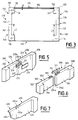
- Figure 1 shows a storage unit which has an upper shelf 10 and a lower shelf 12 substantially rectangular. We will consider in the following that these tablets are arranged horizontally.
- the furniture also includes means forming uprights which, when the furniture is assembled, cooperate with the upper and lower shelves to hold them one above the other. More precisely, as can be seen in the horizontal section in FIG. 2, the upright means comprise four vertical elements 14, 16, 18 and 20 which, in the example shown, are arranged at the four corners of the shelves 10 and 12.
- FIGS. 1 and 2 When the piece of furniture is assembled as shown in FIGS. 1 and 2, it comprises a front face 22, a rear face 24, and two lateral faces 26 and 28.
- the piece of furniture furthermore comprises wall means which close at least one of its faces, called “closed face”, when the piece of furniture is assembled.
- the front face 22 of the cabinet is open, while its rear face 24 and its two lateral faces 26 and 28 are closed.
- the means forming uprights comprise a first and a second support element, respectively arranged at each of the two ends of the closed face considered when the piece of furniture is assembled.
- the elements 18 and 20 previously mentioned respectively constitute the first and the second support elements associated with the closed rear face 24 and are located at the two lateral ends of this face.
- the elements 14 and 20 on the one hand, and the elements 16 and 18 on the other hand constitute respectively the first and second support elements for the closed faces 26 and 28 and are located at the front and rear ends of these faces.
- the sides 42 and 46 have a height substantially equal to the height H of the support elements, that is to say the height which separates the upper face of the lower shelf 12 and the lower face of the upper shelf 10 from the cabinet.
- the height of the sides may be less than that of the support elements.
- the mixed parts 40 and 44 are arranged so that the respective free ends 42a and 46a of their sides 42 and 46 are adjacent to each other, so that the rear face 24 of the cabinet is completely closed by the support elements 18 and 20 and by the two sides 42 and 46.
- the mixed parts 40 and 44 are identical and the length L2 of their sides 42 and 46 is equal to half the length which separates the two support elements 18 and 20.
- the sidewall forms a single part with the support element. It is therefore sometimes difficult to distinguish the two parts of the mixed part. In the example of Figure 2, this distinction is possible due to the difference in thickness between the sidewall and the support element. If this is not the case, it will be considered that the condition that the length of the sidewall is at most equal to the distance between the two support elements results in the fact that the total length of the mixed part is such that the free end of this mixed part reaches at most at the level of the second support element when the piece of furniture is assembled.
- the sides 42 and 46 of the mixed parts 40 and 44 form the wall means of the same closed face 24, while the sides 32 and 36 of the mixed parts 30 and 34 respectively form the wall means of the side faces 26 and 28 of the furniture.
- the closed face 26 is, for its part, equipped with a mixed part 30, a first part of which constitutes the first support element 14 of this face 26 and of which a second part is integral with the first and constitutes a flank 32 substantially plane which extends from one side of the first support element 14.
- the flank 32 of the composite part 30 has a height substantially equal to the height H of the support elements, that is to say the height which separates the upper face of the lower shelf 12 and the lower face of the upper shelf 10 from the cabinet.
- the height of the sidewall may be less than that of the support elements.
- the sidewall 32 When the piece of furniture is assembled, the sidewall 32 extends parallel to the edge of the upper and lower shelves which define the closed face 26. Its length L1, in this direction, is substantially equal to the distance between the first and second support elements 14 and 20. Thus, the closed face 26 is completely closed by the outer sides of the support elements 14 and 20 and by the outer face of the sidewall 32.
- the mixed part 30 is a single piece, the sidewall 32 forming a single piece with the first support element 14. It should be noted that the flank 32 could also be provided with a length less than the distance which separates the elements 14 and 20 in order to only partially close the face.
- a mixed part 34 identical to the mixed part 30 is associated with the closed face 28, the side 36 of this mixed part forming a wall for this closed face.
- the mixed parts are associated with other wall means.
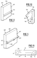
- the front face 122 of the cabinet is open, while its rear face 124 and its lateral faces 126 and 128 are closed.
- the lateral faces 126 and 128 are closed in a similar manner to the rear face 24 of the cabinet of FIG. 2, that is to say that two mixed parts, respectively 130, 134 and 140, 144, are associated with each of these faces.
- the lengths L3 of the sides 132 and 136 of the mixed parts 130 and 134 are equal to each other and are substantially equal to the length which separates the support elements 114 and 120 respectively arranged at the front and rear ends of the lateral face 126.
- the faces 126 and 128 having the same length, the sides 142 and 146 of the mixed parts 140 and 144 also have the length L3.
- each of the two support elements 118 and 120 which are located at the two ends of the rear face 124 has a vertical groove respectively 119 and 121.
- the grooves are directed towards each other when the two mixed parts 134 and 144 are in place, and the two ends 151 and 152 of the wall element 150 can be inserted in these grooves 119 and 121.
- an offset "d" remains between the rear edges of the shelves 10 and 12 and the rear face of the wall element 150.
- this shift does not inevitably harm the aesthetics.
- the invention therefore makes it possible to combine conventional wall elements, for example of the type sold under the brand Isorel, such as element 150, and mixed parts in accordance with the invention.
- the mixed parts 130, 134, 140 and 144 are practically identical, apart from the grooves 119 and 121.
- Figure 4 is a vertical sectional figure which illustrates the attachment between the first parts of the mixed parts and the upper or lower shelves.
- the upper end of the first part 16 of the composite part 34 is fixed to the upper shelf 10.
- the latter is pierced with a hole 50 in which is inserted an extension cylindrical 17 of the support element 16, extending beyond the upper end 16a of the latter.
- the cylindrical extension 17 is threaded and has a diameter less than the diameter of the hole 50.
- the assembly is held in place by means of a cap 52 comprising a plate 54 from which extends a hollow cylindrical sleeve 56.
- the external diameter of the cylindrical sleeve 56 is substantially equal to the diameter of the hole 50, and the internal cylindrical face of the sleeve 56 is tapped, so that the part 52 and the extension 17 cooperate by screwing.
- the plate 54 may have an angular external shape, for example square, so that this plate constitutes a grip facilitating screwing without making the use of a particular tool compulsory.
- All the support elements can be provided with such cylindrical extensions at each of their two ends.
- one end of the support elements may be provided with a threaded extension similar to the extension 17, while the other end would be provided with a hollow cylindrical sleeve similar to the sleeve 56 of the cap 52.
- the user could choose not to superimpose the furniture by having a cap provided with a cylindrical male sleeve capable of cooperating by screwing with the hollow cylindrical sleeve, or to superimpose two pieces of furniture by screwing the male cylindrical extension of a support element in the hollow cylindrical sleeve (female) threaded with another support element.
- the mixed parts in accordance with the invention are compatible with such a very simple method of attachment. These mixed parts can be produced by blowing or by plastic molding and be directly fitted with male or female fixing sleeves at the ends of their respective first parts.
- the thickness E1 of the side of each mixed part is substantially equal to half the thickness E2 of the first part of the part mixed, i.e. the support element. These thicknesses are obviously measured perpendicular to the plane defined by the axis of the first support element and by the direction (perpendicular to this axis) in which the side of the mixed part extends from the first part of this mixed part.
- This arrangement allows, as seen in Figure 11, to have two mixed parts so as to achieve a particularly compact packaging of the furniture for marketing.
- This figure indeed shows the mixed parts 40 and 44 arranged for their packaging.
- the internal faces of their sides 42 and 46 are located one against the other, and the end 42a of the side 42 is disposed against the internal face of the first part 18 of the composite part 44, while the free end 46a flank 46 east disposed against the internal face of the first part 20 of the mixed part 40.
- the two parts 40 and 44 thus arranged form an assembly whose thickness is equal to the thickness E2 and whose length is equal to the length of a flank increased by twice the length of a support element.
- the piece of furniture advantageously comprises means for aligning the sides of two mixed pieces forming the wall means of a closed face of the piece of furniture when this piece of furniture is assembled.
- Three variants of such means are illustrated in FIGS. 5 to 7. It should be noted that the mixed parts are shown very schematically, so that the sleeves for fixing to the upper or lower shelves have not been shown, from which they may be provided.
- the means for aligning the sides of the two mixed parts include an alignment member able to cooperate with the sides of these mixed parts in the vicinity of their adjacent free ends.
- the mixed parts 200 and 206 each have a first part constituted by a support element, respectively 202 and 208, and a second part which constitutes the side, respectively 204 and 206. These two mixed parts are arranged so that the free ends 204a and 210a of the two sides are adjacent and aligned. Thus, each of the two sides 204 and 210 has a notch, respectively 205 and 211, open on its free end.
- the two mixed parts 200 and 206 are arranged so that their free ends are adjacent, the two notches 205 and 211 are in continuity with one another and form a recess 212.
- the alignment part 214 has dimensions adapted to those of this recess. To keep the sides of the two mixed parts aligned, it suffices to place the alignment part 214 in the recess 212.
- the notches 205 and 211 are produced on the internal faces of the two sides.
- the recess extends only on the vertical internal face.
- attachment means such as projecting studs and cavities of complementary shape can be provided, respectively in the bottom of the recess and on the face of the piece 214 intended to cooperate with this bottom.
- it is the bottom of the recess 214 which has cavities 216, while the alignment piece 214 is provided with studs of complementary shape (not shown).
- studs of complementary shape not shown.
- FIG. 6 the elements similar to those of FIG. 5 are designated by the same references, increased by 100.
- the sides 304 and 310 each have a notch, respectively 305 and 311, open on their respective free ends 304a and 310a. This time, the notches are made from the upper edge, respectively 303 and 309 of the flank considered. To keep the sides 304 and 310 aligned when their free ends are adjacent, it suffices to introduce the alignment bar 314 into the continuous recess formed by the alignment of the notches 305 and 311. This recess being only open upwards, it is not possible to provide means for hooking the bar in the notches.
- wedging bar 314 of FIG. 6 can be directly secured to the underside of the upper shelf 10 of the cabinet, and produced in one piece with the latter. In fact, the wedging piece can be independent or integral with one of the shelves of the cabinet.
- FIGS. 5 and 6 the upper ends of the mixed parts are only shown diagrammatically, but it should be understood that similar alignment means can be provided in the vicinity of the lower ends of these parts. It should also be noted that one could choose to make flanks free of notches, and to provide on the underside of the upper shelf and / or on the upper face of the lower shelf, a protruding bar forming a stop to ensure the correct position of the sides of the mixed parts.
- Figure 7 shows another variant of means for aligning the sides of the two mixed parts.
- the side 404 of the mixed part 400 of same as the side 410 of the mixed part 406, has, at its free end, a recess which extends over the entire height of this side and leaves a strip, respectively 404a and 410a, whose thickness is substantially equal to half the thickness of the sidewall.
- the strip of one of the flanks constitutes the wall of a recess into which the strip of the other flank is inserted to wedge the flanks of the two mixed parts in alignment position when they form the wall d 'one side of the cabinet.
- FIGS. 8 and 9 show in partial perspective a mixed part constituting at least part of the wall means of one of the closed faces of the piece of furniture, the side of the piece of furniture opposite this closed side being also closed using the side of a similar mixed piece
- the sides of the two mixed parts closing two opposite walls of the cabinet are provided, on their respective internal faces (that is to say on the faces which are turned towards one another) with means forming slides horizontal.
- the internal face 507 of the sidewall 504 has a horizontal rib 520 whose upper face 521 is planar.
- This horizontal rib is integral with the mixed part, that is to say it is made in one piece with it. Thanks to this configuration, when two similar mixed parts equip the two opposite walls of the cabinet, the horizontal ribs 520 are located at the same height, so that their respective upper faces can serve as a sliding support at the edge of a drawer.
- the internal face 607 of the side 604 of the mixed part 600 is provided with orifices allowing the attachment of a separate slide 620.
- This slide can be fitted with hooks 622 directed upwards and portions of support 624 having, on their faces intended to cooperate with the internal face 607, an engagement pin 625.
- the side wall 604 has orifices, opening onto its face internal 607 and respectively adapted to receive the hook 622 and the pin 625.
- the side 704 of the mixed part 700 comprises at least one projection 730 which is integral with this mixed part and is located on the internal face 707 of the latter.
- the projection 730 can be one of the support elements for an intermediate shelf.
- the mixed parts 130, 134, 140 and 144 of FIG. 3 could each be fitted with a projection of this type.
- the four projections located at the same height would constitute four support points for an intermediate shelf. It is obviously possible to have several projections vertically so as to install several intermediate shelves. Similarly, it would be possible to equip the internal faces of the sides 30 and 34 with several projections of this type to support one or more intermediate shelves.
- the projection 730 is arranged in the junction area of the sidewall 704 and the support element 702 of the composite part 700.
Landscapes
- Life Sciences & Earth Sciences (AREA)
- Engineering & Computer Science (AREA)
- Wood Science & Technology (AREA)
- Assembled Shelves (AREA)
Applications Claiming Priority (2)
| Application Number | Priority Date | Filing Date | Title |
|---|---|---|---|
| FR9513229 | 1995-11-08 | ||
| FR9513229A FR2740667B1 (fr) | 1995-11-08 | 1995-11-08 | Meuble de rangement |
Publications (1)
| Publication Number | Publication Date |
|---|---|
| EP0772985A1 true EP0772985A1 (de) | 1997-05-14 |
Family
ID=9484366
Family Applications (1)
| Application Number | Title | Priority Date | Filing Date |
|---|---|---|---|
| EP96402341A Withdrawn EP0772985A1 (de) | 1995-11-08 | 1996-11-05 | Aufraümmöbel |
Country Status (3)
| Country | Link |
|---|---|
| US (1) | US5931552A (de) |
| EP (1) | EP0772985A1 (de) |
| FR (1) | FR2740667B1 (de) |
Families Citing this family (2)
| Publication number | Priority date | Publication date | Assignee | Title |
|---|---|---|---|---|
| PL198090B1 (pl) * | 2002-03-18 | 2008-05-30 | Black Red White Sa | Zespół mebli modułowych |
| SE545331C2 (en) * | 2021-02-24 | 2023-07-04 | Ikea Supply Ag | Storage furniture assembly comprising a divider panel allowing for positioning the storage furniture in two different orientations |
Citations (6)
| Publication number | Priority date | Publication date | Assignee | Title |
|---|---|---|---|---|
| US2072383A (en) * | 1934-02-06 | 1937-03-02 | Rottman George | Knock down cabinet |
| US3493281A (en) | 1968-03-12 | 1970-02-03 | Sylvania Electric Prod | Assemblable furniture |
| FR2163787A5 (de) * | 1971-12-01 | 1973-07-27 | Mangiarotti Angelo | |
| FR2370452A1 (fr) * | 1976-11-15 | 1978-06-09 | Lundqvist Harald | Ensemble de rayonnage |
| FR2407689A1 (fr) * | 1977-11-04 | 1979-06-01 | Kump Ernest | Perfectionnements aux recipients, notamment pour le rangement de documents |
| US5368380A (en) * | 1993-01-08 | 1994-11-29 | Rubbermaid Incorporated | Cabinet assembly |
Family Cites Families (14)
| Publication number | Priority date | Publication date | Assignee | Title |
|---|---|---|---|---|
| FR1122957A (fr) * | 1955-04-18 | 1956-09-14 | Bibliothèques et meubles démontables et extensibles | |
| FR1357057A (fr) * | 1963-02-20 | 1964-04-03 | Perfectionnements aux meubles constitués d'éléments juxtaposables et superposables | |
| CH495729A (de) * | 1969-07-16 | 1970-09-15 | Daehler Hermann | Element-Aufbaumöbel |
| JPS5228666Y2 (de) * | 1971-06-23 | 1977-06-30 | ||
| CA971704A (en) * | 1972-08-10 | 1975-07-29 | John Peng | Convertible modular furniture-luggage units |
| GB1489875A (en) * | 1975-01-14 | 1977-10-26 | Courtney Pope Ltd | Knock-down display units |
| AT348705B (de) * | 1975-08-05 | 1979-02-26 | Herig Willi | Bauelementensatz zum herstellen von schrankwaenden od. dgl. |
| FR2334324A1 (fr) * | 1975-12-11 | 1977-07-08 | Hoarau Jean | Etagere demontable |
| DE2620402A1 (de) * | 1976-05-08 | 1977-11-24 | Peha K & K Moebel Gmbh | Zerlegbares kastenmoebel bzw. regal |
| FR2422363A1 (fr) * | 1978-04-10 | 1979-11-09 | Chazal Ets R | Meubles demontables et leur dispositif d'assemblage |
| US5221131A (en) * | 1990-06-04 | 1993-06-22 | Patz Sales Corp. | Shelving assembly |
| US5048902A (en) * | 1990-10-15 | 1991-09-17 | Triad Technologies, Inc. | Deck storage cabinet |
| US5240317A (en) * | 1992-01-07 | 1993-08-31 | Presnick Michael C | Knock-down skeletal cabinet |
| US5642923A (en) * | 1995-10-20 | 1997-07-01 | Temp Top Container Systems, Inc. | Removable shelf system for a transport container |
-
1995
- 1995-11-08 FR FR9513229A patent/FR2740667B1/fr not_active Expired - Fee Related
-
1996
- 1996-11-05 EP EP96402341A patent/EP0772985A1/de not_active Withdrawn
- 1996-11-06 US US08/744,778 patent/US5931552A/en not_active Expired - Fee Related
Patent Citations (6)
| Publication number | Priority date | Publication date | Assignee | Title |
|---|---|---|---|---|
| US2072383A (en) * | 1934-02-06 | 1937-03-02 | Rottman George | Knock down cabinet |
| US3493281A (en) | 1968-03-12 | 1970-02-03 | Sylvania Electric Prod | Assemblable furniture |
| FR2163787A5 (de) * | 1971-12-01 | 1973-07-27 | Mangiarotti Angelo | |
| FR2370452A1 (fr) * | 1976-11-15 | 1978-06-09 | Lundqvist Harald | Ensemble de rayonnage |
| FR2407689A1 (fr) * | 1977-11-04 | 1979-06-01 | Kump Ernest | Perfectionnements aux recipients, notamment pour le rangement de documents |
| US5368380A (en) * | 1993-01-08 | 1994-11-29 | Rubbermaid Incorporated | Cabinet assembly |
Also Published As
| Publication number | Publication date |
|---|---|
| FR2740667A1 (fr) | 1997-05-09 |
| FR2740667B1 (fr) | 1998-01-23 |
| US5931552A (en) | 1999-08-03 |
Similar Documents
| Publication | Publication Date | Title |
|---|---|---|
| EP2641505B1 (de) | Möbelstückkorpus | |
| EP0106734A1 (de) | Gerüstbildende Vorrichtung für ein Möbelstück zum Einräumen, beispielsweise ein Regal | |
| WO1995008973A1 (fr) | Cercueil pliable | |
| EP2143846B1 (de) | Unterputzdose für Sanitärinstallationen | |
| FR2956590A1 (fr) | Jeu de construction | |
| EP1264052A1 (de) | Baustein mit verriegelung | |
| CA3032086A1 (fr) | Caisson de meuble | |
| EP0772985A1 (de) | Aufraümmöbel | |
| WO2014096577A1 (fr) | Caisson de meuble | |
| EP0665167A1 (de) | Schachtel mit Aussenwänden und Innenträgerkörper | |
| EP1900303A1 (de) | Blatt für Baumaterial | |
| EP0914790B1 (de) | Eckverbindungselement und Sammelbriefkastenanlage mit mindestens einem solchen Element | |
| FR2675672A1 (fr) | Tiroir en tole. | |
| FR2665062A1 (fr) | Caisson de rangement a tiroirs, pour bureaux. | |
| FR2693984A1 (fr) | Bac de rangement démontable. | |
| FR2978337A1 (fr) | Presentoir | |
| FR2573824A3 (fr) | Dispositif de realisation de meubles a assemblage par l'utilisateur. | |
| EP0867373A1 (de) | Verpackungsschale | |
| FR2677084A1 (fr) | Dispositif d'assemblage pour profiles creux. | |
| FR2781616A1 (fr) | Boite d'encastrement susceptible d'etre jumelee avec une autre, notamment pour appareillage electrique | |
| FR3057746A1 (fr) | Baguette d'assemblage d'un caisson de meuble. | |
| FR2639523A1 (fr) | Meuble a ossature metallique | |
| FR2761122A1 (fr) | Structure modulaire realisee a partir d'elements assembles par des tiges traversantes, et outil de realisation associe | |
| FR2764532A1 (fr) | Procede de realisation d'une bordure comportant un coin sur une piece en tole ; piece moulee pour la mise en oeuvre du procede ; combinaison d'une piece en tole pliee et d'une piece moulee, obtenue par la mise en oeuvre du procede | |
| FR2777733A1 (fr) | Armoire electrique dont les montants du cadre sont realises par repliage de ses parois en formant un logement interieur |
Legal Events
| Date | Code | Title | Description |
|---|---|---|---|
| PUAI | Public reference made under article 153(3) epc to a published international application that has entered the european phase |
Free format text: ORIGINAL CODE: 0009012 |
|
| AK | Designated contracting states |
Kind code of ref document: A1 Designated state(s): AT BE CH DE DK ES FR GB IT LI NL |
|
| 17P | Request for examination filed |
Effective date: 19971006 |
|
| GRAG | Despatch of communication of intention to grant |
Free format text: ORIGINAL CODE: EPIDOS AGRA |
|
| 17Q | First examination report despatched |
Effective date: 19990311 |
|
| GRAG | Despatch of communication of intention to grant |
Free format text: ORIGINAL CODE: EPIDOS AGRA |
|
| STAA | Information on the status of an ep patent application or granted ep patent |
Free format text: STATUS: THE APPLICATION IS DEEMED TO BE WITHDRAWN |
|
| 18D | Application deemed to be withdrawn |
Effective date: 20000531 |